1
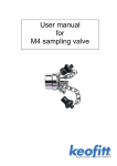
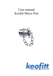
MICRO PORT - MULTI MICRO PORT 49 User Manual D O N ’ T G A M B L E W I T H Y O U R S A M P L E ™ DOCUMENT VERSION LOG The table below lists previous versions of this User Manual and states the major changes between versions. This version list is introduced in October 2015. Version # Version date 1 5th October 2015 Major changes from previous versions Complete revision and new layout. INTRODUCTION: MANUFACTURER: TYPE: YEAR OF INTRODUCTION: YEAR OF REVISED DESIGN: MANUAL LAST UPDATED: Keofitt A/S Kullinggade 31 5700 Svendborg, Denmark Micro Port & Multi Micro Port 49 1982/2004 -/2014 Oct 2015 The English version of this Manual is the governing version and it is the only authorized version. Consequently, KEOFITT cannot be held liable for other versions including translations of this Manual. CONTENTS 1. PRESENTATION.............................................................................................................................. 7 1.1. Micro Port..........................................................................................................................................7 1.2. Multi Micro Port 49...........................................................................................................................7 2. MICRO PORT FUNCTION................................................................................................................. 8 2.1. Micro Port..........................................................................................................................................8 2.2. Multi Micro Port 49...........................................................................................................................8 3. EVERYDAY USE OF THE MICRO PORTS........................................................................................10 3.1. Sampling using the Micro Port...................................................................................................... 10 3.2. Sampling using the Multi Micro Port 49....................................................................................... 11 4. TECHNICAL DATA..........................................................................................................................12 5. MICRO PORT MODELS..................................................................................................................13 6. PARTS AND ACCESSORIES..........................................................................................................14 7. MOUNTING INSTRUCTIONS...........................................................................................................15 7.1. Location........................................................................................................................................... 15 7.2. Before welding................................................................................................................................ 15 7.3. After welding................................................................................................................................... 15 8. WELDING INSTRUCTIONS.............................................................................................................16 8.1. Tank welding................................................................................................................................... 16 8.2. Pipe welding................................................................................................................................... 16 9. BLOCK DIAGRAMS........................................................................................................................ 17 9.1. Micro Port type P, pipe (900057 or 900014)............................................................................... 17 9.2 Micro Port, type T, tank (900056 and 840001)........................................................................... 17 10. MAINTENANCE............................................................................................................................18 10.1. Replacing septum on Micro Port................................................................................................. 18 10.2. Replacing the wick....................................................................................................................... 18 10.3. Replacing the testimonial foil and septa.................................................................................... 18 10.4. Replacing o-rings......................................................................................................................... 19 11. DATASHEETS...............................................................................................................................20 11.1 Butyl membrane - art. no. 900049............................................................................................. 20 1. PRESENTATION The Keofitt Micro Port and the Keofitt Multi Micro Port 49 provide an easy and hygienic solution for extracting liquid samples from a production batch. This is obtained through a thick membrane and an overall design with the purpose of eliminating all dead spaces and crevasses, where bacteria could grow. Throughout this manual “Micro Ports” designates both the single-septum “Micro Port” and the multiseptum “Multi Micro Port 49”. The Micro Ports are designed for taking samples of low viscosity products through a septum using a hypodermic needle or a syringe with a minimum risk of contamination. The Micro Port comes in 2 sizes, each in a number of variants as described in the following. 1.1. Micro Port The single-septum model comes in the following 3 versions: ITEM # DESIGNATION DESCRIPTION 900056 900057 900014 Tank Pipe welding 1” Pipe welding NW25 To be welded on to a tank To be welded on to a 1” pipe To be welded on to a 25 mm pipe 1.2. Multi Micro Port 49 This model contains 7 individual septa, allowing for many more samples to be taken from a given batch. This multi-septum model comes in the following versions: ITEM # DESIGNATION DESCRIPTION 840001 840009 840020 Tank Welding Varivent Ø68 Clamp 3” To be welded on to a tank Fits a 68 mm Varivent housing Fits a 3” Tri-Clamp ferule KEOFITT USER MANUAL PAGE 7 2. MICRO PORT FUNCTION The Micro Ports are designed to regularly take representative samples in the production process by piercing a needle through a septum made from synthetic rubber. The septum is the only barrier between the process side and the environment. Since each piercing, each sample taken, will cut into the septum, there is a limit to the number of samples that can be withdrawn through the same septum and still maintain the septum’s tightness. An important factor here is to avoid piercing the same place on the septum twice. To this end the Multi Micro Port is foreseen with a sheet steel matrix placed in front of the septum having 7 predefined piercing positions for each septum. This allows for 7x7=49 samples taken, all at different places on the septum. 2.1. Micro Port The Micro Port contains one septum held in a housing (the base) and kept in place by a hex nut. A pin screw axially positioned off-centre in the hex nut flange acts as a locking device once the hex nut is tightened to the right position. The housing and the hex nut both have a centre hole through which you pierce the hypodermic needle or the syringe. The hole in the hex nut is closed by means of a plug, which is temporarily removed during sampling. The plug is foreseen with an o-ring for a tight fit. In the cavity between the plug and the septum you may place a wick soaked in alcohol or any other appropriate disinfectant to act as an additional barrier to the ambient. 2.2. Multi Micro Port 49 The Multi Micro Port 49 features 7 septa held in a housing and kept in place by an inner steel plate, which in turn is secured by a ring shaped nut. The inner steel plate is foreseen with 7 small holes in front of each septum and as such predefining a total of 49 individual sample points. A replaceable selfadhesive plastic foil on the inner plate indicates which holes have not been used for taking samples. When piercing the needle the foil surface is broken, which is clearly visible afterwards. In this way one efficiently avoids piercing the same place KEOFITT USER MANUAL PAGE 8 twice, thus virtually eliminating the risk of leakage. Between sampling the septum area is covered by a steel cap, featuring an o-ring for a tight fit against the inside surface of the threaded ring. KEOFITT USER MANUAL PAGE 9 3. EVERYDAY USE OF THE MICRO PORTS This chapter gives an introduction to how to take samples using the Micro Port and the Multi Micro Port 49 respectively. When using a syringe or a needle other than the Keofitt Hypodermic needle, pay attention to the shape and sharpness of the tip and the thickness of the needle. Blunt tips or an inappropriate shape of the tip may cause the septum to leak prematurely. The risk of leakages will increase rapidly with needles thicker than 1.25 mm. Avoid piercing the septum twice or even several times in the same position, as it will inevitably lead to leakages, surely depending on the thickness of the needle and the pressure on the process side. IMPORTANT: • All specifications regarding sampling through Micro Ports assume the use of Keofitt Hypodermic needles and Keofitt septum 3.1. Sampling using the Micro Port To take a sample perform the following steps: 1. Remove the plug 2. Remove (unscrew) the cotton wick (if present) and discard it 3. Clean and disinfect the septum using a new wick soaked in an appropriate disinfectant 4. Discard the wick 5. Immediately after cleaning/disinfecting pierce the septum with a hypodermic needle or a syringe holding it at a slight angle relative to the axes of the Micro Port; avoid piercing the same place twice 6. Extract the required sample volume 7. Pull out the hypodermic needle or syringe 8. If an additional hygiene barrier is required, place (screw in) a new wick in the plug soaked in alcohol or another appropriate disinfectant 9. Put the plug back in place after having greased the o-ring with an appropriate lubricant for easy removal next time IMPORTANT: • In order to avoid penetrating the septum twice at the same place tilt the needle slightly (5-10 degrees) relative to the Micro Port axis and use a different orientation in space from sample to sample. • If the septum starts leaking, an intermediate solution is a) to loosen the pin screw, b) tighten the hex nut up to a quarter of a turn and c) retighten the hex nut. Replace septum at next possible occasion. WARNING: • Be careful not to prick yourself with the needle. Note, that the Keofitt hypodermic needle has a sharp point at both ends. • The larger the number of taken samples with each septum, the higher the danger of cross contamination and the lower the septum’s ability to withstand pressure. KEOFITT USER MANUAL PAGE 10 3.2. Sampling using the Multi Micro Port 49 The Multi Micro Port 49 is foreseen with 7 septa and a matrix of perforations (small holes guiding the needle) that determines 49 individual sampling points. To take a sample perform the following steps: 1. Remove the cap 2. Locate a sampling position not previously used, i.e. an intact plastic foil over a perforation 3. Using a swab or similar clean and disinfect the area where you want to take the sample 4. Clean and disinfect the hypodermic needle or the syringe 5. Immediately after cleaning/disinfecting pierce the septum with the hypodermic needle or a syringe 6. Extract the required sample volume 7. Pull out the hypodermic needle or syringe 8. Put the cap back in place after having greased the o-ring with an appropriate lubricant for easy removal next time The order in which the 49 positions are used is of no importance. However it is advisable to start out at a 12 o’clock position and then move clockwise, finishing one septum before moving on to the next. In this way it is easier to locate a new unused sampling point. Due to the 49 individual sampling points being used only once, it is very unlikely that a septum leaks. Should it happen, tightening the threaded ring by hand would be an intermediate solution. Irrespective of the required number of samples per batch, it is recommended to replace all 7 septum and the testimonial foil before starting a new batch. Decision to leave both used and unused septum untouched for use during the next and possibly even later batches must be taken by the customer based on the customer’s information on actual production parameters, such as temperature, pressure, chemical composition of product, time in operation etc. WARNING: • Be careful not to prick yourself with the needle. Note, that the Keofitt hypodermic needle has a sharp point at both ends. KEOFITT USER MANUAL PAGE 11 4. TECHNICAL DATA The following data apply to both Micro Port and Multi Micro Port 49, unless otherwise specified. 4.1. Material (product contact) Steel parts: AISI 316L (1.4404) Septum: Butyl IIR (Isobutylene Isoprene Rubber) (B402F - grey) 4.2. Material (without product contact) Steel parts: AISI 316L (1.4404) O-ring: EPDM (FDA · EU 1935/2004) 4.3. Surface finish Outside: Electro polished Ra <= 1.2 μm Inside & Process: Ra<=0.5μm 4.4. Pressure and temperature Pressure: 0-6 bar(g) / 0-87 psi(g) Temperature: 1-110°C / 34-230°F 4.5. Certification Steel parts: 3.1 Steel parts: Ra certificate Septum: EU 1935/2004 · FDA §177.2600 · USP 4.6. Viscosity Viscosity range:0-50 cP (with only microscopic particles) 4.7. Weight Micro Port: 0.16 kg / 0.35 lbs Multi Micro Port 49: 0.86 kg / 1.80 lbs KEOFITT USER MANUAL PAGE 12 KEOFITT USER MANUAL PAGE 13 For further product information – material, dimensions etc. – please refer to the specific datasheet at www.keofitt.dk. MICRO PORT / MULTI MICRO PORT 49 PTFE membrane 840020 840009 7xEPDM membrane 7xEPDM membrane 7xEPDM membrane 840001 Clamp 3” 900014 le Varivent Ø68 900057 le le ab le Multi Micro Port 49 900056 ab ab ta vai l ab le Tank Welding ta vai l le No ava il No t No ava il ab le Pipe Welding NW25 t ab ab No ta vai l ab Micro Port t ava il No ava il No ab No ta vai l Pipe Welding 1” le ab No Silicone membrane le ab t Butyl (IRR) membrane le ta vai l No No le ta vai l No ab Tank No ta vai l le ta vai l 5. MICRO PORT MODELS For further product information – material, dimensions etc. – please refer to the specific datasheet at www.keofitt.dk. 900049 BUTYL MP 900049 BUTYL MP MICRO PORT PARTS & ACCESSORIES 840055 FILM MULTI MP 840055 FILM MULTI MP 400208 O-RING 68 FDA 400208 O-RING 68 FDA Septum Misc. O-Rings Septum KEOFITT USER MANUAL Misc. O-Rings MICRO PORT PARTS & ACCESSORIES 840118 TOOL MULTI MP 900822 9.3X2.4 EPDM 840118 TOOL MULTI MP 900822 9.3X2.4 EPDM 900054 NEEDLE MP 900824 14X4 EPDM 900054 NEEDLE MP 900824 14X4 EPDM KEOFITT KEOFITT MICRO PORT MICRO - PARTS PORT & - PARTS ACCESSORIES & ACCESSORIES 900055 WICK MP 900825 44.6X2.4 EPDM 900055 WICK MP 900825 44.6X2.4 EPDM 900077 CHAIN MP 900077 CHAIN MP 900441 PLUG MICRO PORT 900441 PLUG MICRO PORT 6. PARTS AND ACCESSORIES PAGE 14 7. MOUNTING INSTRUCTIONS 7.1. Location It does not matter whether the Micro Ports are installed vertically or horizontally. Note the following when determining the position of the Micro Ports: • Secure good flow of product in front of the septum • Avoid dead space at the product side of the septum • As sampling is a manual operation secure sufficient room for the operator around the Micro Port. 7.2. Before welding The Micro Port base (housing) is the item to be welded. The cap/plug, the septum and all other components must be removed from the base before welding, as heat from the welding process will otherwise damage them. 7.3. After welding The base is welded to the tank or pipe following the instructions in chapter 8. Once the base has cooled off the other components must be fitted to the base, as follows: For the Micro Port: 1. Fit the o-ring in the base 2. Put new septum in place and press firmly using clean gloves or other sanitary measures to avoid finger prints 3. Take sanitary precautions, for example run disinfectant soaked cotton wick over the septum 4. Make sure the pin screw is in place in the hex nut and protruding 1-2 mm above the hex nut’s outer surface 5. Tighten the hex nut completely until the mechanical stop inside the base 6. Unscrew the Hex nut 1/4 to 1/3 of a turn 7. Turn the pin screw until it hits the base and tighten it to secure the nut from unscrewing itself For the Multi Micro Port 49: 1. Put 7 new septum in place and press firmly using clean gloves or other sanitary measures to avoid finger prints 2. Take sanitary precautions, for example run disinfectant soaked cotton wick over the septum 3. Replace the inner plate in a way where the protruding pin on the backside of the inner plate enters into the corresponding hole in the base 4. Place the nut (threaded ring) in the base and turn clockwise until firm contact with the inner plate 5. Tighten the nut by hand a further 1/8 to ¼ turn to assure tightness from compression of the septum 6. Replace the cap in the nut after having greased the o-ring with an appropriate lubricant KEOFITT USER MANUAL PAGE 15 8. WELDING INSTRUCTIONS Please consult Chapter 9 BLOCK DIAGRAMS for corresponding illustrations on welding to pipe or tank. 8.1. Tank welding For type T (tank) it is necessary to drill a hole into the tank wall. Then fit the Micro Port base into this hole, flush with the inside of the tank. Welding should be carried out as a penetration welding. Hole diameter for Micro Port: ø28 mm Hole diameter for Multi Micro Port 49: ø84 mm Tank wall thickness less than 4 mm: Weld from inside. Tank wall thickness greater than 4 mm: Weld from both in- and outside. Since type T has a solid bottom end, penetration welding will not damage the housing. However, the use of purge gas in either the form of Argon or Formier gas is recommended in order to give the best result. After the complete welding process the internal weld (inside the tank) must be polished to the required surface roughness. IMPORTANT: • When grinding/polishing the internal weld, make sure the Micro Port seat area(s) are not touched/damaged. 8.2. Pipe welding For type P (pipe) penetration welding must be carried out from the outside. Micro Port is machined with a recesslike shoulder on the outside of the tank end, which gives approximately the same material thickness (1.5mm material thickness) as in the pipe wall. This machined shoulder can be modified according to the customer’s wishes. For optimal welding result follow the method listed here: • A collar is made on the pipe section in order the Micro Port to meet a flat contact face. This flaring must look like a T-piece, as shown in the example below. • The pipe section and the base are sealed off with a sponge, rubber or similar. • Purge gas such as Argon or Formier gas is fed through the base into the pipe section and the system is now filled with 6 times the estimated volume of the pipe section. All O2 is thus expelled from the system and welding can commence. • Welding can take place with the purge gas continually flowing in the system. • The gas must remain in the system until the item is hand warm, after which the setup can be dismantled. Recommended welding current is as follows: • Micro Port welded onto a 2 mm 3” stainless steel: 40-50 Amp. • Micro Port welded onto a 1.25 mm 2” stainless steel: approx. 30 Amp. NOTE: • Keofitt may upon request supply all P type Micro Port welded onto a pipe section according to customer specifications. Flaring is thus avoided and only an orbital (girth) weld is required. KEOFITT USER MANUAL PAGE 16 9. BLOCK DIAGRAMS 9.1. Micro Port type P, pipe (900057 or 900014) Welded to pipe 9.2 Micro Port, type T, tank (900056 and 840001) The drawing shows the Micro Port, but the welding principles also apply to the Multi Micro Port 49. Welded to tank outside Welded to tank inside KEOFITT USER MANUAL PAGE 17 10. MAINTENANCE The regular maintenance consists of the following: • Replacing septum (only Micro Port) • Replacing wick (only Micro Port) • Replacing the testimonial foil and septum (only Multi Micro Port) Occasional maintenance consists of replacing worn or damaged o-rings. 10.1. Replacing septum on Micro Port Order of operation to replace septum is as follows: 1. Make sure the process tank or the piping behind the Micro Port is empty and not under pressure 2. Remove plug and cotton wick. 3. Loosen the pin screw 4. Turn Hex nut counter clockwise to unscrew from the base. 5. Pull out old septum. 6. Put new septum in place and press firmly using clean gloves or other sanitary measures to avoid finger prints 7. Take sanitary precautions, for example run disinfectant soaked cotton wick over the septum. 8. Make sure the pin screw is in place in the hex nut and protruding 1-2 mm above the hex nut’s outer surface 9. Tighten the hex nut completely until the mechanical stop 10. Unscrew the Hex nut 1/4 to 1/3 of a turn 11. Turn the pin screw until it hits the base and tighten it to secure the nut from unscrewing itself 12. Put new disinfectant soaked cotton wick in the plug (if required) 13. Replace the plug in the hex nut after having greased the o-ring with an appropriate lubricant. WARNING: • Never unscrew the Micro Port while the production line is in operation or under pressure • Tightening the Hex nut too much will make piercing the septum difficult, as the septum becomes compressed and hard. 10.2. Replacing the wick The wick is always changed in connection with the sampling procedure as explained in chapter 3.1. Should you want to replace the wick at some other time the order of operations will be as follows: 1. Remove the plug 2. Discard the old wick 3. Put new disinfectant soaked cotton wick in the plug 4. Replace the plug in the hex nut after having greased the o-ring with an appropriate lubricant 10.3. Replacing the testimonial foil and septa At the latest when all holes have been pierced, the selfadhesive testimonial foil must be replaced with a new one. Follow this procedure for replacing the testimonial foil: 1. Make sure the process tank or the piping behind the Multi Micro Port 49 is empty and not under pressure 2. Remove the cap 3. Unscrew the nut (threaded ring) by hand KEOFITT USER MANUAL PAGE 18 4. 5. 6. 7. 8. 9. 10. 11. 12. 13. 14. Remove out the inner plate by pulling the tommy bar after its threaded end has been screwed into the plate Peel off the old testimonial foil Wipe the plate surface with a cloth soaked in alcohol to clean it for any adhesive residue and possible remains from the sampling procedures Place a new testimonial foil properly centred on the inner plate Pull out all 7 old septa Put 7 new septa in place and press firmly using clean gloves or other sanitary measures to avoid finger prints Take sanitary precautions, for example run disinfectant soaked cotton wick over the septum. Replace the inner plate in a way where the protruding pin on the backside of the inner plate enters into the corresponding hole in the base Place the nut (threaded ring) in the base and turn clockwise until firm contact with the inner plate Tighten the nut by hand a further 1/8 to ¼ turn to assure tightness from compression of the septum Replace the cap in the nut after having greased the o-ring with an appropriate lubricant WARNING: • Never unscrew the Multi Micro Port while the production line is in operation or under pressure • Always only tighten the ring nut by hand 10.4. Replacing o-rings The Micro Ports contain o-rings as described here: • O-ring between hex nut and base (Micro Port, all versions) • O-ring in the plug (Micro Port, all versions) • O ring in the cap (Multi Micro Port 49, all versions) • O-ring in the Varivent flange (Multi Micro Port 49 – Varivent ø68) Old o-rings are removed and new o-rings fitted into the groove using standard procedures for o-rings. It is recommended to grease the o-ring to the extent it is allowed in the customer’s actual production. KEOFITT USER MANUAL PAGE 19 11. DATASHEETS 11.1 Butyl membrane - art. no. 900049 10 PACK MEMBRANE BUTYL FOR MICRO PORT ART. NO. 900049 GENERAL KEOFITT has the widest selection of spare parts and accessories to complete your sampling system Compatible with all KEOFITT Micro Ports The patented membrane design is an essential part of the hygienic design of the KEOFITT sampling valves It allows for optimal exposure to CIP and SIP media while also integrating the capacity to remove the membrane from the valve body without the use of tools FEATURES Compatible with all KEOFITT Micro Ports CERTIFICATION* FDA · USP · EU 1935/2004 TECHNICAL DATA Type: Hardness (°Sha): Tensile strength (MPa): Elongation at break (%): Density (g/cm3): Butyl IIR (B402F - grey) 40 10,5 650 1,30 Compression set method B, ASTM D395B, 22h/70°C (%): Range of temperature in dry atmospheric air (°C/°F): 25 -40°C - +110°C / -40°F - +230° (+121°C / +250° F for shorter periods, e.g. sterilization)* Wear resistance: Tear resistance: Resistance to weather and ozone: Resistance to hydrolysis (water and steam): Resistance to chemicals (acids/bases): Resistance to mineral oil and gas: Air and gas density: N/A Low Medium N/A N/A Limited N/A LIFE TIME The MicroPort membrane can be pierced up to 20 times and can withstand 6 bar(g) maximum pressure. Please note with higher pressure each membrane can sustain fewer piercings. The risk of cross contamination increases with number of piercings. SIP/CIP temp. max.: Process pressure: 121°C / 250°F 0 - 6 bar (g) / 0 - 87 psi (g) Net Weight · Kg/lbs 0,020 kg /0,04 lbs *For further information please visit keofitt.dk KEOFITT USER MANUAL Ø 13,0 mm 11,0 mm 10,5 mm Last updated 04-11-2014 PAGE 20 KEOFITT USER MANUAL PAGE 21 KEOFITT USER MANUAL PAGE 22 KEOFITT USER MANUAL PAGE 23 Keofitt reserves the right to change technical data without notice! For complete set of updated data sheets and manuals for Keofitt products please refer to our web page www.keofitt.dk KEOFITT A/S Kullinggade 31 DK-5700 Svendborg Denmark Phone +45 6316 7080 Fax +45 6316 7081 [email protected] www.keofitt.dk