1
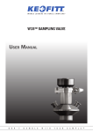
KEOFITT REFLEX™ SAMPLING VALVE User Manual S O M E P E O P L E W O U L D N ’ T G A M B L E W I T H T H E I R S A M P L E T M INTRODUCTION: MANUFACTURER: TYPE: PATENTS: YEAR OF INTRODUCTION: YEAR OF REVISED DESIGN: Keofitt A/S, Lumbyvej 11H 5000 Odense C Denmark KEOFITT REFLEX SAMPLING VALVE EP1690038 2007 - CONTENTS Presentation....................................................................................................................................................................7 Valve function.................................................................................................................................................................7 Everyday use of the valve...............................................................................................................................................8 Sterilisation........................................................................................................................................................................... 8 Sampling............................................................................................................................................................................... 8 Technical Data................................................................................................................................................................9 Keofitt Reflex™ Pneumatic Valves............................................................................................................................. 10 Parts and accessories for Keofitt Reflex™................................................................................................................ 12 Mounting instructions................................................................................................................................................. 13 Location:..............................................................................................................................................................................13 Before welding:...................................................................................................................................................................13 Welding instructions................................................................................................................................................... 13 Maintenance................................................................................................................................................................ 14 Spare parts list...................................................................................................................................................................14 Disassembly and assembly of valve body and head.......................................................................................................14 Membranes.................................................................................................................................................................. 15 PRESENTATION The Keofitt Reflex™ sampling valve is a unique 2-in-1 valve which can be readily sterilised and which meets both hygienic and process design requirements. This means that an effective cleaning and sterilisation of the sampling valve can be carried out between random samples independently of the course of the production process without compromising the same. The valve is 3-A and EHEDG Type El authorised. 3-A Sanitary Standard is an American standard which is normative for a component’s ease of cleaning and sterilisation. The standard ensures optimum conditions for food products which may come into contact with the component in question. The EHEDG Type El certification is a European standard and it includes additional tests of bacterial increase on components that are in direct contact with the sample after the CIP process. The valve is used in a wide range of processing industries, such as breweries, dairies, and the pharmaceutical and biotechnological industries. VALVE FUNCTION The valve is designed to regularly take representative random samples in the production process. The valve is therefore designed such that effective cleaning, sterilisation and sampling can be carried out regularly without interrupting the production process. Sterilisation is carried out by supplying steam through the steam inlet of the valve. It is the perfect, hygienic design and surface finish of the inner part of the valve which enables absolute sterilisation in a closed state. According to an EHEDG-based test carried out by the Biotechnological Institute in Denmark, the valve is sterilised after just 1 minute’s supply of steam at a pressure of 2 bar(g) (121°C). Following sterilisation the valve is opened and the liquid will run out of the lower hose piece. Note! The membrane functions both as a dynamic sample seal in the valve seat and as a hygienic, static steam seal against the valve body. UNIQUE! � The Keofitt Reflex valve controls both sample and steam supply. Also it eliminates the risk and waste involved with product going into the steam connection of other designs. WARNING! � During sterilisation with steam the valve will become hot, and care should thus be taken when handling the valve. � The valve is designed for use in working conditions of up to 6 bar(g) pressure and temperatures of up to 121°C. It is therefore important to be aware that the rubber plug (designed for max. 3 bar(g)) or the steel plug (designed for max. 10 bar(g)) can be forced out at high speed if not fitted correctly. � Always remember to use safety goggles when taking samples because of the risk to the eyes. IMPORTANT! � The valve cannot be used for vacuum since the membrane will be sucked hard into the seat. � The membranes are available in three different qualities: silicone, EPDM and PTFE. � The silicone membrane has the advantage that it in general can stand higher temperatures, but it cannot tolerate moisture condensation resulting from steam sterilisation. � The EPDM membrane is better able to cope with condensation in the steam, and at the same time can be used with a majority of CIP fluids. � The PTFE membrane resists most CIP fluids and very high steam temperatures. K E O F I T T U S E R M A N U A L P A G E 7 EVERYDAY USE OF THE VALVE Sterilisation Sterilisation takes place with valve in steam mode. 1. Open the steam supply and let it flow through the valve for sterilisation. 1 min. at 121°C (2 bar(g)). 2. Close the steam supply. WARNING! � During sterilisation with steam the valve will become hot, and care should thus be taken when handling the valve. � The valve is designed for use in working conditions of up to 6 bar(g) and temperatures of up to 121°C. Always remember to use safety goggles when taking samples because of the risk to the eyes. � Use saturated steam without condensation at max. 2 bar(g). At higher pressures the membrane can be damaged/split. In most cases the coaxial design ensures absolute cleanliness without the use of CIP or similar. If CIP is used, please refer to enclosed data sheet. If in doubt, contact Keofitt. IMPORTANT! � To reach 121ºC a pressure of 2 bar(g) is needed. This can only be reached by use of a pressure release valve, or other counter pressure device mounted on the outlet connection. Sampling 1. Open the valve and take the sample. 2. Shut the valve after the sample has been taken. 3. Clean the valve with steam and/or hot water, cf. ’sterilisation’, points 1-4. K E O F I T T Sterilisation U S E R M A N U A L Sampling P A G E 8 TECHNICAL DATA Material Valve body: AISI 316L (1.4404) Valve head: AISI 316L (1.4404) Membrane: Silicone (grey) EPDM (black) PTFE (white) Certificate Valve body: 3.1 Membrane silicone acc. to FDA & BGA Membrane EPDM acc. to FDA & BGA Membrane PTFE acc. to FDA & BGA ® * A 6-digit code is marked on the valve body. This code refers to a 3.1 certificate which accompanies every consignment of valve bodies, certificates are available on www.keofitt.dk Pressure - max. Working pressure: 6 bar(g) / 87 psi(g) Rubber plug 3 bar(g) / 44 psi(g) Steel plug 10 bar(g) / 145 psi(g) Temperature - max. Sterilisation temp.: 121°C / 249,80°F ** ** It is important that the steam is saturated, but dry, as condensation can damage the membrane. (Dry steam at max. 2 bar(g)). Surface finish Internal: Ra <0,5 µm/20 µinch External: Electropolished Every valve is Ra measured. A serial number identifies each valve body. A surface finish certificate copy is available. Viscosity: Viscosity range: 0-1000cP, with particles up to 3mm in diameter. Kv:�� Valve capacity [m3/h] Cv:�� Valve capacity [USgal/min] Q: �� Flow through valve seat [m3/h] p: �� Viscosity of fluid [kg/m3] p: �� Presure drop across valve [bar] K E O F I T T U S E R M A N U A L P A G E 9 KEOFITT REFLEX™ PNEUMATIC VALVES Hose piece Mini tri-clamp Welding liner Silicone 880001 880006 880007 EPDM 880001E 880006E 880007E PTFE 885501 885501 885507 B C D A B C D A B C D 7 mm 38 mm 8 mm 25 mm 7 mm 38 mm 8 mm 12,7 mm 9,4 mm 38 mm 8 mm Key measurements (Please refer to bottom page 11!) A 14 mm Tank welding (type T) - process connection Pipe welding - (type P) - process connection Silicone 880011 880010 800017 EPDM 880011E 880010E 880017E PTFE D A B C D A B C D 38 mm 8 mm 25 mm 7 mm 38 mm 8 mm 12,7 mm 9,4 mm 38 mm 8 mm 885517 C 7 mm 885510 B 14 mm Key measurements (Please refer to bottom page 11!) 885511 A Clamp - connection 1” - process connection B C D A B C D A B C D 9,4 mm 50,4 mm 8 mm Key measurements (Please refer to bottom page 11!) A 12,7 mm 885527 8 mm 885522 50,4 mm 885521 7 mm PTFE 25 mm 880027E 8 mm 880027 880022E 50,4 mm 880022 880021E 7 mm 880021 EPDM 14 mm Silicone Clamp - connection 2” - process connection K E O F I T T U S E R M A N U A L D A B C D A B C D 8 mm C 64 mm B 9,4 mm Key measurements (Please refer to bottom page 11!) A 12,7 mm On request 8 mm 885505 64 mm 885503 7 mm PTFE 25 mm On request 8 mm On request 880005E 64 mm 880005 880003E 7 mm 880003 EPDM 14 mm Silicone P A G E 1 0 Hose piece Mini tri-clamp Welding liner 885532 885537 Varivent® connection Ø50 - process connection 885508 Key measurements (Please refer to bottom page 11!) A B C D 8 mm 880008E PTFE 50 mm EPDM 7 mm 880008 14 mm Silicone Varivent® connection Ø68 - process connection 885509 Key measurements (Please refer to bottom page 11!) A B C D 8 mm 880009E PTFE 68 mm EPDM 7 mm 880009 14 mm Silicone Ingold® connection Silicone U S E R D A B 25 mm 8 mm 12,7 mm 7 mm C D 7 mm C 215 mm 165 mm K E O F I T T B 7 mm Key measurements (Please refer to bottom page 11!) A 25 mm PTFE 25 mm EPDM M A N U A L P A G E 1 1 PARTS AND ACCESSORIES FOR KEOFITT REFLEX™ K E O F I T T U S E R Item Material Ident no. Remark Membrane EPDM black EPDM 880052 Membrane silicone grey Silicone 880051 Membrane teflon Teflon 880055 Rubber cap with knob 600062 Adjustable pressure relief valve (0-3 Bar(g)) 850059 Quick coupling steel pipe 800070 Quick coupling for PTFE 800071 Quick coupling with 3/8” Hose Barb 800082 Sampling coil with st.st. cap 800058 Quick coupling with M4 hose piece 800086 O-ring Silicone 600825 O-ring Silicone 880830 M A N U A L P A G E 1 2 MOUNTING INSTRUCTIONS Location: The valve should always be located with its centre line in a horizontal or lower position. The valve will then be selfdraining. Valves centre line Before welding: Remember to disassemble the valve body and head. The valve body and head must be separated during welding. Rubber plugs, chain and membrane must be removed from the valve body, as otherwise heat from the welding process will damage them. WELDING INSTRUCTIONS Valves for welding are available in two types: T (tank) and P (pipe). 1. For type T (tank) it is necessary to drill a hole ø28 mm into the tank wall, and then fit the valve into this hole flush with the inside of the tank. Welding should be carried out as a penetration welding. Material thickness less than 4 mm: Weld from inside. Material thickness greater than 4 mm: Weld from both outside and inside. Since type T has a solid end piece, the valve will not be damaged by penetration welding. However, the use of purge gas in the form of either Argon or Formier gas is recommended in order to give the best result. 2. For type P (pipe) penetration welding must be carried out from outside. The valve is machined with a recess-like shoulder on the outside of the end piece which gives approximately the same material thickness (1.5mm material thickness) as in the pipe wall. IMPORTANT! � When grinding/polishing the internal weld, the valve seat must not be touched. The welding result will be best if the following method is used: A collar is made on the pipe section so that the valve has a flat contact face. This flaring must look like a T-piece, as shown in the example below. � The pipe section and the valve’s hose pieces are sealed with sponge rubber or similar. � Purge gas such as Argon or Formier gas is fed through the valve body into the pipe section and the system is now filled with 6 times the estimated volume of the pipe section. All O2 is thus expelled from the system and welding can commence. � Welding can take place with the purge gas continually flowing in the system. � The gas remains in the system until the item is lukewarm, after which the set-up can be dismantled. K E O F I T T U S E R M A N U A L P A G E 1 3 MAINTENANCE The rubber membrane should be replaced every two months. PTFE membranes should be replaced every 12 months. In the event of intensive sterilisation and cleaning it may be necessary to replace it more frequently. The rubber plug must be replaced at least once every six months. In each individual case a standard operating procedure including maintance intervals should be endorsed based on experience. For disassembly of valve body and valve head, see instructions. Spare parts Pos. Item 1. O-ring 2. Membrane Silicone (grey) Membrane EPDM (black) Membrane PTFE (White) Disassembly and assembly of valve body and head ‘ ORDER OF OPERATION: Remember! When replacing the membrane, set the valve head in the open position before disassembling from the body. Omitting to do so may result in twisting and cutting of the membrane. 1. Set the valve head at the open position. 2. Remove the valve head pos. 1. This is carried out by loosening the clamp and then pulling the valve head off. 3. Refit the valve head (in the open position) once the necessary parts have been replaced. K E O F I T T U S E R M A N U A L P A G E 1 4 SILICONE MEMBRANE - ITEM NO. 880051 MEMBRANES TECHNICAL SPECIFICATION � � � � � � � Type: Colour: Resistance to chemicals acids/bases) Food safe Temp. max. Steam pressure max. Process pressure Silicone Grey Suitable Yes (FDA*) 130-250°C / 266-482°F 2 bar/29 psi 1-6 bar/14-87 psi Keofitt recommends to change the silicone membrane 4-6 times a year or as needed. The recommendation is based on 1-5 samples a day, but should reflect individual tear and wear from individual cleaning and sterilisation procedures. *FDA approved compound according to Code of Federal Regulations Title 21 - § 177.1550 35 MM 24 MM K E O F I T T U S E R M A N U A L P A G E 1 5 EPDM MEMBRANE - ITEM NO. 880052 TECHNICAL SPECIFICATION � � � � � � � Type: Colour: Resistance to chemicals acids/bases) Food safe Temp. max. Steam pressure max. Process pressure EPDM Black Very good Yes (FDA*) 130-150°C / 266-302°F 2 bar/29 psi 1-6 bar/14-87 psi Keofitt recommends to change the EPDM membrane 4-6 times a year or as needed. The recommendation is based on 1-5 samples a day, but should reflect individual tear and wear from individual cleaning and sterilisation procedures. *FDA approved compound according to Code of Federal Regulations Title 21 - § 177.1550 35 mm 24 mm K E O F I T T U S E R M A N U A L P A G E 1 6 PTFE MEMBRANE - ITEM NO. 880055 TECHNICAL SPECIFICATION � � � � � � � Type: Colour: Resistance to chemicals acids/bases) Food safe Temp. max. Steam pressure max. Process pressure PTFE White Excellent** Yes (FDA*) 130-250°C / 266-482°F 2 bar/29 psi 1-6 bar/14-87 psi Keofitt recommends to change the PTFE membrane once a year or as needed. The recommendation is based on 1-5 samples a day, but should reflect individual tear and wear from individual cleaning and sterilisation procedures. 24,9 mm INSTRUCTIONS ON REPLACING PTFE MEMBRANE 1. 2. 3. 4. 5. 6. Open valve. Remove the valve head from the valve body. Push the membrane upwards until the tool for membrane fits under it. Insert tool for membrane, between the membrane and the bushing. Close valve head. Now the membrane is loosened from the valve head and can be replaced. 48,5 mm *FDA approved compound according to Code of Federal Regulations Title 21 - § 177.1550 ** Is not attacked by common chemicals, with the exception of strongly oxidising acids. To attach new membrane to valve head. 7. Set the valve head to closed position. 8. Place the new membrane on valve head. 9. Mount the membrane bushing with the new Teflon membrane by pressing the membrane with your hand until it clicks. 10. Set the valve head in open position. 11. Insert the valve head into the valve body. 12. Close valve head. IMPORTANT � Once the membrane has been removed from the valve head the click system in the membrane might be damaged. Therefore the membrane might be unsafe for further use and it is recommended not to use the membrane again. � Do not use hammer or other tool that might scratch the surface of the membrane. Tool for membrane item no. 600255 K E O F I T T U S E R M A N U A L P A G E 1 7 Keofitt reserves the right to change technical data without notice! For complete set of updated data sheets and manuals for Keofitt products please refer to our web page www.keofitt.dk