1
User Manual
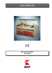
Wall of Flame
FF-Series
Issued: 11/01 Technical changes reserved!
:FFUserManual
Fejl! Brug fanen Startside til at anvende Überschrift 1 på teksten, der skal vises her. Seite 3
1 Contents
1
2
3
4
5
6
Contents ................................................................................................................................... 3
Important References ............................................................................................................... 4
2.1 Basic safety instructions ..................................................................................................... 4
2.2 Warranty and Liability ......................................................................................................... 5
2.3 Explaination of Symbols and notes for the user .................................................................. 5
2.4 Right of origin (Copyright)................................................................................................... 5
2.5 Special safety notes for the user ........................................................................................ 6
Product information ................................................................................................................... 8
3.1 Introduction ........................................................................................................................ 8
3.2 Special Features ................................................................................................................ 8
3.3 Technical Data ................................................................................................................... 8
Initial Installation Procedure .................................................................................................... 14
4.1 Unpacking ........................................................................................................................ 14
4.2 Installation ........................................................................................................................ 14
4.3 Electrical connection......................................................................................................... 15
4.4 Gas connection ................................................................................................................ 15
4.5 Re-adjustment .................................................................................................................. 16
4.6 Waste Water Connection ................................................................................................. 17
4.7 Preparation of Using / Starting up..................................................................................... 17
Operation ................................................................................................................................ 18
5.1 Operation elements .......................................................................................................... 18
5.2 Operation ......................................................................................................................... 19
Maintenance ........................................................................................................................... 20
6.1 Cleaning and care ............................................................................................................ 20
6.2 Maintenance of gastechnical parts ................................................................................... 21
6.3 Changing parts ................................................................................................................. 21
6.4 Trouble shooting ............................................................................................................... 23
6.5 Wiring Diagram ................................................................................................................ 24
6.6 Spareparts ........................................................................................................................ 25
Issued: 11/01 Technical changes reserved!
:FFUserManual
2 Important References
2.1 Basic safety instructions
2.1.1 Please read advices in the operation manual carefully
• It is important to have knowledge of the basic safety instructions and of your local safety regulations.
• This operation manual contains the most important advices to operate the appliance in the right
safe way.
• We suggest that all operating personnel will follow both, this manual and especially these safety
advices carefully.
• Please follow also the safety instructions issued by your local authorities.
2.1.2 Obligation of the owner/user
The owner/user declares, that he only allows the following personnel to operate the Wall of Flame
Rotisserie:
• People being trained to operate this appliance and do know the regulations about basic safety
instructions and how to prevent possible accidents.
• People who know about the safety chapter and the warnings within this operation manual. They
have to confirm by signing.
These obligations are subject to be checked on a regular basis.
2.1.3 Obligation of the operating personnel
Personnel, being requested to operate this appliance, hereby confirm the following:
• That they know about the basic safety instructions and do know the regulations how to prevent
possible accidents.
• That they have read the safety chapter and warnings in this operation manual and they have
confirmed with their signature having understood all information.
2.1.4 How to use the Rotisseries. Possible risks.
Wall of Flame Rotisseries are built following the latest standard of technic and according to all
safety regulations. However while operating in case of not following all safety instructions, they
may cause severe risks for the operators and other people‘s life. They may also cause possible
damages to the appliance. Therefore the appliance is only for the use of:
• Operation according to the designed purpose of a rotisserie.
• Being in optimal safe and technical conditions.
All malfunctions, which may effect the safety of the appliance must be repaired immediately.
2.1.5 Operation according to the designed purpose
All Wall of Flame Rotisseries are built for the preparation of food only. Any other use of the unit
are only allowed after consulting UBERT GASTROTECHNIK GMBH. Damages which result out of
wrong use UBERT GASTROTECHNIK GMBH cannot be held responsible. Part of the due use is
also:
•
•
the consideration of all references of the operating manual and
the observance of neccessary maintenance and service.
Issued: 11/01 Technical changes reserved!
:FFUserManual
Fejl! Brug fanen Startside til at anvende Überschrift 1 på teksten, der skal vises her. Seite 5
2.2 Warranty and Liability
All products from the manufacturer are manufactured to the high nowadays technical standards
and comply with all valid regulations. The manufacturer will grant a warranty to compensate all
recognized valid claims. All other Warranty and Liability claims for people and appliances are excluded, especially if a possible damage is caused:
• In case of any improper use not according to the designed purpose.
• In case of wrong installation, incorrect setting into operation, wrong treatment and maintenance
of the appliance.
• In case of operating the appliance with faulty, missing or not working safety features.
• By disregarding of the operation manual advices especially in the view of transport, storage,
installation, setting into operation, operation and maintenance.
• By changing the appliance without any written permission.
• By changing the power dates without any written permission.
• In the case of non regular maintenance of any parts being subject to wear and tear.
• In case of nonprofessional service.
• In case of any force majeure.
2.3 Explaination of Symbols and notes for the user
Within this operation manual you will find the following signs and symbols:
This symbol stands for a possible danger for life and health. It also points out to a
possible hazardous situation.
To disregard this symbols may cause severe hazardous effects up to severe injuries. It may also cause severe damages to your appliance!
This symbol will give important notes to the user how to treat the appliance in the
right way.
To disregard this symbols may cause a possible damage to your appliance or to the
environment!
This symbol will give you useful tips and advices.
They will help you in using all functions of the appliance in the best way!
2.4 Right of origin (Copyright)
The copyright on this operation manual remains strictly with the manufacturer. It is only issued for
the owner and his trained personnel. This manual contains regulations and advices which either in
parts or the full brochure may not be:
• duplicated
• circulated or
• used or announced for a different purpose.
Violation may cause criminal prosecution.
Issued: 11/01 Technical changes reserved!
:FFUserManual
2.5 Special safety notes for the user
2.5.1 Safety devices (Protection units)
• Before setting the appliance into operation all safety devices and all removable
parts have to be fitted and must operate in working order.
• Safety devices may only be removed after switching off the appliance completely.
You must make sure, that the appliance cannot be switched on again during maintenance processes.
• All parts and components have to be fitted according to the regulations.
2.5.2 For your information (Informing safety steps)
• These operating instructions shoud be kept always together with the appliance.
• Supplementing to the operation instructions within this manual all local regulations
for accident prevention and for the protection of the enviroment are to be considered.
• All stickers for safety and possible hazards on the appliance have to be in a good
readable condition and in a visible position.
2.5.3 Personnel training
• Only trained and instructed personnel is allowed to operate the appliance.
• The responsibilities of the personnel are to be determined clearly for installing, startup, operation, assembling, and servicing of the unit.
• Personnel not being trained yet are only allowed to operate the unit under supervision of a trained and experienced person.
2.5.4 Operating the controls
• Only trained personnel is allowed to operate the controls.
2.5.5 Safety check during operation
• Only operate the appliance if all safety devices are working properly.
• Before switching on, make sure that there is no danger for any person while the
appliance is starting to operate.
• Check appliance at least once per day with regard to visible damages and to the
function of all safety devices.
2.5.6 Possible hazards caused by electric energy
• Repair works on electrical leads and devices must be carried out by qualified electricians only.
• The connection must follow the rules of the local determinations.
• Check the electrical components of the appliance on a regular basis. Wiring being
connected improper or melted cables have to be repaired immediately.
• If there is a need of repair works on life electrical components, always a second
person is required to attend and to switch off the main switch in case of emergency.
2.5.7 Special areas of danger
• All removable parts are only to be removed if the Wall of Flame Rotisserie is
switched off and all surfaces and parts are not hot anymore!
• Caution while removing grilled food! All parts may be hot and may cause severe
burnings to your skin. Do not reach into the rotisserie while the appliance is hot and
operating. Before removing the waste fat pan take out the waste liquids.
Issued: 11/01 Technical changes reserved!
:FFUserManual
Fejl! Brug fanen Startside til at anvende Überschrift 1 på teksten, der skal vises her. Seite 7
2.5.8 Maintenance, Trouble Shooting
• All prescribed adjustment-, maintenance- and serviceworks must be carried out by
an authorized service technician on a regular basis.
• Before starting these maintenance- and service works the personnel must be clearly
informed.
• Pull out the plug before maintaining, inspecting and repairing is performed.
• Make sure that all loose screw connections are fixed and secured again.
• Check all safety devices and their proper function carefully at the end of all maintenance-, service and repair works.
2.5.9 Technical amendments to the appliance
• No amendments, changings or reconstructions to the appliance are allowed to be
carried out without the written permission of the manufacturer. Never weld on loadbearing parts of construction.
• All reconstructions do require a written permission of the manufacturer.
• Improper parts have to be changed immediately.
• Only use original spare parts.
• If you use spare parts of a third party, we cannot take over responsibility of their
safe construction and of any proper use in our appliances. All possible damages
caused by the use of improper parts will not be covered by the manufacturer.
• In case of reconstructions which impair the supply of air for combusion, the function
of the unit has to be examined again.
2.5.10 Cleaning and waste disposal
All matters and materials should be used only in accordance with their purpose. Used
materials, especially those for lubricating and cleaning must be disposed in accordance with the valid regulations. Only use detergents which are in accordance with the
food hygienic regulations, environmental regulations and the regulations issued by
your local authorities.
Issued: 11/01 Technical changes reserved!
:FFUserManual
3 Product information
3.1 Introduction
The most important feature of the FF-series rotisseries is the high functionality with very attractive
optical effects. That guarantees an optimum food processing and presentation, which is the basis
for every selling success.
3.2 Special Features
•
•
•
•
•
•
Enamelled execution
Optimum grilling result due to movable spits
Heat storing cast iron or steel radiators
Elegant design by metal decoration
Excellent flame optical effect by glowing glass filaments
Illumination by halogen light
3.3 Technical Data
3.3.1 Capacity
Depending on the size up to 6 chickens per spit.
3.3.2 Dimensions [mm]
Model
WxHxD
Number of Spits:
FF - 22:
FF - 24:
FF - 26:
FF - 28:
FF - 32:
FF - 34:
FF - 36:
FF - 38:
FF - 42:
FF - 44:
FF - 46:
FF - 48:
1120 x 1000 x 675
1120 x 1515 x 675
1120 x 2030 x 675
1120 x 2545 x 675
1450 x 1000 x 675
1450 x 1515 x 675
1450 x 2030 x 675
1450 x 2545 x 675
1780 x 1000 x 675
1780 x 1515 x 675
1780 x 2030 x 675
1780 x 2545 x 675
2
4
6
8
2
4
6
8
2
4
6
8
3.3.3 Weight [kg]
Model
Net weight:
FF - 22:
FF - 24:
FF - 26:
FF - 28:
FF - 32:
FF - 34:
FF - 36:
FF - 38:
FF - 42:
FF - 44:
FF - 46:
FF - 48:
ca 210kg
ca 290kg
ca 340kg
ca 410kg
ca 280kg
ca 380kg
ca 440kg
ca 510kg
ca 380kg
ca 445kg
ca 495kg
ca 565kg
3.3.4 Electrical Details, Power Consumption, Noise Emission
Type
el. connection [EA]
power cons.
all types
230V, 1/N, 50Hz
0.7 kW
Issued: 11/01 Technical changes reserved!
noise emission
< 70 dB (A)
:FFUserManual
Fejl! Brug fanen Startside til at anvende Überschrift 1 på teksten, der skal vises her. Seite 9
3.3.5 Nozzle table
Model
Kind of gas
FF 22
FF 22
FF 22
FF 22
FF 22
FF 24
FF 24
FF 24
FF 24
FF 24
FF 26
FF 26
FF 26
FF 26
FF 26
FF 28
FF 28
FF 28
FF 28
FF 28
FF 32
FF 32
FF 32
FF 32
FF 32
FF 34
FF 34
FF 34
FF 34
FF 34
FF 36
FF 36
FF 36
FF 36
FF 36
FF 38
FF 38
FF 38
FF 38
FF 38
Fluid gas 50mbar
Fluid gas 30mbar
Natural gas H
Natural gas L
Natural gas E+
Fluid gas 50mbar
Fluid gas 30mbar
Natural gas H
Natural gas L
Natural gas E+
Fluid gas 50mbar
Fluid gas 30mbar
Natural gas H
Natural gas L
Natural gas E+
Fluid gas 50mbar
Fluid gas 30mbar
Natural gas H
Natural gas L
Natural gas E+
Fluid gas 50mbar
Fluid gas 30mbar
Natural gas H
Natural gas L
Natural gas E+
Fluid gas 50mbar
Fluid gas 30mbar
Natural gas H
Natural gas L
Natural gas E+
Fluid gas 50mbar
Fluid gas 30mbar
Natural gas H
Natural gas L
Natural gas E+
Fluid gas 50mbar
Fluid gas 30mbar
Natural gas H
Natural gas L
Natural gas E+
Number Size of
Size of minimum Opening of
Size of nozzle
of
main
nozzles [mmx100] primary air
ignition burner
main
nozzles
[mm]
[mmx100]
nozzles [mmx100]
=number
of burners
1
130
80 (screwed tightly)
open
20 (screwed tightly)
1
140
90 (screwed tightly)
open
20 (screwed tightly)
1
240
50 (adjustable)
open
35 (adjustable)
1
260
50 (adjustable)
open
35 (adjustable)
1
240
50 (adjustable)
open
35 (adjustable)
2
130
80 (screwed tightly)
open
20 (screwed tightly)
2
140
90 (screwed tightly)
open
20 (screwed tightly)
2
240
50 (adjustable)
open
35 (adjustable)
2
260
50 (adjustable)
open
35 (adjustable)
2
240
50 (adjustable)
open
35 (adjustable)
3
130
80 (screwed tightly)
open
20 (screwed tightly)
3
140
90 (screwed tightly)
open
20 (screwed tightly)
3
240
50 (adjustable)
open
35 (adjustable)
3
260
50 (adjustable)
open
35 (adjustable)
3
240
50 (adjustable)
open
35 (adjustable)
4
130
80 (screwed tightly)
open
20 (screwed tightly)
4
140
90 (screwed tightly)
open
20 (screwed tightly)
4
240
50 (adjustable)
open
35 (adjustable)
4
260
50 (adjustable)
open
35 (adjustable)
4
240
50 (einstellbar)
open
35 (einstellbar)
2
130
80 (screwed tightly)
open
20 (screwed tightly)
2
140
90 (screwed tightly)
open
20 (screwed tightly)
2
210
50 (adjustable)
open
35 (adjustable)
2
230
50 (adjustable)
open
35 (adjustable)
2
210
50 (adjustable)
open
35 (adjustable)
4
130
80 (screwed tightly)
open
20 (screwed tightly)
4
140
90 (screwed tightly)
open
20 (screwed tightly)
4
210
50 (adjustable)
open
35 (adjustable)
4
230
50 (adjustable)
open
35 (adjustable)
4
210
50 (adjustable)
open
35 (adjustable)
6
130
80 (screwed tightly)
open
20 (screwed tightly)
6
140
90 (screwed tightly)
open
20 (screwed tightly)
6
210
50 (adjustable)
open
35 (adjustable)
6
230
50 (adjustable)
open
35 (adjustable)
6
210
50 (adjustable)
open
35 (adjustable)
8
130
80 (screwed tightly)
open
20 (screwed tightly)
8
140
90 (screwed tightly)
open
20 (screwed tightly)
8
210
50 (adjustable)
open
35 (adjustable)
8
230
50 (adjustable)
open
35 (adjustable)
8
210
50 (einstellbar)
open
35 (einstellbar)
Issued: 11/01 Technical changes reserved!
:FFUserManual
FF 42 Fluid gas 50mbar
2
130
80 (screwed tightly)
open
20 (screwed tightly)
FF 42 Fluid gas 30mbar
2
140
90 (screwed tightly)
open
20 (screwed tightly)
FF 42 Natural gas H
2
240
50 (adjustable)
open
35 (adjustable)
FF 42 Natural gas L
2
260
50 (adjustable)
open
35 (adjustable)
FF 42 Natural gas E+
2
240
50 (adjustable)
open
35 (adjustable)
FF 44 Fluid gas 50mbar
4
130
80 (screwed tightly)
open
20 (screwed tightly)
FF 44 Fluid gas 30mbar
4
140
90 (screwed tightly)
open
20 (screwed tightly)
FF 44 Natural gas H
4
240
50 (adjustable)
open
35 (adjustable)
FF 44 Natural gas L
4
260
50 (adjustable)
open
35 (adjustable)
FF 44 Natural gas E+
4
240
50 (adjustable)
open
35 (adjustable)
FF 46 Fluid gas 50mbar
6
130
80 (screwed tightly)
open
20 (screwed tightly)
FF 46 Fluid gas 30mbar
6
140
90 (screwed tightly)
open
20 (screwed tightly)
FF 46 Natural gas H
6
240
50 (adjustable)
open
35 (adjustable)
FF 46 Natural gas L
6
260
50 (adjustable)
open
35 (adjustable)
FF 46 Natural gas E+
6
240
50 (adjustable)
open
35 (adjustable)
FF 48 Fluid gas 50mbar
8
130
80 (screwed tightly)
open
20 (screwed tightly)
FF 48 Fluid gas 30mbar
8
140
90 (screwed tightly)
open
20 (screwed tightly)
FF 48 Natural gas H
8
240
50 (adjustable)
open
35 (adjustable)
FF 48 Natural gas L
8
260
50 (adjustable)
open
35 (adjustable)
FF 48 Natural gas E+
8
240
50 (einstellbar)
open
35 (einstellbar)
For the Netherlands with connection pressure 25 mbar for natural gas the nozzle size (main nozzle) is: 220 [mmx100]
Issued: 11/01 Technical changes reserved!
:FFUserManual
Fejl! Brug fanen Startside til at anvende Überschrift 1 på teksten, der skal vises her. Seite 11
3.3.6 Indication of consumption
Model
Kind of gas
FF 22
FF 22
FF 22
FF 22
FF 22
FF 24
FF 24
FF 24
FF 24
FF 24
FF 26
FF 26
FF 26
FF 26
FF 26
FF 28
FF 28
FF 28
FF 28
FF 28
FF 32
FF 32
FF 32
FF 32
FF 32
FF 34
FF 34
FF 34
FF 34
FF 34
FF 36
FF 36
FF 36
FF 36
FF 36
FF 38
FF 38
FF 38
FF 38
FF 38
Fluid gas
Natural gas H
Natural gas L
Natural gas E+ 20mbar
Natural gas E+ 25mbar
Fluid gas
Natural gas H
Natural gas L
Natural gas E+ 20mbar
Natural gas E+ 25mbar
Fluid gas
Natural gas H
Natural gas L
Natural gas E+ 20mbar
Natural gas E+ 25mbar
Fluid gas
Natural gas H
Natural gas L
Natural gas E+ 20mbar
Natural gas E+ 25mbar
Fluid gas
Natural gas H
Natural gas L
Natural gas E+ 20mbar
Natural gas E+ 25mbar
Fluid gas
Natural gas H
Natural gas L
Natural gas E+ 20mbar
Natural gas E+ 25mbar
Fluid gas
Natural gas H
Natural gas L
Natural gas E+ 20mbar
Natural gas E+ 25mbar
Fluid gas
Natural gas H
Natural gas L
Natural gas E+ 20mbar
Natural gas E+ 25mbar
Max.
Min.
Consumption Consumption Consumption
Nominal Nominal flow of Fluid flow Natural flow Natural
Heat Heat Load
gas on
gas H on
gas L on
Load
[kW]
HuB=12,68
HuB=9,45
HuB=8,125
[kW]
kwh/kg
kwh/m³
kwh/m³
[kg/h]
[m³/h]
[m³/h]
10
3,47
0,79
/
/
10
2,83
/
1,05
/
10
3,04
/
/
1,23
10
2,83
/
1,05
/
9
2,33
/
1,05
/
20
6,93
1,58
/
/
20
5,65
/
2,11
/
20
6,08
/
/
2,46
20
5,65
/
2,11
/
18
4,67
/
2,11
/
30
10,4
2,37
/
/
30
8,48
/
3,17
/
30
9,12
/
/
3,69
30
8,48
/
3,17
/
27
7
/
3,17
/
40
13,87
3,15
/
/
40
11,31
/
4,23
/
40
12,16
/
/
4,93
40
11,31
/
4,23
/
36
9,33
/
4,23
/
15
5,2
1,18
/
/
15
4,24
/
1,58
/
15
4,56
/
/
1,85
15
4,24
/
1,58
/
13,5
3,5
/
1,58
/
30
10,4
2,37
/
/
30
8,48
/
3,17
/
30
9,12
/
/
3,69
30
8,48
/
3,17
/
27
7
/
3,17
/
45
15,6
3,55
/
/
45
12,72
/
4,75
/
45
13,68
/
/
5,54
45
12,72
/
4,75
/
40,5
10,5
/
4,75
/
60
20,8
4,73
/
/
60
16,96
/
6,34
/
60
18,24
/
/
7,39
60
16,96
/
6,34
/
54
14
/
6,34
/
Issued: 11/01 Technical changes reserved!
:FFUserManual
FF 42
FF 42
FF 42
FF 42
FF 42
FF 44
FF 44
FF 44
FF 44
FF 44
FF 46
FF 46
FF 46
FF 46
FF 46
FF 48
FF 48
FF 48
FF 48
FF 48
Fluid gas
Natural gas
Natural gas
Natural gas
Natural gas
Fluid gas
Natural gas
Natural gas
Natural gas
Natural gas
Fluid gas
Natural gas
Natural gas
Natural gas
Natural gas
Fluid gas
Natural gas
Natural gas
Natural gas
Natural gas
H
L
E+ 20mbar
E+ 25mbar
H
L
E+ 20mbar
E+ 25mbar
H
L
E+ 20mbar
E+ 25mbar
H
L
E+ 20mbar
E+ 25mbar
20
20
20
20
18
40
40
40
40
36
60
60
60
60
54
80
80
80
80
72
Issued: 11/01 Technical changes reserved!
6,94
5,66
6,08
5,66
4,66
13,86
11,3
12,16
11,3
9,34
20,8
16,96
18,24
16,96
14
27,74
22,62
24,32
22,62
18,66
1,58
/
/
/
/
3,16
/
/
/
/
4,74
/
/
/
/
6,3
/
/
/
/
/
2,1
/
2,1
2,1
/
4,22
/
4,22
4,22
/
6,34
/
6,34
6,34
/
8,46
/
8,46
8,46
/
/
2,46
/
/
/
/
4,92
/
/
/
/
7,38
/
/
/
/
9,86
/
/
:FFUserManual
Fejl! Brug fanen Startside til at anvende Überschrift 1 på teksten, der skal vises her. Seite 13
3.3.7 Valid categories for the use of the Wall of Flame Rotisserie
Country
Germany
Austria
Italy
Portugal
Spain
Sweden
Switzerland
Netherland
Danmark
Finland
Ireland
Great Britain
Norway
Belgium
France
Iceland
Czech Republic
Country Specification
DE:
AT:
IT:
PT:
ES:
SE:
CH:
NL:
DK:
FI:
IE:
GB:
NO:
BE:
FR:
IS
CZ
Category
II2ELL3B/P
II2H3B/P
I2H
I2H
I2H
II2H3B/P
II2H3B/P
II2L3P, II2L3B/P
II2H3B/P
II2H3B/P
I2H
I2H
II2H3B/P
I2E I3P
II2E+3B/P
II2H3B/P
II2H3B/P
Pressure Gasconnect
20, 50 mbar
20, 50 mbar
20 mbar
20 mbar
20 mbar
20, 30 mbar
20, 50 mbar
25, 30, 50 mbar
20, 30 mbar
20, 30 mbar
20 mbar
20 mbar
20, 30 mbar
20, 50 mbar
20/25, 50 mbar
20, 30 mbar
20, 30 mbar
3.3.8 Type Plate
The installation and operation manual is made for the Ubert Wall of Flame Rotisserie of the model
series FF with the categories of natural and fluid gas mentioned under point 3.3.8. The units correspond to kind of construction "A".
The type plate is fixed on the front side of the unit and bears the following indications:
- Serial number, type
- Order number kind of construction acc. to DIN-EN 203
A B
- Applicable for natural gas H/L and fluid gas
- Categorie
- Adjusted for natural gas H 20 mbar
- for natural gas L 20 mbar
- for fluid gas mbar
- Heat Load kW
- Adjustment pressure pressure control mbar
- Consumption: natural gas H m³/h
- natural gas L m³/h
- fluid gas
kg/h
- Power: kW
- Electrical connection.: V N Hz
- 0085
Differing from a.m. indications the type plate will be executed suitable for the following countries:
Netherlands for natural gas L:
connection pressure 25 mbar
France and Belgium for natural gas E+:
connection pressure 20 bzw. 25 mbar.
3.3.9 Construction of the Wall of Flame Rotisserie und equipment
The unit is a Wall of Flame Rotisserie with atmospheric main burners, pilot flame burner and
chicken spits which are driven by a motor chain gear. The gas connection is at the lower right side
of the unit. The temperature control is made by multiple adjustment valves with thermoelectrical
ignition safety device (fully ignition safe gas armatures) The operation temperature can be adjusted infinitely variable from the minimum adjustment to the maximum adjustment. Each burner is
ignited separately by a piezo igniter. Motor and illumination are switched on or off by turning cam
switches.
Issued: 11/01 Technical changes reserved!
:FFUserManual
4 Initial Installation Procedure
Our Wall of Flame Rotisseries are packed for safe transport, so that they can reach
their destination without any damages. However we advise an examination of the Wall
of Flame Rotisserie right after delivery.
Attention! Do report visible damages immediately!
4.1 Unpacking
• Open the box and take out the wrapping and filling material carefully.
• Take out all single parts and check whether these are complete (compare with enclosed dispatch documents).
• Now please remove the cardboard packaging and all wrapping and covering folios from the
rotisserie.
4.2 Installation
4.2.1 General information
• Install the feet of the unit and set it up at the place as wanted.
• Set up the unit on an even, horizontal surface! Line up the unit horizontal.
• Observe that all slots for air supply and ventilation are held free and are at least 100
mm away from walls or similar things which could block the slots.
• Take care that the area around the rotisserie is free in order to load, unload, clean
the unit or that maintenance works can be done smoothly.
• The unit has to be set up in a way that the surrounding area can be cleaned.
4.2.2 Place of operation
Attention! The rotisserie has to be set up on an even, stable and fireproof surface in a
good ventilated room and below an existing ventilation hood. Depending on the model
the unit can be placed free in a room or at a temperature-resistant wall or in one line
with other equipment. A minimum distance of 200 mm from walls made of inflammable material has to be observed. If these distances fall below corresponding heat protection measures have to be made, for instance tiling of walls or application of a radiation protection. Before you install the unit check the type plate, whether the unit is approved for the the local existing kind of gas. If the kind of gas indicated on the type
plate does not agree with the required kind of gas, the installation of the rotisserie is
not allowed until the unit has been adjusted according to the requirements.
4.2.3 Statutory orders, technical regulations and directions
The following regulations have to be observed when the unit is set up:
•
•
•
•
local statutory orders
local laws valid for your countries
technical regulations for fluid gas
directions of the local gas supply company
Furthermore regulations of accident prevention valid for your country have to be observed.
For operating the unit outside Germany the national laws, technical regulations and
directions of the specific country are valid.
4.2.3 Special advices regarding the gas exhaust
Attention! The rotisserie has to be set up in sufficiently ventilated rooms and below an
existing ventilation hood. The unit corresponds to kind of construction "A". The installation to an exhaust gas device (ventilation hood) is necessary in order to lead out the
exhaust gas immediately.
Issued: 11/01 Technical changes reserved!
:FFUserManual
Fejl! Brug fanen Startside til at anvende Überschrift 1 på teksten, der skal vises her. Seite 15
4.2.4 Installation
Before the unit can be installed it is necessary to have the comments / approvement of
the responsible gas supply company.
Only a installation company which is approved by the responsible gas supply company
is allowed to set up the unit, install the gas connection and to start the operation. The
laws, technical regulations and directions mentioned under section 4.2.3 have to be
observed. Only approved companies are allowed to do maintenance work or gas adjustments and they have to observe this manual and corresponding regulations.
4.3 Electrical connection
Note! Note that also after installation and electrical connection the plug must be accessible. If this is not possible due to structural reasons, or if the unit is connected
permanently, the power supply needs to have an interlock switch.
Note! During any servicing, take care that the unit is disconnected from the mains!
Not paying attention may result in injury!
Please learn the electrical and technical data of your unit from the nameplate.
•
•
•
The unit is ready for plug-in.
For power supply a shockproof socket is necessary.
Make sure the supply cable is protected separatly with 16 Amps.
The existing connection cable for the electrical connection is positioned at the lower
right rear wall.
Note!
After finishing any installationwork, maintainance or repair check whether the ground
wires are connected properly to the casing.
4.4 Gas connection
Check whether the gas unit is adjusted for the existing kind of gas. Compare the indicated kind of gas on the type plate with the existing kind of gas. If this is not the case
an adjustment according to the local requirements is necessary. The gas connection
depends on the rotisserie model (external thread right acc. to DIN-ISO 7/1 [DIN 2999,
part 1] 1 inch). The connection with the gas supply has to be made through the intermediary of a connection armature and through a thermically secured shutoff device.
Technical regulations have to be observed. Only an approved technician is allowed to
do this work. After the gas connection has been made all points of connection have to
be tested for leaks under operation pressure by leak detecting spray or by brushing
with foam forming mediums which do not cause corrosion.
4.4.1 Preparation for operation
The units have to be checked on their designed nominal heat load and adjusted accordingly if required when they are installed the first time or after any maintenance work. This has to be made.
Please learn the necessary values from the table in section 3.3.7.
4.4.2 Control of nominal heat load
Firstly, please check whether the unit is adjusted for the existing kind of gas. For this you have to
check whether the indication on the type plate corresponds to the existing kind of gas. If you adjust
the unit for other gas types please check the indication of the nozzles. The nominal heat load results from using the right nozzle with connection pressure of
+ 20 mbar with natural gas H and natural gas L (for France E+)
+ 50 mbar with fluid gas
by taking effect of the corresponding tuyère area.
Issued: 11/01 Technical changes reserved!
:FFUserManual
The permission of operation with the resulting nominal heat load under dependency of the planned
nozzles results from the following connection pressure bounds:
15 to 25 mbar with natural gases)
25 to 35 mbar and 42.5 to 57.5 mbar with fluid gas
Starting the operation outside these pressure bounds is not permitted.
The connection pressure is measured by a pressure gauge (indication exactness: 0.1 mbar). For
this the sealing screw in the connection pressure measuring socket of the main gas supply has to
be loosened and the pressure gauge has to be connected.
4.4.3 Checking of nominal heat load with fluid gas
Check whether the indication of used nozzles corresponds to the indications of the manufacturer.
Secure that the existing low pressure regulator on site does not exceed a maximum output pressure of 50 mbar according to section 4.4.2 (control of type plate or pressure measurement).
4.4.4 Control of function
• Set the unit into operation according to the manual.
• Check the unit for gas leaks.
• Check the correct adjustment of primary air and nozzles (pilot flame device, main nozzles (at
the burner nozzle assembly), minimum adjustment nozzles (at the all gas valve).
• Check the transmission ignition and regularly flames of the burners with minimum and maximum adjustment.
• A maintenance contract is recommended.
4.5 Re-adjustment
Attention! Before any re-adjustment works at the unit are executed the main gas
supply has to be closed and the unit has to be unpluged firstly.
All units of our production are single examined and are adjusted for the kind of gas required by the
customer. If no indication has been made, the units are principally adjusted for fluid gas. If the unit
is to be re-adjusted it has to be observed that this is made by an approved technician or by the
Ubert service technicians. The corresponding nozzles sizes are to be find in the nozzle table. For
re-adjustment the following measures have to be made:
•
•
•
•
•
Replacement of pilot flame nozzles.
Replacement of main nozzles.
Replacement of bypass nozzle
Adjustment of primary air.
Checking of function and indication of new gas type on the type plate at the front of the unit.
4.5.1 Replacement of pilot flame nozzle (pilot flame device)
• Close the main gas supply and unplug the unit.
• Remove the side walls after unscrewing them.
• Remove the ignition cable from the ignition plug at the pilot flame.
• Unscrew the ignition plug from the pilot flame device.
• Unscrew the gas supply connected to the pilot flame device.
• Remove the thermo feeler.
• Unscrew the pilot flame device.
• Unscrew the nozzle after removal of the union and replace it according to the nozzle table.
The assembling is to be made in reversed sequence. Afterwards the function has to be checked.
Issued: 11/01 Technical changes reserved!
:FFUserManual
Fejl! Brug fanen Startside til at anvende Überschrift 1 på teksten, der skal vises her. Seite 17
4.5.2 Replacement of main nozzle
• Close the main gas supply and unplug the unit.
Access from the front side of the unit:
• Remove the spits and fat drawers
• Remove the ribs as follows:
1. Push the rib upwards.
2. Push the lower rib to the rear.
3. Pull the rib downwards.
4. Remove the rib to the front.
Access from the rear side of the unit
• Remove the rear wall after unscrewing it.
• Remove the burner nozzle assembly from the injector case (cast iron part) after unscrewing the
fixing screw at the injector case and the union of the gas supply from the all gas valve.
• Unscrew the main nozzle from the burner nozzle assembly and replace it according to the nozzle table.
The re-assembling is to be made in reversed sequence. Afterwards check the function.
4.5.3 Replacement of bypass- / minimum adjustment nozzle
• Remove the lower fat drawer and the bottom plate.
• Pull off the control knobs from the operation panel.
• Pull off the ignition cable from all piezo ignitors.
• Remove the front/operation panel carefully after unscrewing it.
• The minimum adjustment nozzle is to be find at the upper front side of the all gas valve.
• Unscrew the minimum adjustment nozzle and replace it according to the nozzle table.
The re-assembling is to be made in reversed sequence. Afterwards check the function.
4.5.4 Adjustment of minimum position
For fluid gases and natural gases please learn the size of minimum adjustment nozzle from the
nozzle table. The corresponding nozzles have to be turned against the stop.
4.6 Waste Water Connection
The water drain of the fat drawer is at the right front. You should drain the fluids/fat
coming out of the food products through the ball valve before you remove fat drawer
for cleaning.
4.7 Preparation of Using / Starting up
Before setting your Rotisserie Wall of Flame into operation, please clean all removable parts with
a fat-solving detergent. After cleaning you may dry all surfaces.
Warning! Do not use any flammable Liquids for cleaning. Neither clean your Compact
Rotisserie with high pressure cleaning devices, nor use steam or water-jet-cleaning!
You will find further detailled information about cleaning and maintenance in the special chapter within this manual.
By cleaning your Rotisserie Wall of Flame before first use you will avoid smells and smoke and
you start using your rotisserie in a hygenic and safe way.
Issued: 11/01 Technical changes reserved!
:FFUserManual
5 Operation
5.1 Operation elements
Following you find explanantions regarding all important position and function components for the
operation of the unit:
1.
2.
3.
4.
5.
6.
7.
8.
Spit
Fat Drawer
Gear chain
Spit support
Control knob
Rotation switch
Light switch
Ball drain cock
for taking up the grill products
catches the meat juice and fat coming out of the grill product
sets the spit in rotation
used as outer support of spit.
used for adjustment of the gas burner
switches on or off the spit gear
switches on or off the illumination as well as the ventilation
used for draining fluids out of the fat drawer
Issued: 11/01 Technical changes reserved!
:FFUserManual
Fejl! Brug fanen Startside til at anvende Überschrift 1 på teksten, der skal vises her. Seite 19
5.2 Operation
Please observe the following check list for starting the operation of the unit.
Attention! The ignition process takes place principally from downwards to upwards.
• For igniting you have to turn the knob one eighth (1/8) rotation to the
left towards the ignition symbol.
• Then push the knob up to the stop so that the gas flows out.
• For ignition push the key of the piezo igniter.
• After the ignition still push the knob for approx. 15 – 20 seconds.
• For minimum adjustment you have to turn the knob counter-clockwise.
• Turn the knob on position 0 in order to switch off the main burner.
When you adjust the spit distances please observe that the spits are moved parallel to
the burner in order to achieve an even product result and in order not to overstrain the
the spit gear motor.
5.2.1 Optional: Equipped with glass doors
Information: To allow thermal expansion of the glass doors, the hings are designed with large
tolerances. Maybe because of that the doors are not parallel to each other.
Issued: 11/01 Technical changes reserved!
:FFUserManual
6 Maintenance
Following we give you advices for maintenance, possible trouble shooting and for service cases of
your unit.
6.1 Cleaning and care
6.1.1 Safety advices
• Before you start any cleaning or maintenance work close the main gas supply and
unplug the unit.
• Never use flammable liquids, nor use any sharp or metallic utensils for cleaning
your appliance. Do not use high pressure water or steam appliances! More detailed
information to follow below.
• Wear acidproof gloves while cleaning the parts to prevent skin irritations.
6.1.2 General Recommendations
• The unit has to be cleaned daily.
• Only use non-poisonous cleaners(neutral or alkaline detergents) which are harmless in connection with food, even if there are plain and persistent residues.
• After cleaning with special cleaners you have to wash all parts with clear water and
dry them afterwards so that there are no residues of the cleaner on these parts.
• It is absolutely necessary to watch out for some fundamental things to keep this
longliving high-grade-steel-machine working:
- always keep the high-grade-steel surface clean.
- watch out that there is always enough fresh air on the surface
- never contact the surface with rusty material
• never use bleaching or chlorine cleaners.
• Observe that no residues or waste reaches the burner or thermo element during
operation or cleaning, as this can cause damages to the proper function of the
burner.
6.1.3 Special Recommendations
Control the grease lubrication of the bearings and the chain at least quarterly, if necessary more often. If the bearings and the chain are not greasy enough, grease
them to ensure a reliable working of the bearing. For lubrication use heat-resistant
grease only. Disregarding follows defect bearings and breakdown of the spit rotation!
(Heat-resistant grease (part no. 412221) and grease guns (part no. 550408) are
available at Ubert.)
6.1.4 Detergents
To make the cleaning fast and easy we have integrated some cleaners in our program:
• Stainless steel-cleaner
You have to spray this from a distance of app. 25 cm on the surface and wipe it off
with a dry cleaning rag. If you want to clean only small parts you have to spray it directly on the cleaning rag and wipe it off this way. With this method it is possible to
clean the Rotisserie Wall of Flame easily and without stripes..
Issued: 11/01 Technical changes reserved!
:FFUserManual
Fejl! Brug fanen Startside til at anvende Überschrift 1 på teksten, der skal vises her. Seite 21
6.1.5 Daily Cleaning
1. Let the unit cool down.
(down to ambience temperature).
2. Unplug the unit.
3. Close the main gas supply.
4. Remove the spits.
5. Catch the drain water.
(Water remaining from the cleaning catch up in the fat drawers).
6. Clean the removed parts.
• The stainless steel parts should be cleaned daily with soapy water, rinsed with clear water and
dried carefully.
• If the unit is not used for a longer time the stainless steel parts should be greased with vaseline
oil.
6.2 Maintenance of gastechnical parts
The unit has to be checked regularly on perfect function by an approved service technician.
After re-adjustments, maintenance works or after dismounting the unit the unit has to be checked
on perfect function. Possible faults have to be eliminated immediately. Check whether the actual
regulations have been observed with regard to technical appliances and operation locations.
Especially the following has to be checked:
• Function of existing control and safety devices.
• Examination of burning reaction after ignition reaction and burning safety (If the nozzles or
bores of the main burner are narrowed, you have to clean or replace them.)
• Is the burner in fixed position.
• Check the function (see 1.5.3)
For maintenance please observe especially the following points :
6.2.1 Burner
For burner maintenance check the following points and eliminate the faults.
• Check the general condition with regard to fixings, damages.
• Fixing of burner nozzle assembly.
• Burner outlets: are the tuyères narrowed by waste or anything else they have to be cleaned in
any case.
• Check the primary air area with regard to any waste.
• Check the function of ignition safety.
6.2.2 Burner reaction
Checking of the burner reaction has to be made by sight and function control. The flames have to
burn stable and not yellow, not to lift up or flash back.
6.2.3 Heat Load and Test for leakages
For this check the right nozzles and the correct connection pressure. Further make a leakage test.
6.3 Changing parts
Everytime you replace any parts at the unit you have to close the main gas supply and to unplug
the unit. After you have finished the work you have to control the function (acc. to section 1.5.3)!
6.3.1 Piezo igniter
• Remove the lower fat drawer and the bottom plate.
• Remove the ignition cable from the piezo igniter.
• You can remove and replace the piezo igniter by loosening the fixing nut from the front panel.
The re-installation is to be made in reversed sequence.
Issued: 11/01 Technical changes reserved!
:FFUserManual
6.3.2 Ignition plug
The ignition plug at the pilot flame burner can be replaced acc. to section 1.6.1.
6.3.3 Thermo element
• Remove the lower fat drawer and the bottom plate.
• Remove the corresponding side wall after you have unscrewed it.
• Remove the thermo element from the pilot flame device (see 1.6.1)
• Remove the thermo element union from the all gas valve.
The assembling is to be made in reversed sequence.
6.3.4 Pilot flame device
See section 1.6.1. The gas lead between the all gas valve and pilot flame device can be removed
by loosening of the unions of these both parts.
6.3.5 Burner
• Remove the spits and the fat drawer in front of the burner which has to be replaced.
• Close the main gas supply and unplug the unit.
Access from the front side of the unit:
• Remove the spits and fat drawers
• Remove the ribs as follows:
5. Push the rib upwards.
6. Push the lower rib to the rear.
7. Pull the rib downwards.
8. Remove the rib to the front.
Access from the rear side of the unit
• Remove the rear wall after unscrewing it.
•
• Remove the burner nozzle assembly from the injector case (cast iron part) after unscrewing the
fixing screw at the injector case and the union of the gas supply from the all gas valve.
• Remove the injector and the tube angle from the burner socket.
• Loosening of the 3 unions between burner and the support profile below the burner.
• Remove the burner.
The re-assembling is to be made in reversed sequence.
6.3.6 All gas valve
• Remove the lower fat drawer and the bottom plate.
• Remove the thermo element from the main gas supply and from the gas lead to the burner by
loosening the unions.
• Remove the thermo element from the all gas valve. ( The connection of the thermo element is
behind the all gas valve.)
• Remove the all gas valve from the main gas supply and from the gas lead to the burner after
loosening of the unions.
• Remove the all gas valve.
The re-assembling has to be made in reversed sequence.
6.3.7 Motor
• Remove the lower fat drawer and the bottom plate.
• Loosen the 2 screws from the protection plate above the motor and remove it.
• Unplug the motor.
• Loosen the chain tension union from the support of the motor (is to be find in front of the motor).
• Remove the support with motor after you have removed the hinge pin and the gear wheel of the
gear shaft from the chain.
• Loosen 4 X screws between the motor and the support and remove the motor.
The re-assembling is to be made in reversed sequence.
Issued: 11/01 Technical changes reserved!
:FFUserManual
Fejl! Brug fanen Startside til at anvende Überschrift 1 på teksten, der skal vises her. Seite 23
6.4 Trouble shooting
If your Rotisserie Wall of Flame does not work satisfactorily we would like to give a first help with
the following checklist. Only after checking these points you should contact:
a) your responsible service partner
or
b)
directly the company:
UBERT GASTROTECHNIK GmbH
Werk II Gewerbegebiet Nord
Vennekenweg 17
46348 Raesfeld
Tel.:(49) 02865 / 602-226
Service-Tel.:0172 / 2 82 86 31
Fax:(49) 02865 / 602-102 (oder -103)
Only these two companies are allowed to carry out service work and replacement of
defect parts. If you do not observe this note or in case of manipulation of a third party
any claims for guarantee will become invalid!
6.4.1 Trouble Shooting
If you have problems with processing the grill products or generally with the operation of the unit,
please check firstly the following points:
Failure
Possible reason
Solution
Uneven flames
burner is narrowed
supply of primary air does work
correctly
main nozzle is narrowed
Clean the burner
Protect from draft
Call the service
Spit rotates hardly
spits are not adjusted parallel
Re-adjust the spits
Spit does not rotate
motor is not switched on
Protective circuit breaker has
released
Switch on the motor
Push the protective circuit
breaker gear 1 x
motor is defect
Call the service
Lamp is not switched on
otherwise
Lamp defect
Switch on the lamp
otherwise
Call the service
Illumination does not work
Issued: 11/01 Technical changes reserved!
:FFUserManual
6.5 Wiring Diagram
6.5.1 all versions
230V / 50Hz / 1Ph N
Issued: 11/01 Technical changes reserved!
:FFUserManual
Fejl! Brug fanen Startside til at anvende Überschrift 1 på teksten, der skal vises her. Seite 25
6.6 Spareparts
Replace defect or faulty parts only by using our original spare parts. Repairworks and
changing of any parts must be carried out by authorized service personell. Disregarding these advices will cause a loss of any warranty claims. Also all certificates (as
there are: CE, UL, VDE, GS and others) will not be valid anymore!
6.6.1 List of Spare Parts
Issued: 11/01 Technical changes reserved!
:FFUserManual
26
Fejl! Brug fanen Startside til at anvende Überschrift 1 på teksten, der skal vises her.
FF24
Description
scale light / motor
scale gas valve
drive shaft
burner
cast iron fin
ball-handle Ø30
ball-handle Ø50
spit support
grommet 10x12x18
lamp socket
halogen-lamp
ON / OFF-switch light / motor
plug
plug-drive motor
coupling drive.motor
overcurrent release
gas valve
temperature probe (M8) 1500mm
temperature probe (M8) 850mm
switch element for push button
push button
ignition-transformer
pilot flame burner
ignition-electrode
nozzle (Ø1.15mm propane)
logo plate
leg assy
knob
drive motor
chain, brass plaked
chain drive motor
chain sprocket
chain sprocket with bearing
chain sprocket drive motor
chain sprocket (cast iron) spit
bearing drive shaft
ignition cable for piezo ignitor 1,3m
Part No. Amount
360203
2
360215
2
180596
1
180590
2
180577
4
301953
4
301955
2
306800
8
333105
3
340412
2
340620
1
341115
2
341301
1
341302
1
341401
1
342602
1
352125
2
352327
1
352328
1
380242
1
380244
1
380260
1
352512
2
352513
2
352673
2
360180
1
361096
4
361310
6
380103
1
380500
9,51
380505
2,5
380508
1
380513
1
380516
1
380525
8
380601
4
180710
1
ignition cable for piezo ignitor 1,75m
180711
printed: 12/2012 Subject to change!
1
FFUserManual
Fejl! Brug fanen Startside til at anvende Überschrift 1 på teksten, der skal vises her.
27
FF26
Description
Part No. Amount
scale light / motor
360203
2
scale gas valve
360215
3
drive shaft
180596
1
burner
180590
3
cast iron fin
180577
6
ball-handle Ø30
301953
6
ball-handle Ø50
301955
4
spit support
306800
12
grommet 10x12x18
333105
3
lamp socket
340412
2
halogen-lamp
340620
1
ON / OFF-switch light / motor
341115
2
plug
341301
1
plug-drive motor
341302
1
coupling drive.motor
341401
1
overcurrent release
342602
1
gas valve
352125
3
temperature probe (M10) 1500mm
352326
2
temperature probe (M8) 1500mm
352327
2
temperature probe (M8) 850mm
352328
2
2
temperature probe extension (M8-M10) 352329
600mm
switch element for push button
380242
1
push button
380244
1
ignition-transformer
380260
1
pilot flame burner
352512
3
ignition-electrode
352513
3
nozzle (Ø1.15mm propane)
352673
3
logo plate
360180
1
leg assy
361096
4
knob
361310
8
drive motor
380103
1
chain, brass plaked
380500
11,07
chain drive motor
380505
3,9
chain sprocket
380508
1
chain sprocket with bearing
380513
1
chain sprocket drive motor
380516
1
chain sprocket (cast iron) spit
380525
12
bearing drive shaft
380601
4
ignition cable for piezo ignitor 1,3m
180710
1
ignition cable for piezo ignitor 1,75m
180711
1
ignition cable for piezo ignitor 2,2m
180712
1
printed: 12/2012 Subject to change!
FFUserManual
28
Fejl! Brug fanen Startside til at anvende Überschrift 1 på teksten, der skal vises her.
FF28
Description
Part No. Amount
scale light / motor
360203
2
scale gas valve
360215
4
drive shaft
180596
1
burner
180590
4
cast iron fin
180577
8
ball-handle Ø30
301953
8
ball-handle Ø50
301955
6
spit support
306800
16
grommet 10x12x18
333105
3
lamp socket
340412
2
halogen-lamp
340620
1
ON / OFF-switch light / motor
341115
2
plug
341301
1
plug-drive motor
341302
1
coupling drive.motor
341401
1
overcurrent release
342602
1
gas valve
352125
4
temperature probe (M10) 1500mm
352326
2
temperature probe (M8) 1500mm
352327
1
temperature probe (M8) 850mm
352328
1
temperature probe extension (M8-M10) 352329
3
600mm
switch element for push button
380242
1
push button
380244
1
ignition-transformer
380260
1
pilot flame burner
352512
4
ignition-electrode
352513
4
nozzle (Ø1.15mm propane)
352673
4
logo plate
360180
1
leg assy
361096
4
knob
361310
10
drive motor
380103
1
chain, brass plaked
380500
12,63
chain drive motor
380505
5,3
chain sprocket
380508
1
chain sprocket with bearing
380513
1
chain sprocket drive motor
380516
1
chain sprocket (cast iron) spit
380525
16
bearing drive shaft
380601
4
ignition cable for piezo ignitor 1,3m
180710
1
ignition cable for piezo ignitor 1,75m
180711
ignition cable for piezo ignitor 2,2m
180712
1
ignition cable for piezo ignitor 2,8m
180713
1
printed: 12/2012 Subject to change!
1
FFUserManual
Fejl! Brug fanen Startside til at anvende Überschrift 1 på teksten, der skal vises her.
29
FF34
Description
scale light / motor
scale gas valve
drive shaft
burner left
cast iron fin
burner right
ball-handle Ø30
ball-handle Ø50
spit support
grommet 10x12x18
lamp socket
halogen-lamp
ON / OFF-switch light / motor
plug
plug-drive motor
coupling drive.motor
overcurrent release
gas valve
temperature probe (M8) 1500mm
temperature probe (M8) 850mm
switch element for push button
push button
ignition-transformer
pilot flame burner
ignition-electrode
nozzle (Ø1.15mm propane)
logo plate
leg assy
knob
drive motor
chain, brass plaked
chain drive motor
chain sprocket
chain sprocket with bearing
chain sprocket drive motor
chain sprocket (cast iron) spit
bearing drive shaft
ignition cable for piezo ignitor 1,3m
Part No. Amount
360203
2
360215
4
180543
1
180570
2
180577
6
180580
2
301953
4
301955
2
306800
8
333105
3
340412
2
340620
1
341115
2
341301
1
341302
1
341401
1
342602
1
352125
4
352327
2
352328
2
380242
1
380244
1
380260
1
352512
4
352513
4
352673
4
360180
1
361096
4
361310
6
380103
1
380500
9,51
380505
2,5
380508
1
380513
1
380516
1
380525
8
380601
4
180710
2
ignition cable for piezo ignitor 1,75m
180711
printed: 12/2012 Subject to change!
2
FFUserManual
30
Fejl! Brug fanen Startside til at anvende Überschrift 1 på teksten, der skal vises her.
FF36
Description
Part No. Amount
scale light / motor
360203
2
scale gas valve
360215
6
drive shaft
180543
1
burner left
180570
3
cast iron fin
180577
9
burner right
180580
3
ball-handle Ø30
301953
6
ball-handle Ø50
301955
4
spit support
306800
12
grommet 10x12x18
333105
3
lamp socket
340412
2
halogen-lamp
340620
1
ON / OFF-switch light / motor
341115
2
plug
341301
1
plug-drive motor
341302
1
coupling drive.motor
341401
1
overcurrent release
342602
1
gas valve
352125
6
temperature probe (M10) 1500mm
352326
2
temperature probe (M8) 1500mm
352327
2
temperature probe (M8) 850mm
352328
2
temperature probe extension (M8-M10) 352329
2
600mm
switch element for push button
380242
1
push button
380244
1
ignition-transformer
380260
1
pilot flame burner
352512
6
ignition-electrode
352513
6
nozzle (Ø1.15mm propane)
352673
6
logo plate
360180
1
leg assy
361096
4
knob
361310
8
drive motor
380103
1
chain, brass plaked
380500
11,07
chain drive motor
380505
3,9
chain sprocket
380508
1
chain sprocket with bearing
380513
1
chain sprocket drive motor
380516
1
chain sprocket (cast iron) spit
380525
12
bearing drive shaft
380601
4
ignition cable for piezo ignitor 1,3m
180710
2
ignition cable for piezo ignitor 1,75m
180711
2
ignition cable for piezo ignitor 2,2m
180712
2
printed: 12/2012 Subject to change!
FFUserManual
Fejl! Brug fanen Startside til at anvende Überschrift 1 på teksten, der skal vises her.
31
FF38
Description
Part No. Amount
scale light / motor
360203
2
scale gas valve
360215
8
drive shaft
180543
1
burner left
180570
4
cast iron fin
180577
12
burner right
180580
4
ball-handle Ø30
301953
8
ball-handle Ø50
301955
6
spit support
306800
16
grommet 10x12x18
333105
3
lamp socket
340412
2
halogen-lamp
340620
1
ON / OFF-switch light / motor
341115
2
plug
341301
1
plug-drive motor
341302
1
coupling drive.motor
341401
1
overcurrent release
342602
1
gas valve
352125
8
temperature probe (M10) 1500mm
352326
2
temperature probe (M8) 1500mm
352327
2
temperature probe (M8) 850mm
352328
2
temperature probe extension (M8-M10) 352329
6
600mm
switch element for push button
380242
1
push button
380244
1
ignition-transformer
380260
1
pilot flame burner
352512
8
ignition-electrode
352513
8
nozzle (Ø1.15mm propane)
352673
8
logo plate
360180
1
leg assy
361096
4
knob
361310
10
drive motor
380103
1
chain, brass plaked
380500
12,63
chain drive motor
380505
5,3
chain sprocket
380508
1
chain sprocket with bearing
380513
1
chain sprocket drive motor
380516
1
chain sprocket (cast iron) spit
380525
16
bearing drive shaft
380601
4
ignition cable for piezo ignitor 1,3m
180710
2
ignition cable for piezo ignitor 1,75m
180711
ignition cable for piezo ignitor 2,2m
180712
2
ignition cable for piezo ignitor 2,8m
180713
2
printed: 12/2012 Subject to change!
2
FFUserManual
32
Fejl! Brug fanen Startside til at anvende Überschrift 1 på teksten, der skal vises her.
FF44
Description
scale light / motor
scale gas valve
drive shaft
burner
cast iron fin
ball-handle Ø30
ball-handle Ø50
spit support
grommet 10x12x18
lamp socket
halogen-lamp
ON / OFF-switch light / motor
plug
plug-drive motor
coupling drive.motor
overcurrent release
gas valve
temperature probe (M8) 1500mm
temperature probe (M8) 850mm
switch element for push button
push button
ignition-transformer
pilot flame burner
ignition-electrode
nozzle (Ø1.15mm propane)
logo plate
leg assy
knob
drive motor
chain, brass plaked
chain drive motor
chain sprocket
chain sprocket with bearing
chain sprocket drive motor
chain sprocket (cast iron) spit
bearing drive shaft
ignition cable for piezo ignitor 1,3m
Part No. Amount
360203
2
360215
4
180597
1
180590
4
180577
8
301953
4
301955
2
306800
8
333105
3
340412
2
340620
1
341115
2
341301
1
341302
1
341401
1
342602
1
352125
4
352327
2
352328
2
380242
1
380244
1
380260
1
352512
4
352513
4
352673
4
360180
1
361096
4
361310
6
380103
1
380500
9,51
380505
2,5
380508
1
380513
1
380516
1
380525
8
380601
4
180710
2
ignition cable for piezo ignitor 1,75m
180711
printed: 12/2012 Subject to change!
2
FFUserManual
Fejl! Brug fanen Startside til at anvende Überschrift 1 på teksten, der skal vises her.
33
FF46
Description
Part No. Amount
scale light / motor
360203
2
scale gas valve
360215
6
drive shaft
180597
1
burner left
180590
6
cast iron fin
180577
12
ball-handle Ø30
301953
6
ball-handle Ø50
301955
4
spit support
306800
12
grommet 10x12x18
333105
3
lamp socket
340412
2
halogen-lamp
340620
1
ON / OFF-switch light / motor
341115
2
plug
341301
1
plug-drive motor
341302
1
coupling drive.motor
341401
1
overcurrent release
342602
1
gas valve
352125
6
temperature probe (M10) 1500mm
352326
2
temperature probe (M8) 1500mm
352327
2
temperature probe (M8) 850mm
352328
2
temperature probe extension (M8-M10) 352329
2
600mm
switch element for push button
380242
1
push button
380244
1
ignition-transformer
380260
1
pilot flame burner
352512
6
ignition-electrode
352513
6
nozzle (Ø1.15mm propane)
352673
6
logo plate
360180
1
leg assy
361096
4
knob
361310
8
drive motor
380103
1
chain, brass plaked
380500
11,07
chain drive motor
380505
3,9
chain sprocket
380508
1
chain sprocket with bearing
380513
1
chain sprocket drive motor
380516
1
chain sprocket (cast iron) spit
380525
12
bearing drive shaft
380601
4
ignition cable for piezo ignitor 1,3m
180710
2
ignition cable for piezo ignitor 1,75m
180711
2
ignition cable for piezo ignitor 2,2m
180712
2
printed: 12/2012 Subject to change!
FFUserManual
34
Fejl! Brug fanen Startside til at anvende Überschrift 1 på teksten, der skal vises her.
FF48
Description
Part No. Amount
scale light / motor
360203
2
scale gas valve
360215
8
drive shaft
180597
1
burner left
180590
8
cast iron fin
180577
16
ball-handle Ø30
301953
8
ball-handle Ø50
301955
6
spit support
306800
16
grommet 10x12x18
333105
3
lamp socket
340412
2
halogen-lamp
340620
1
ON / OFF-switch light / motor
341115
2
plug
341301
1
plug-drive motor
341302
1
coupling drive.motor
341401
1
overcurrent release
342602
1
gas valve
352125
8
temperature probe (M10) 1500mm
352326
2
temperature probe (M8) 1500mm
352327
2
temperature probe (M8) 850mm
352328
2
temperature probe extension (M8-M10) 352329
6
600mm
switch element for push button
380242
1
push button
380244
1
ignition-transformer
380260
1
pilot flame burner
352512
8
ignition-electrode
352513
8
nozzle (Ø1.15mm propane)
352673
8
logo plate
360180
1
leg assy
361096
4
knob
361310
10
drive motor
380103
1
chain, brass plaked
380500
12,63
chain drive motor
380505
5,3
chain sprocket
380508
1
chain sprocket with bearing
380513
1
chain sprocket drive motor
380516
1
chain sprocket (cast iron) spit
380525
16
bearing drive shaft
380601
4
ignition cable for piezo ignitor 1,3m
180710
2
ignition cable for piezo ignitor 1,75m
180711
2
ignition cable for piezo ignitor 2,2m
180712
2
ignition cable for piezo ignitor 2,8m
180713
2
printed: 12/2012 Subject to change!
FFUserManual