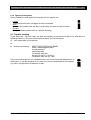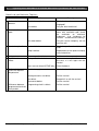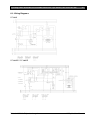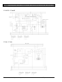
1
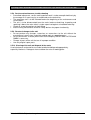
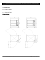
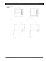
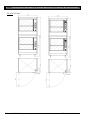
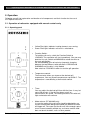
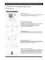
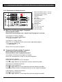
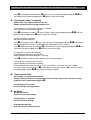
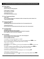
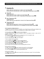
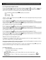
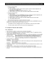
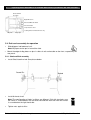
User Manual
Rotisseries „Top Line“
RT - Series
Fejl! Brug fanen Startside til at anvende Überschrift 1 på teksten, der skal vises her.
3
1 Contents
1
2
3
4
5
6
Contents ................................................................................................................................... 3
Important References ............................................................................................................... 4
2.1 Fundamental Safety Notes ................................................................................................. 4
2.2 Warranty and Liabilities ...................................................................................................... 5
2.3 Symbols and Notes ............................................................................................................ 5
2.4 Copyright ............................................................................................................................ 5
2.5 Special safety references ................................................................................................... 6
Introduction ............................................................................................................................... 8
3.1 Technical details ................................................................................................................. 8
Installation and starting the operation ..................................................................................... 12
4.1 Unwrapping ...................................................................................................................... 12
4.2 Installation ........................................................................................................................ 12
4.3 Electrical connection......................................................................................................... 12
4.4 Preparation of Operation / Starting up .............................................................................. 13
Operation ................................................................................................................................ 14
5.1 Operation of rotisseries equipped with manual controls only ............................................ 14
5.2 Operation of rotisseries equipped with digital electronic ................................................... 15
5.3 Component Function and Location ................................................................................... 21
5.4 Rotisserie assembly for operation .................................................................................... 22
5.5 Product mounting and loading .......................................................................................... 24
Maintenance ........................................................................................................................... 26
6.1 Cleaning and care ............................................................................................................ 26
6.2 Trouble shooting ............................................................................................................... 27
6.3 Wiring Diagrams ............................................................................................................... 29
6.4 Spare Parts ...................................................................................................................... 32
Printed: 12/2012 Subject to change!
TopLineUserManual
4
Fejl! Brug fanen Startside til at anvende Überschrift 1 på teksten, der skal vises her.
2 Important References
2.1 Fundamental Safety Notes
2.1.1 Consider notes in the operating manual
Precondition for the safe and trouble free use of this unit is the knowledge of the fundamental safety
notes and safety regulations.
The operating instruction contains the most important references to operate the unit safely.
These operating instructions, particularly the safety references, are to be considered by all persons,
who work on the unit.
Furthermore the rules and regulations to avoid accidents are to be considered.
2.1.2 Obligation of the operator
The operator is obliged to only let persons work with the unit who:
•
•
Are familiar with the fundamental regulations of work safety and accident avoiding and who have
been instructed how to operate the unit.
Read and understood the chapter about safety and warning notes and have confirmed this by
signature.
The safe consious operation of the staff has to be examined regularly.
2.1.3 Obligation of the staff
All induviduals who are authorized to work with the unit are obliged to:
•
•
Pay attention to the fundamental regulations of work safety and accident avoiding,
Read the chapter on work safety and warning notes in this manual and to confirm through their
signature that they have understood these, before actually operating the unit.
2.1.4 Possible risks
The TopLine Rotisseries are built state of the art and in acknowledgement of all safety related rules.
Nevertheless is it possible that danger for body and lifes of the user and/or third and/or impairments
at the unit or at other real values merge. The unit is to be used only:
•
•
For the due use.
In safety related flawless condition.
Disturbances which can hurt the safety are to be eliminated immediately.
2.1.5 Due use
The TopLine Rotisseries are built exclusively for the preparation of food only. Any other use of the
unit is only allowed after consulting UBERT GASTROTECHNIK GMBH. Damages which result out
of wrong use UBERT GASTROTECHNIK GMBH cannot be held responsible. Part of the due use is
also:
•
•
The consideration of all references of the operating manual and
The observance of neccessary maintenance and service.
Printed: 12/2012 Subject to change!
TopLineUserManual
Fejl! Brug fanen Startside til at anvende Überschrift 1 på teksten, der skal vises her.
5
2.2 Warranty and Liabilities
Fundamentaly our "General terms of sale and delivery" are valid. These are known to the operator
at the latest since signing of the contract. Claims to warranty and liability at persons- and property
damages are impossible, if they are to be led back to one or several of the following causes:
•
•
•
•
•
•
•
•
Non due use of the unit.
Improper assembling, starting up, operating and servicing of the unit.
Operating the unit with defective safety devices or safety devices which have not been installed
properly and are in no working condition.
Disobeyment of the references in the operating manual concerning transportation storage,
installation, start-up, operation, maintenance and assembling of the unit.
Unauthorized mechanical or electrical changes of the unit.
Unsufficient maintenance of wear and tear parts.
Unauthorized repair.
Force of nature and act of god.
2.3 Symbols and Notes
In the operating manual the following symbols and signs are used:
This symbol means a possibly or directly threatening danger for the life and the
health of persons and/or a possibly dangerous situation.
Ignoring of these references may result in consequences for your health and/or
can lead to property damages!
This symbol points to important references for the proper use of the unit.
Not paying attention to these references can lead to disturbances of the unit or of
the environment!
This symbol points to operation tips and especially useful information.
Help to use all functions at your unit optimally
2.4 Copyright
The copyright on this operating manual remains with the company UBERT GASTROTECHNIK
GMBH. This operating manual is intended only for the operator and his staff. It contains instructions
and references which neither completely nor partially is:
• To be duplicated
• To be circulated or
• To be otherwise made available to third parties.
Offences may violate applicable laws.
Printed: 12/2012 Subject to change!
TopLineUserManual
6
Fejl! Brug fanen Startside til at anvende Überschrift 1 på teksten, der skal vises her.
2.5 Special safety references
2.5.1 Safety devices
• Before operating the unit all protective devices as well as all removable parts must
be installed correctly and be fully workable.
• Protective devices may only be removed:
• after stand still and
• Prevention of unintentional restart.
• If partial components are delivered, an authorized staff member or service technician
has to execute assembly according to installation guidelines.
2.5.2 Informal safety steps
• The operating manual is to be kept constantly accessible in the operating area.
• In addition to the operating manual all generally acknowledged and all local
regulations for accident avoiding and environmental protection have to be applied
with.
• All safety- danger labels at the unit are to be kept in readable condition.
2.5.3 Education of the staff
• Only trained and instructed staff is allowed to operate the unit.
• The responsibilities of the staff are to be determined clearly for installing, start-up,
operation, assembling, and servicing of the unit.
• During instructing the staff may only work at the unit under supervision of an
experienced person.
2.5.4 Unit-control
• Only instructed staff is allowed to operate the controls.
2.5.5 Safety during regular operation
• The unit is only to operate if all protective devices are fully workable.
• At least once per shift the unit is to be examined with regard to visible damages and
functional ability of the safety devices.
2.5.6 Dangers caused by electrical energy
• Any work on the electrical supply is to be executed only by a specialist.
• Likewise the electrical connection of this unit to the power supply must be executed
by an examined electrician; the connection must follow the rules of the local
determinations.
• The electric installation is to be examined regularly. Loose connections and brased
cabels are to be eliminated immediately.
• If works at any life-parts are necessary, a second person who switches off the main
switch if neccessary is to consult.
2.5.7 Special danger-spots
• All removable parts like spit, disc or fan cover for instance, are only to be removed if
the rotisserie is switched off and all surfaces, inner walls and parts are cold!
• Caution while removing grilled food! All parts may be hot and may cause severe
burnings to your skin.
• Do not reach into the rotisserie while the appliance is hot and operating. Keep the
doors closed at any time!
Printed: 12/2012 Subject to change!
TopLineUserManual
Fejl! Brug fanen Startside til at anvende Überschrift 1 på teksten, der skal vises her.
7
2.5.8 Service and maintenance, trouble shooting
• Prescribed adjustment, service and inspection work is to be accomplished timely by
the manager or if necessary by an authorized service technician.
• The operating staff is to be informed before the beginning of the maintenance and
service work.
• The unit is to be disconnected from the mains before maintaining, inspecting and
repairing is done; the main switch is to be supervised against unintended reclosing.
• Check all screw connections for tight fitting.
• After finishing maintenance check all safety devices for proper functionality.
2.5.9 Structural changes to the unit
• Do not perform any changes, extensions or conversions to the unit without the
manufacturer’s permission, especially welding work at supporting parts.
• For all conversions a written permission of the company UBERT GASTROTECHNIK
GMBH is necessary.
• Change all parts of the unit that are in improper condition.
• Use only original spare parts.
2.5.10 Cleaning of the unit and disposal of the waste
Used substances and materials are to be handled and disposed appropriately,
especially lubricants. Detergents have to follow the rules of food-hygiene.
Printed: 12/2012 Subject to change!
TopLineUserManual
8
Fejl! Brug fanen Startside til at anvende Überschrift 1 på teksten, der skal vises her.
3 Introduction
3.1 Technical details
3.1.1 Dimensions [mm]
RT 303 – RT 306:
Printed: 12/2012 Subject to change!
TopLineUserManual
Fejl! Brug fanen Startside til at anvende Überschrift 1 på teksten, der skal vises her.
9
RT 307 / RT 308:
Printed: 12/2012 Subject to change!
TopLineUserManual
10
Fejl! Brug fanen Startside til at anvende Überschrift 1 på teksten, der skal vises her.
RT 314 / RT 316:
Printed: 12/2012 Subject to change!
TopLineUserManual
Fejl! Brug fanen Startside til at anvende Überschrift 1 på teksten, der skal vises her.
3.1.2 Weight
Type
weight (in kg)
RT 303
RT 303S
RT 304
RT 305 / RT 306
RT 307 / RT 308
RT 314 / RT 316
ca. 92
ca. 92
ca. 92
ca. 92
ca. 169
ca. 338
3.1.3 Electrical details
Type
electrical connection [EA]
power
RT 303S
RT 303
230V, 1/N, 50Hz
400V, 3/N, 50Hz
3.5kW
5.0kW
RT 304
400V, 3/N, 50Hz
5.5kW
RT 305 / RT 306
400V, 3/N, 50Hz
6.0kW
RT 307 / RT 308
400V, 3/N, 50Hz
11.1kW
3.1.4 Noise emission
Type
noise emission
all types
< 70 dB (A)
Printed: 12/2012 Subject to change!
11
TopLineUserManual
Fejl! Brug fanen Startside til at anvende Überschrift 1 på teksten, der skal vises her.
12
4 Installation and starting the operation
In general all Rotisseries „Top Line“ will be packed for safe transport after the final
control in order to reach you properly. Nevertheless we ask you to have a look at the
machine on arrival to check on any possible transport damages.
Note! Visible damages have to be reported immediately!
4.1 Unwrapping
• Open the carton and take out the wrapping material carefully.
• Take care that the delivery is complete (see attached freight documents).
4.2 Installation
Place the Rotisserie „Top Line“ at the desired location. Make sure, that it is good
visible for your customer to ensure good food presentation and successful sales.
Take care of the following points:
• The TopLine Rotisserie (with or without stand) has to be placed on a horizontal
level. Use a spirit level if necessary.
• Note that all ventilating slots have a free space from a wall or similar of at least
10cm (app. 4 inch).
• Location underneath a ventilation system is usefull and recomended.
• There has to be enough free space to load, unload, clean and maintain the unit.
• The machine has to be placed in a way that the complete area around it can be
cleaned easily.
4.3 Electrical connection
Note! In general, only service technicians of the company: UBERT GASTROTECHNIK GMBH or service technicians of your responsible service partner are
allowed to perform el. connection and other service! All national and local rules and
regulations concerning electricity, fireprotection and similar have to be considered.
During any servicing, take care that the unit is disconnected from the mains! Not
paying attention may result in injury!
Please learn the electrical and technical data of your unit from the name plate.
•
•
•
•
Check whether your local electrical power supply is in accordance with the values on the name
plate.
The power supply needs to be manufactured from heat resistant, flexible cable. It is to be routed
to prevent any contact to hot parts.
The unit is to be connected to the power supply either by means of an appropriate plug or if
connected permanently, a switch (interrupting all poles) is to be provided. In case of an
emergency the power supply must be interruptable immediately.
For further information please see the wiring diagram (attached).
Note!
After finishing any installation work, maintainance or repairs check whether the
ground wires are connected properly to the casing.
Printed: 12/2012 Subject to change!
TopLineUserManual
Fejl! Brug fanen Startside til at anvende Überschrift 1 på teksten, der skal vises her.
13
4.4 Preparation of Operation / Starting up
Before you can operate the TopLine Rotisserie you have to clean the unit and all removable parts
(e. g. spits, discs etc) carefully with a grease solvent detergent. Afterwards you have to dry all
surfaces.
Note! Do not use flammable cleaners. Do not use high pressure-, water pressure- or
steam jet- cleaning machines. You will have further information about this in the
section ‘cleaning and maintenance’.
After cleaning the TopLine Rotisserie properly the smell will be minimal when using it the first time.
Printed: 12/2012 Subject to change!
TopLineUserManual
14
Fejl! Brug fanen Startside til at anvende Überschrift 1 på teksten, der skal vises her.
5 Operation
Following you will find explanation and location of all components and their function for the use of
the TopLine Rotisserie.
5.1 Operation of rotisseries equipped with manual controls only
5.1.1 Operating panel
Printed: 12/2012 Subject to change!
•
•
Yellow Pilot Light: Indicates heating elements are running.
Green Pilot Light: Indicates rotisserie is switched on.
•
Function Switch:
To load the rotisserie, switch the Function Switch to
LOADING. The ventilation will start immediately. You now may
load the first spit. Switch to WARMING to rotate the disks to
the next spit position.
Go ahead loading your rotisserie by frequently changing
between the two different switch positions LOADING and
WARMING until the disc is fully loaded.
Now switch to COOKING in order to start the grill operation.
•
Temperature control:
The thermostat allows you to preset the desired grill
temperature. You may choose temperatures up to 250°C. The
temperature is controlled by a thermostatic control.
•
Timer:
You may adjust the desired grill time with the timer. It may last
up to 120 minutes. If the time has been run off an
accusticalarm will sound. The heating elements will switch off,
light and rotation will continue.
•
Motor release (RT 303-305 only):
In case the motor of the rotisserie should be blocked by any
reason and therefore being overheated, the protective switch
will trigger off. Take care that the disc will have enough space
to turn around smoothly without any resistance and the food
does not touch the doors, walls or other product.
TopLineUserManual
Fejl! Brug fanen Startside til at anvende Überschrift 1 på teksten, der skal vises her.
15
5.2 Operation of rotisseries equipped with digital electronic
5.2.1 Operating panel
Printed: 12/2012 Subject to change!
•
Electronic Controller
The controller is used to automatically control the grilling time
period, grilling temperature and grilling end time.
•
Function Switch has 4 positons:
COOKING – Cooks the products.
WARMING – Keeps the product warm and the spits rotating
or can be used to position the spit disk for loading.
LOADING – Stops spit disk rotation for spit loading.
OFF – switchs the engine offline
•
Temperature control:
The temperature control sets the temperature between 38°250°C (100°-482°F) when the manual mode is being used.
•
Automatic/Manual Switch
The automatic/manual switch is set on manual control of the
temperature or is set on automatic for control of the rotisserie
using the automatic electronic controller.
•
Motor release (RT 303-305 only):
In case the motor of the rotisserie should be blocked by any
reason and therefore being overheated, the protective switch
will trigger off. Take care that the disc will have enough
space to turn around smoothly without any resistance and
the food does not touch the doors, walls or other product.
TopLineUserManual
Fejl! Brug fanen Startside til at anvende Überschrift 1 på teksten, der skal vises her.
16
5.2.2 Explanation of the digital electronic
14
13
12
11
10
15
Powered by Ubert
ubert.com
11
12
13
14
15
Multi-Function-Display (upper 7-segment):
Temperature-Display (middle 7-segment)
Time-Display (lower 7-segment)
Temperature Button
Up Button
Down Button
Core Temperature Button
Programming Button
Start/Stop Button
Time Button
Start delay LED
Time LED
Core Temperature LED
Temperature LED
Spit rotation Button
Multi-Function-Display (upper 7-segment)
Shows program number.
Shows the current program resp. is blank if the PA program is selected.
If no program is running (Standby):
Shows "Pr X“ or is blank in PA program
- X = program number 1...20
If a program is running (active):
Shows "Pr X.Y" or blank for the PA (=permanently adjustable) program
- X = programnumber 1...20
- Y = step number 1...3
Shows "End" at the end of a program
Temperature-Display (middle 7-segment)
Shows temperature at operation level.
Shows parameter name at programming level.
If no program is running and a program is selected:
Shows the set temperature of step 1 of the selected program
If PA program is selected:
Shows the set temperature of the PA program.
Push to toggle between set temperature and core temperature probe
If a program is selected and running :
Shows the actual temperature
Push to toggle between current temperature and core temperature probe
Keep pushed to show the set temperature of the current step of the program.
If PA program is selected and running :
Shows the actual temperature
Push to toggle between current temperature and core temperature probe
Printed: 12/2012 Subject to change!
TopLineUserManual
Fejl! Brug fanen Startside til at anvende Überschrift 1 på teksten, der skal vises her.
17
Push to change set temperature.( 14 starts to flash); by pushing up/down button /
the
set temperature can be changed; push again to enter the change.
Time-Display (lower 7-segment)
Shows time / start delay at operation level.
Shows parameter data at programming level.
If no program is running and a program is selected:
Total set time of the selected program.
Push to change start delay. ( 11 starts to flash); by pushing up/down button /
the start
delay can be changed; push again to enter the change.
If the PA program is selected:
Set time of the PA program
the set time
Push to change set time.( 12 starts to flash); by pushing up/down button /
can be changed. If the time is set to 00:00, the PA program will run endless.
Push again to change start delay.( 11 starts to flash); by pushing up/down button /
the
start delay can be changed; push again to enter the change.
If a program is selected and running:
Remaining delay time during start delay.
Remaining total time while program is running.
Keep pushed to show the total set time of the running program
If PA program is selected and running:
Remaining delay time during start delay.
Remaining total time while running or “Endl” (for endless) in case the set time = 00:00 .
If a certain time was preset, push to change the remaining set time. ( 12 starts to flash); by
pushing up/down button /
the set time can be changed.
Temperature Button
If a program is selected and running:
Keep pushed to show the set temperature of the current step of the selected, running
program in the Temperature-Display .
If PA program is selected:
Push to change set temperature.
Up Button
At operation level:
Push to select next program.
If PA program is selected:
Push to increase settings.
At programming level:
Push to increase parameter data.
Printed: 12/2012 Subject to change!
TopLineUserManual
18
Fejl! Brug fanen Startside til at anvende Überschrift 1 på teksten, der skal vises her.
Down Button
At operation level:
Push to select preceding program.
If PA program is selected:
Push to decrease settings.
At programming level:
Push to decrease parameter data.
Core Temperature Button
At any time:
Push to toggle between oven temperature and core temperature probe shown in the
Temperature-Display .
Programming Button
At operation level:
Push for app. 5 seconds during stand-by to enter the programming level.
At programming level:
Push to enter the selected parameter data and change to the next parameter.
Start/Stop Button
At operation level:
Push during stand-by to start a program.
Push for app. 3 seconds during program run to abort the program.
Push to quit the alarm at the end of a program.
Time Button
Keep pushed to show the total set time of the selected program.
Push to change set time in PA program.
Push to change start delay.
If no program is running and a program is selected:
Push to change start delay.( 11 starts to flash); by pushing up/down button /
the start
delay can be changed; push time button again to enter the change.
If PA program is selected:
the set time can
Push to change set time.( 12 starts to flash); by pushing up/down button /
be changed.
Push again to change start delay.( 11 starts to flash); by pushing up/down button /
the
start delay can be changed; push the time button again to enter the change.
If a program is selected and running:
Push to see the total set time of the selected program in the Time-Display .
If PA program is selected and running:
Push to change the remaining set time.(
the set time can be changed.
Printed: 12/2012 Subject to change!
12
starts to flash); by pushing up/down button /
TopLineUserManual
Fejl! Brug fanen Startside til at anvende Überschrift 1 på teksten, der skal vises her.
11
19
Start delay LED
At operation level:
Shines while the start delay time is shown in the Time-Display .
Flashes while the start delay time can be changed by pushing up/down button /
12
Time LED
At operation level:
Shines while the set time is shown in the Time-Display .
Flashes while the set time can be changed by pushing up/down button /
13
Core Temperature LED
At operation level:
Shines while the core temperature is shown in the Temperature-Display .
14
Temperature LED
At operation level:
Shines while the temperature is shown in the Tempreature-Display .
Flashes while the temperature can be changed by pushing up/down button /
5.2.3 Operation via digital electronic
To operate the rotisserie (Top Line or CONVEX) via the Digital Electronic (DE) turn the bottom knob
to AUTO and (on the Top Line Rotisserie additionally) the upper knob to COOKING.
Use the up/down button / to select the desired program:
The Multi Function Display shows the program number. (If no program number is shown, the PA
program is selected.)
The Temperature Display shows the set temperature of the first program step.
The Time Display shows the total program time.
Push the Start/Stop button to start the program.
To start a program with a time delay:
Use the up/down button / to select the desired program.
Push the Time Button (the Start delay LED 11 starts to flash).
Use the up/down button / to select the desired delay time.
Push the Start/Stop button to start the program.
After the delay time counted down to zero, the grilling process will start.
During runtime of a program:
The Multi Function Display shows number and step of the running program.
The Temperature Display shows the current temperature of the chamber.
The Time Display shows the remaining total program time.
At the end of a program:
The Multi Function Display shows the word "End" and the buzzer sounds. Push the Start/Stop
button to quit the alarm.
Printed: 12/2012 Subject to change!
TopLineUserManual
20
Fejl! Brug fanen Startside til at anvende Überschrift 1 på teksten, der skal vises her.
5.2.4 Programming the digital electronic
To enter the programming level, push and hold the Programming Button until “COdE” is shown in the
Temperature Display and “100” is shown in the Time Display . Use the up/down button / to
adjust to ‘555’ and confirm the code by pushing the Programming Button .
Push and hold the up/down button / to quickly move forward:
Start:
+1
After 10 steps
+10
After 10 steps
+100
“PROG” is shown in the Temperature Display . Confirm to enter the programming level by pushing the
Programming Button.
A) The Temperature Display now shows number and step of the first program “Pr1.1”.
Use the up/down button / to adjust the desired temperature and confirm your setting by pushing the
Programming Button. Use the up/down button / to adjust the desired time as hh:mm and confirm
your setting by pushing the Programming Button.
B) The Temperature Display now shows number and step of the first program “Pr1.2”.
Use the up/down button / to adjust the desired temperature and confirm your setting by pushing the
Programming Button. Use the up/down button / to adjust the desired time as hh:mm and confirm
your setting by pushing the Programming Button.
C) The Temperature Display now shows number and step of the first program “Pr1.3”.
Use the up/down button / to adjust the desired temperature and confirm your setting by pushing the
Programming Button. Use the up/down button / to adjust the desired time as hh:mm and confirm
your setting by pushing the Programming Button.
Repeat A-C for the remaining programs 2-20.
If a program is not needed, just enter “000” for the temperature of the first step of a program. All other
steps will be skipped and the next program appears.
Once the time setting for “Pr5.3” is done, or no button is pushed for 15 seconds, the controller will leave
the programming level and go back to operating level.
In case a wrong code has been entered, “FALS” is shown in the Temperature Display and you have
to wait for the time out (app. 15 sec.) before a new code can be entered.
5.2.5 Manual Operation
•
Turn the automatic/manual switch to MANUAL.
•
•
Turn function switch to cooking.
Load the spits.
Note! The Loading Switch or the Function Switch can be used to load spits as
outlined below.
Note! The model RT 303 – RT 305 with an electronic control is not equipped with a
Loading Switch.
Printed: 12/2012 Subject to change!
TopLineUserManual
Fejl! Brug fanen Startside til at anvende Überschrift 1 på teksten, der skal vises her.
21
• Using the Loading Switch:
a. Open the door.
b. Press and hold the loading switch until the spit disk reaches the desired position and
then release the loading switch.
c. Load the spits using pliers as shown in item 5.3.1 – 5.3.3.
d. Repeat Steps b and c until all splits have been loaded and then close the door.
• Using the Function Switch:
a. Open the door.
b. Turn the function switch to WARMING to rotate the spit disk to the desired position and
then turn the function switch to LOADING to stop the rotation.
c. Load the spits using pliers as shown in item 5.3.1 – 5.3.3.
d. Repeat Steps b and c until all spits have been loaded and then close the door.
e. Turn function switch to OFF.
Set the desired temperature using the temperature control.
•
• Rotisserie will now cook until the operator turns the function swtich to WARMING, which will
keep the spits rotating and the quartz lamp will remain on.
•
The products can be unloaded using the same procedure as when they were loaded.
•
Turn the function switch to OFF to turn the rotisserie completely off.
5.3 Component Function and Location
5.3.1 Components
• Shaft and disk assembly is used to mount and rotate the products.
• Rotisseries are equipped with either an electronic or computer control. The operation of these
controls will be explained separately in this section.
• Automatic/Manual Switch is used to place the rotisserie in either the automatic or manual mode.
MANUAL MODE:
When the rotisserie is in the manual mode the temperature is contolled
by the temperature control and cook time is timed by the operator.
AUTOMATIC MODE: When the rotisserie is in the automatic mode the cook time and tempe
rature are controlled by the electronic or computer control.
• Function Switch has 3 positions:
COOKING: cooks the product.
WARMING: Keeps the produst warm and the spits rotating or can be used to position the spit
disk for loading.
LOADING:
Stops spit disk rotation for spit loading.
• Temperature Control is used to set the temperature when the automatic/manual switch is in the
manual mode.
• Loading switch is used to rotate the spit disk to the desired position for loading.
• Drip Pan is used to catch drippings from the products being grilled. The drip pan slides out of
the unit.
Printed: 12/2012 Subject to change!
TopLineUserManual
22
Fejl! Brug fanen Startside til at anvende Überschrift 1 på teksten, der skal vises her.
Shaft and Disk
Assembly
Digital Electronic
Automatic/Manual Switch
Function Switch
Temperature Control
Loading Switch on Model RT 307 only
Drip Pan
Angle Spit
5.4 Rotisserie assembly for operation
•
•
Slide drip pan into bottom of unit.
Note! Drip pan can be put in from either side.
Mount the edge of drip plates on pins in sides of unit and outside on the front- respectively the
rear panel.
5.4.1 Shaft and Disk assembly
• Install Shaft into drive hub. See picture below.
Round Pin
•
Slotted
Install disk onto shaft.
Note! The configuration of holes in diskes are different. Disk with two holes near
the center is assembled on the left hand side and disk with one hole near center
is assembled on the right hand side.
•
Tighten nuts against disks.
Printed: 12/2012 Subject to change!
TopLineUserManual
Fejl! Brug fanen Startside til at anvende Überschrift 1 på teksten, der skal vises her.
Holes
line up
Flat in disk
mounts on
flat shaft
23
Flat in disk
mounts on
flat shaft
Holes
line up
5.4.2 Spit assembly into rotisserie
5.4.2.1 Angle Spit
• For mounting chickens horizontally and without piercing chicken.
• Mount spit into holes as shown below. Be sure recessed rings on end of shafts drop into hole
in disk.
Position shaft
recess into disk
holes
5.4.2.2 Double Spits
• The pointed end of the spits can be assembled into either right or left disk.
• If you are right handed it may be easier to install the pointed end of the spit into the disk on
the left as your stronger right hand will be holding the weight of the product while your left
hand positions the spit into the disk. If you are left handed the opposite may b true.
• The spits must be positioned with the bend in the supports bracket toward the center as
shown below. Position the recesses in the shafts so they drop into the holes in the disk. This
will keep the spit from sliding.
Printed: 12/2012 Subject to change!
TopLineUserManual
24
Fejl! Brug fanen Startside til at anvende Überschrift 1 på teksten, der skal vises her.
Bend in support
bracket toward
center of disk
Position shaft
recess into disk
holes
5.4.2.3 Rack and Basket
• Position racks or baskets into holes as shown below. Be sure recessed rings on end of shafts
drop into hole in disk as shown below.
Position shaft
recess into disk
Place basket in holes holes
near edge of disk
5.5 Product mounting and loading
5.5.1 Angle spits for mounting the chickens horizontally
• Insert the spit through the holes in both ends of the chicken while holding the spit angle down
and the chicken breast up. See picture below.
• Tie the chicken legs to prevent flopping while grilling. Chickens can be mounted horizontally
on Model RT 305 or RT 307 Angle Spits.
• When all chickens are loaded onto the spits use 2 pairs of channel lock pliers to grasp the
angle spit as shown in the picture below. The angle spits can then be loaded onto the
rotisserie disks using the pliers. Directions for operating the rotisseries and using the loading
switch are on the following pages.
Printed: 12/2012 Subject to change!
TopLineUserManual
Fejl! Brug fanen Startside til at anvende Überschrift 1 på teksten, der skal vises her.
25
5.5.2 Double spits for mounting chickens vertically
• Lock chicken wings down by tucking under the legs
• When piercing the chicken hold the spit with the support angle down and the chicken breast
up.
• Lock the wings down by tucking under the legs and then pierce just below wing with spit and
pierce leg just under the bone as shown in the picture below. The spits can then be loaded
onto the rotisserie disks using the pliers. Directions for operating the rotisseries and using the
loading switch are on the following pages.
5.5.3 Rack Loading
• Load Rack as shown below.
Printed: 12/2012 Subject to change!
TopLineUserManual
26
Fejl! Brug fanen Startside til at anvende Überschrift 1 på teksten, der skal vises her.
6 Maintenance
Following we will show you some advices concerning maintenance, care, trouble shooting and
service for your Rotisserie „Top Line“.
6.1 Cleaning and care
6.1.1 Safety advices
•
Before you start to clean and care switch off the appliance and disconnect it from
the mains.
•
Do not use inflammable detergents, sharp-edged or metallic things for cleaning
the unit! Never use high-pressure-, water pressure- or steam jet- cleaning
machines!
•
Wear acidproof gloves while cleaning the parts to prevent skin irritations.
6.1.2 General Recommendations
•
•
•
•
•
•
The unit has to be cleaned daily.
Only use cleaning detergents that are appropriate for food (neutral or alkaline
detergents), even if there are plain and persistent residues.
After cleaning with special cleaners you have to wash all parts with clear water
and dry them afterwards so that there are no residues of the cleaning detergent
on these parts.
It is absolutely necessary to watch out for some fundamental things to keep this
longliving high-grade-steel-machine working:
- always keep the high-grade-steel surface clean.
- watch out that there is always enough fresh air on the surface
- never contact the surface with rusty material
Never use bleaching or chlorine cleaners.
Take brushes with plastic or natural bristles for cleaning.
6.1.3 Detergents
To make the cleaning fast and easy we have integrated some cleaners in our
program:
• Grill- and oven cleaner:
To dispose persistend, dried-up dirt on metal surfaces.
• Intensiv cleaner:
Detergent for metal- and plastic-surfaces.
• Glass cleaner:
Removes fat from glass-surfaces.
• Stainless steel cleaner
Spray the cleaner from a distance of app. 25 cm onto the surface and wipe it off
with a dry cleaning rag. If you want to clean only small parts you have to spray it
directly on the cleaning rag and wipe it off this way. With this method it is possible
to clean the Rotisserie easily and without stripes.
Printed: 12/2012 Subject to change!
TopLineUserManual
Fejl! Brug fanen Startside til at anvende Überschrift 1 på teksten, der skal vises her.
27
6.1.4 Special cleaning hints
Please find below some special cleaning tips for this specific unit:
•
•
•
Lamps:
To be cleaned only with soft paper or cloth and alcohol.
Glass:
Remove dust and dirt from the glass surface with soft cloth to avoid scratches.
Drawers:
Easily removable without tools for separate cleaning.
6.2 Trouble shooting
If your Rotisserie „Top Line“ does not work satisfactorily we would like to give a first help with the
following check list. Only after checking these points you should contact:
a)
your responsible service partner
or
b)
directly the company:
UBERT GASTROTECHNIK GMBH
Werk II Gewerbegebiet Nord
Vennekenweg 17
46348 Raesfeld
Tel.:02865 / 602-226
Service-Tel.:0172 / 2 82 86 31
Fax:02865 / 602-102 (or -103)
Only these two companies are allowed to carry out service work and replacement of
defect parts. If you do not observe this note or in case of manipulation of a third party
any claims for guarantee will become invalid!
Printed: 12/2012 Subject to change!
TopLineUserManual
28
Fejl! Brug fanen Startside til at anvende Überschrift 1 på teksten, der skal vises her.
Check list of your Rotisserie „Top Line“:
Failure
1. Rotisserie does not
operate
Possible cause
Electrical supply is interrupted
Remedy
Check the fuses!
Unpluged?
Fuse defect
Call your local electrician!
mechanic hindrances
Switch off the unit, remove the
cover with ventilation grid, check
the ventilation on mechanic
hindrances (e.g. hardened fat
residues – remove these carefully)!
Fan motor defect
Call your service company. Do not
start the unit!
is not switched on.
Check the position of switch on/off
knob.
Lamp is defect.
Replacement of the quartz lamp by
a local electrician.
4. Noisy motor
Motor or gear is defect.
Call the service company!
5. Spit disks do not
rotate.
Motor protection device has set.
Push the motor protection control
one time, if it sets again call the
service!
2. Fan motor does not
work
3. Quartz lamp is off
Doors are not closed (RT307 only) Close the doors!
6. Rotisserie does not
reach the required
temperature.
Electrical supply is not o.k.
Check the fuse box!
Heating elements are defect.
Call the service!
Fan defect.
See point 2 or call the service!
Thermostat defect.
Call the service!
7. Difference between
Programming clock is defect.
programmed and real
time periods
Printed: 12/2012 Subject to change!
Call the service!
TopLineUserManual
Fejl! Brug fanen Startside til at anvende Überschrift 1 på teksten, der skal vises her.
29
6.3 Wiring Diagrams
RT 303S
RT 303DE – RT 306DE
Printed: 12/2012 Subject to change!
TopLineUserManual
30
Fejl! Brug fanen Startside til at anvende Überschrift 1 på teksten, der skal vises her.
RT 307DE / RT 308DE
RT 303 - RT 306
Printed: 12/2012 Subject to change!
TopLineUserManual
Fejl! Brug fanen Startside til at anvende Überschrift 1 på teksten, der skal vises her.
31
RT 307 / RT 308
Printed: 12/2012 Subject to change!
TopLineUserManual
32
Fejl! Brug fanen Startside til at anvende Überschrift 1 på teksten, der skal vises her.
6.4 Spare Parts
Defect parts are to be replaced only by original spare parts of UBERT
GASTROTECHNIK GMBH; the replacement is to be carried out only by their service
staff or by your authorized service companies. If you do not observe this note or in
case of manipulation of a third party any claims for guarantee will become invalid!
Also all certifications (CE, UL, NSF and the like) become invalid!
6.4.1 Explosion Diagramm
RT 303 - RT 306
Printed: 12/2012 Subject to change!
TopLineUserManual
Fejl! Brug fanen Startside til at anvende Überschrift 1 på teksten, der skal vises her.
33
RT 307 / RT 308
Printed: 12/2012 Subject to change!
TopLineUserManual
34
Fejl! Brug fanen Startside til at anvende Überschrift 1 på teksten, der skal vises her.
6.4.2 Spare Parts List
RT 303 - RT 306
Description
shaft support assy
disk set RT 303
disk set RT 304
disk set RT 305
shaft assy
grease drawer assy
hinge front/top \ rear/bottom
fan cover assy
track for terminal blocks
door operator side assy
door customer side assy
side cover left assy
cable channel
fan box assy
hinge front/bottom \ rear/top
side cover right assy
knurled nut for fan wheel
shaft drive assy
top cover assy
grease guide plate assy
drain screw assy
washer
tab-washer
set srew M5x20
terminal block
end cap for terminal block
strain relief
strain relief counter nut
lamp socket
rotary switch 4- positions
rotary switch automatic / manual
thermostat 230°C
high limit switch
temperature probe
digital control 230V
aux. contact
contactor
overcurrent release cap
overcurrent release
main heating element 230V
fan wheel ø150
blower motor
knurled nut for fan cover assy
display UBERT
legs
knob
door handle
capacitor 3µF
gear motor
sliding sleeve for shaft support
Printed: 12/2012 Subject to change!
Part No.
110001
110003
110004
121196
110007
110018
110057
110271
111131
112011
112012
112046
112033
120620
121180
112047
121185
121202
121206
195070
195071
316103
316410
328002
333323
333324
338109
338111
340410
341110
341116
342208
342290
342255
342277
342403
342404
342601
342602
343140
344110
344112
344119
360161
361101
361311
370115
380118
380119
380618
Amount
1
1
1
1
1
1
2
1
1
1
1
1
1
1
2
1
1
1
1
2
1
8
2
2
10
1
1
1
4
1
1
1
1
1
1
2
1
1
1
2
1
1
2
1
4
3
1
1
1
1
TopLineUserManual
Fejl! Brug fanen Startside til at anvende Überschrift 1 på teksten, der skal vises her.
35
RT 307 / RT 308
Description
shaft support assy
hinge front/top \ rear/bottom
grease drawer assy
door customer side assy
shaft assy
top cover assy
fan cover assy
air guiding shield in fan box
cable channel
track for terminal blocks
hinge front/bottom \ rear/top
side cover right assy
door operator side assy
shaft drive assy
side cover left assy
fan box cover
air channel left
grease guide plate assy
drain scew assy
disk set
knurled screw
washer
tab-washer
set srew M5x20
terminal block 10mm²
terminal block
end cap for terminal block
strain relief PG 21
strain relief counter nut
lamp socket
rotary switch 4- positions
rotary switch automatic / manual
door switch assy
thermostat
high limit switch
temperature probe
digital control 230V
aux. contact
contactor
main heating element 240V 4,5kW
fan assy
knurled nut for fan cover assy
display UBERT
legs
knob
door handle
gear motor 240V
capacitor 4µF
capacitor 240V 5µF
sliding sleeve for shaft support
Printed: 12/2012 Subject to change!
Part No.
110001
110057
110131
110134
110275
110288
111103
111105
111130
111131
121180
112055
121210
121217
112054
195048
195052
195068
195071
195075
311909
316103
316410
328002
333305
333323
333324
338112
338113
340410
341110
341116
341150
342208
342290
342255
342262
342403
342412
343113
344103
344119
360165
361102
361311
370200
380124
380129
380130
380618
Amount
1
2
1
1
1
1
1
2
1
2
2
1
1
1
1
1
1
2
1
1
1
8
4
4
8
6
2
1
1
4
1
1
2
1
1
1
1
2
1
2
1
4
1
4
3
2
1
1
1
1
TopLineUserManual