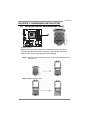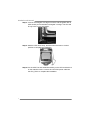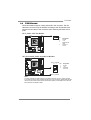
1
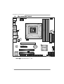
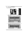
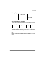
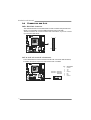
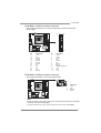
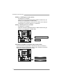
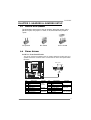
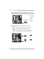
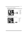
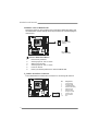
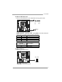
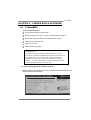
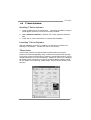
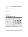
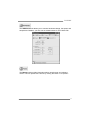
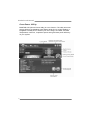
TH55XE Set up M anu al FCC Information and Copyright This equipment has been tested and found to comply with the limits of a Class B digital device, pursuant to Part 15 of the FCC Rules. These limits are designed to provide reasonable protection against harmful interference in a residential installation. This equipment generates, uses, and can radiate radio frequency energy and, if not installed and used in accordance with the instructions, may cause harmful interference to radio communications. There is no guarantee that interference will not occur in a particular installation. The vendor makes no representations or warranties with respect to the contents here and specially disclaims any implied warranties of merchantability or fitness for any purpose. Further the vendor reserves the right to revise this publication and to make changes to the contents here without obligation to notify any party beforehand. Duplication of this publication, in part or in whole, is not allowed without first obtaining the vendor’s approval in writing. The content of this user’s manual is subject to be changed without notice and we will not be responsible for any mistakes found in this user’s manual. All the brand and product names are trademarks of their respective companies. Table of Contents Chapter 1: Introduction ........................................ 1 1.1 1.2 1.3 1.4 1.5 Before You Start......................................................................................... 1 Package Checklist ..................................................................................... 1 Motherboard Features.............................................................................. 2 Rear Panel Connectors.............................................................................. 2 Motherboard Layout................................................................................. 4 Chapter 2: Hardware Installation .......................... 5 2.1 2.2 2.3 2.4 Installing Central Processing Unit (CPU) ............................................... 5 FAN Headers.............................................................................................. 7 Installing System Memory ........................................................................ 8 Connectors and Slots................................................................................ 10 Chapter 3: Headers & Jumpers Setup .................. 13 3.1 3.2 How to Setup Jumpers............................................................................. 13 Detail Settings .......................................................................................... 13 Chapter 4: T-Series BIOS & Software................... 19 4.1 4.2 T-Series BIOS............................................................................................. 19 T-Series Software...................................................................................... 27 Chapter 5: Useful Help ........................................ 36 5.1 5.2 5.3 5.4 Driver Installation Note.......................................................................... 37 Extra Information.................................................................................... 38 AMI BIOS Beep Code ............................................................................... 39 Troubleshooting ....................................................................................... 40 Appendix: SPEC In Other Languages ................... 41 German.................................................................................................................. 42 French .................................................................................................................... 44 Italian..................................................................................................................... 46 Spanish ................................................................................................................... 48 Portuguese ............................................................................................................ 50 Polish...................................................................................................................... 52 Russian ................................................................................................................... 54 Arabic..................................................................................................................... 56 Japanese ................................................................................................................ 58 TH5 5 X E CHAPTER 1: INTRODUCTION 1.1 BEFORE YOU START Thank you for choosing our product. Before you start installing the motherboard, please make sure you follow the instructions below: 1.2 Prepare a dry and stable working environment with sufficient lighting. Always disconnect the computer from power outlet before operation. Before you take the motherboard out from anti-static bag, ground yourself properly by touching any safely grounded appliance, or use grounded wrist strap to remove the static charge. Avoid touching the components on motherboard or the rear side of the board unless necessary. Hold the board on the edge, do not try to bend or flex the board. Do not leave any unfastened small parts inside the case after installation. Loose parts will cause short circuits which may damage the equipment. Keep the computer from dangerous area, such as heat source, humid air and water. The operating temperatures of the computer should be 0 to 45 degrees Celsius. PACKAGE CHECKLIST HDD Cable X 1 (optional) Serial ATA Cable X 3 Rear I/O Panel for ATX Case X 1 User’s Manual X 1 Fully Setup Driver CD X 1 FDD Cable X 1 (optional) USB 2.0 Cable X1 (optional) Serial ATA Power Cable X 1 (optional) Note: The package contents may be different due to area or your motherboard version. 1 Motherboard Manual 1.3 MOTHERBOARD FEATURES SPEC CPU Chipset Super I/O Supports Execute Disable Bit / Enhanced Intel Socket 1156 Intel Core i7 / i5 / i3/ Pentium processor Memory 64 Technology / Virtualization Technology Intel H55 IT8721 Environment Control initiatives, Provides the most commonly used legacy Hardware Monitor Controller Super I/O functionality. Fan Speed Controller Low Pin Count Interface ITE's "Smart Guardian" function DDR3 DIMM Slots x 4 Dual Channel Mode DDR3 memory module Main Max Memory Capacity 16GB Supports DDR3 800 / 1066 / 1333 Memory Each DIMM supports 512MB/ Supports DDR3 1600 (OC) / 2000 (OC) 1GB/2GB/4GB DDR3 Registered DIMM and ECC DIMM is not supported IDE JMB368 SATA 2 Integrated Serial ATA Controller LAN Realtek RTL 8111DL Sound Ultra DMA 33 / 66 / 100 / 133 Bus Master Mode supports PIO Mode 0~4 Data transfer rates up to 3.0 Gb/s. SATA Version 2.0 specification compliant 10 / 100 Mb/s / 1Gb/s auto negotiation Half / Full duplex capability 7.1 channels audio out ALC888 High Definition Audio Codec IEEE 1394 Slots On Board LSI FW322 1394a PCI slot x2 Supports PCI expansion cards PCI Express Gen2 x 16 slot x1 Supports PCI-E Gen2 x16 expansion cards PCI Express Gen2 x 4 slot x1 Supports PCI-E Gen2 x4 expansion cards IDE Connector x1 Each connector supports 2 IDE device SATA Connector x5 Each connector supports 1 SATA devices Front Panel Connector x1 Supports front panel facilities Front Audio Connector x1 Supports front panel audio function CPU Fan Header x1 CPU Fan power supply (with Smart Fan function) System Fan Header x2 System Fan Power supply Clear CMOS Header x1 Restore CMOS data to factory default x3 Each connector supports 2 front panel USB ports Connectors USB Connector Printer Port Connector 2 SpeedStep® / Intel Architecture-64 / Extended x1 Each connector supports 1 Printer port Serial Port Connector x1 Connects to RS-232 Port IEEE 1394 Connector x1 Connects to IEEE 1394 device Power Connector (24pin) x1 Connects to Power supply Power Connector (8pin) x1 Connects to Power supply TH5 5 X E SPEC Back Panel I/O Board Size PS/2 Keyboard x1 Connects to PS/2 Keyboard PS/2 Mouse x1 Connects to PS/2 Mouse S/PDIF Out x1 Provides digital audio out function HDMI Port x1 Connects to HDMI cable VGA Port x1 Connect to D-SUB monitor DVI-D Port x1 Connect to DVI monitor 1394 Port x1 Connects to IEEE 1394 device eSATA Port x1 Connect to SATA devices LAN port x1 Connect to RJ-45 ethernet cable USB Port x4 Connect to USB devices Audio Jack x6 Provide Audio-In/Out and Mic. connection 244 (W) x 244 (L) mm uATX Biostar reserves the right to add or remove support OS Support Windows XP / Vista / 7 1.4 for any OS with or without notice REAR PANEL CONNECTORS PS/2 Mouse USBX2 LAN IEEE 1394 eSATA USBX2 DVI-D PS/2 S/PDIF Keyboard Out HDMI VGA Center Line In Rear Line Out Side Mic In NOTE: HDMI / DVI-D / VGA Output require an Intel Core family processor with Intel Graphics Technology. NOTE: Maximum resolution: HDMI: 1920 x 1200 @60Hz DVI: 1920 x 1200 @60Hz VGA: 2048 x 1536 @75Hz NOTE: This motherboard supports Multiple VGA output, so any two of the onboard VGA, DVI-D, and HDMI ports can be connected at the same time. Please note that HDMI + DVI-D dual output only works under OS and that HDMI is not supported under DOS and BIOS setup. Display Devices VGA + HDMI Enabled O VGA + DVI-D HDMI + DVI-D O O 3 Motherboard Manual MOTHERBOARD LAYOUT KBMS1 ATXPWR2 VAXG _LED1 PH1 PH2 PH3 PH4 VTT_LED1 VTT_LED2 1.5 CP U_FAN 1 SPD IF1 HDMI1 Socket 1156 D DR 3_B1 D DR 3_B2 D DR 3_A1 D DR 3_A2 D VI VG A CPU1 JUSBV1 JCMO S1 IDE USB_1394_ ESATA1 IDE1 R J45U SB1 LAN AU DIO1 SY S_FA N2 F_AU DIO1 ATXP W R1 PEX16_1 CODEC BAT1 PEX4_1 H55 BIOS SW_RST1 PCI1 SW_PWR1 LED_D2 LED_D1 C IR1 Super I/O PCI2 SY S_FA N1 F_USB 3 F_US B2 F_U SB 1 SATA2 SATA1 SATA4 SATA3 JUS BV 2 J_P RIN T1 J_COM1 F_1394 Note: ■ represents the 1st pin. 4 PA NE L1 SATA5 TH5 5 X E CHAPTER 2: HARDWARE INSTALLATION 2.1 INSTALLING CENTRAL PROCESSING UNIT (CPU) Special Notice: Remove Pin Cap before installation, and make good preservation for future use. When the CPU is removed, cover the Pin Cap on the empty socket to ensure pin legs won’t be damaged. Step 1: Pull the socket locking lever out from the socket and then raise the lever up. Step 2: Remove the Pin Cap. 5 Motherboard Manual Step 3: Look for the triangular cut edge on socket, and the golden dot on CPU should point forwards this triangular cut edge. The CPU will fit only in the correct orientation. Step 4: Hold the CPU down firmly, and then lower the lever to locked position to complete the installation. Step 5: Put the CPU Fan and heatsink assembly on the CPU and buckle it on the retention frame. Connect the CPU FAN power cable into the CPU_FAN1 to complete the installation. 6 TH5 5 X E 2.2 FAN HEADERS These fan headers support cooling-fans built in the computer. The fan cable and connector may be different according to the fan manufacturer. Connect the fan cable to the connector while matching the black wire to pin#1. CPU_FAN1: CPU Fan Header 4 1 Pin 1 2 3 4 Assignment Ground +12V FAN RPM rate sense Smart Fan Control SYS_FAN1/SYS_FAN2: System Fan Headers SYS_FAN2 3 1 1 3 Pin 1 2 3 Assignment Ground +12V FAN RPM rate sense SYS_FAN1 Note: The SYS_FAN1/SYS_FAN2 support 3-pin head connectors; the CPU_FAN1 supports 4-pin head connector. When connecting with wires onto connectors, please note that the red wire is the positive and should be connected to pin#2, and the black wire is Ground and should be connected to GND. 7 Motherboard Manual 2.3 INSTALLING SYSTEM MEMORY 8 DDR3_B2 DDR3_B1 DDR3_A2 DDR3_A1 A. Memory Modules 1. Unlock a DIMM slot by pressing the retaining clips outward. Align a DIMM on the slot such that the notch on the DIMM matches the break on the Slot. 2. Insert the DIMM vertically and firmly into the slot until the retaining chip snap back in place and the DIMM is properly seated. TH5 5 X E B. Memory Capacity DIMM Socket Location DDR3 Module DDR3_A1 512MB/1GB/2GB/4GB DDR3_A2 512MB/1GB/2GB/4GB DDR3_B1 512MB/1GB/2GB/4GB DDR3_B2 512MB/1GB/2GB/4GB Total Memory Size Max is 16GB. C. Dual Channel Memory Installation Please refer to the following requirements to activate Dual Channel function: Install memory module of the same density in pairs, shown in the table. Dual Channel Status DDR3_A2 DDR3_A1 DDR3_B2 DDR3_B1 Enabled X O X O Enabled O O O O (O means memory installed, X means memory not installed.) The DRAM bus width of the memory module must be the same (x8 or x16) Note: Memory module must be installed in DDR3-A1 or DDR3-B1 to boot the system. 9 Motherboard Manual 2.4 CONNECTORS AND SLOTS IDE1: Hard Disk Connector The motherboard has a 32-bit Enhanced PCI IDE Controller that provides PIO Mode 0~4, Bus Master, and Ultra DMA 33/66/100/133 functionality. The IDE connector can connect a master and a slave drive, so you can connect up to two hard disk drives. 1 2 39 40 SATA1~SATA5: Serial ATA Connectors The motherboard has a PCI to SATA Controller with 5 channels SATA interface, it satisfies the SATA 2.0 spec and with transfer rate of 3.0Gb/s. SATA2 SATA1 SATA4 SATA3 SATA5 1 10 4 7 Pin 1 2 3 4 5 6 7 Assignment Ground TX+ TXGround RXRX+ Ground TH5 5 X E ATXPWR1: ATX Power Source Connector This connector allows user to connect 24-pin power connector on the ATX power supply. Pin 13 14 15 16 17 18 19 20 21 22 23 24 Assignment +3.3V -12V Ground PS_ON Ground Ground Ground NC +5V +5V +5V Ground Pin 1 2 3 4 5 6 7 8 9 10 11 12 12 24 1 13 Assignment +3.3V +3.3V Ground +5V Ground +5V Ground PW_OK Standby Voltage+5V +12V +12V +3.3V ATXPWR2: ATX Power Source Connector This connector provides +12V to CPU power circuit. 4 1 5 8 Pin 1 2 3 4 Assignment +12V +12V Ground Ground Note: Before you power on the system, please make sure that both ATXPWR1 and ATXPWR2 connectors have been well plugged-in. If the CPU power plug is 4-pin, please plug it into Pin 1-2-5-6 of ATXPWR2. 11 Motherboard Manual PEX16_1: PCI-Express Gen2 x16 Slot - PCI-Express 2.0 compliant. Maximum theoretical realized bandwidth of 8GB/s simultaneously per direction, for an aggregate of 16GB/s totally. PCI-Express Gen2 supports a raw bit-rate of 5.0Gb/s on the data pins. 2X bandwidth over the PCI-Express 1.1 architecture. PEX4_1: PCI-Express Gen 2 x4 Slot - PCI-Express 2.0 compliant. Maximum theoretical realized bandwidth of 1GB/s simultaneously per direction, for an aggregate of 2GB/s totally. PEX16_1 PEX4_ 1 PCI1/PCI2: Peripheral Component Interconnect Slots This motherboard is equipped with 2 standard PCI slots. PCI stands for Peripheral Component Interconnect, and it is a bus standard for expansion cards. This PCI slot is designated as 32 bits. PCI 1 PCI2 12 TH5 5 X E CHAPTER 3: HEADERS & JUMPERS SETUP 3.1 HOW TO SETUP JUMPERS The illustration shows how to set up jumpers. When the jumper cap is placed on pins, the jumper is “close”, if not, that means the jumper is “open”. Pin opened 3.2 Pin closed Pin1-2 closed DETAIL SETTINGS PANEL1: Front Panel Header This 16-pin connector includes Power-on, Reset, HDD LED, Power LED, and speaker connection. It allows user to connect the PC case’s front panel switch functions. POW_LED On/Off + + - 9 1 16 8 + SPK RST HLED Pin 1 2 3 4 5 6 7 8 Assignment +5V N/A N/A Speaker HDD LED (+) HDD LED (-) Ground Reset control Function Speaker Connector Hard drive LED Reset button Pin 9 10 11 12 13 14 15 16 Assignment N/A N/A N/A Power LED (+) Power LED (+) Power LED (-) Power button Ground Function N/A N/A Power LED Power-on button 13 Motherboard Manual F_USB1/F_USB2/F_USB3: Headers for USB 2.0 Ports at Front Panel These headers allow user to connect additional USB cable on the PC front panel, and also can be connected with internal USB devices, like USB card reader. F_ USB3 F_ USB1 F_USB2 2 10 1 9 Pin 1 2 3 4 5 6 7 8 9 10 Assignment +5V (fused) +5V (fused) USBUSBUSB+ USB+ Ground Ground Key NC JUSBV1/JUSBV2: Power Source Headers for USB Ports Pin 1-2 Close: JUSBV1: +5V for USB ports at USB_1394_ESATA1/RJ45USB1. JUSBV2: +5V for USB ports at F_USB1/F_USB2/F_USB3. Pin 2-3 Close: JUSBV1: +5V STB for USB ports at USB_1394_ESATA1/RJ45USB1. JUSBV2: +5V STB for USB ports at F_USB1/F_USB2/F_USB3. 1 3 1 3 Pin 1-2 close JUSBV1 3 1 1 Pin 2-3 close JUSBV2 14 3 TH5 5 X E F_AUDIO1: Front Panel Audio Header This header allows user to connect the front audio output cable with the PC front panel. This header allows only HD audio front panel connector; AC’97 connector is not acceptable. 1 2 9 10 Pin 1 2 3 4 5 6 7 8 9 10 Assignment Mic Left in Ground Mic Right in GPIO Right line in Jack Sense Front Sense Key Left line in Jack Sense F_1394: IEEE 1394 Header This header allows user to connect IEEE 1394 device. 2 10 1 9 Pin 1 2 3 4 5 6 7 8 9 10 Assignment TPA1+ TPA1GND GND TPB1+ TPB1VCC VCC N/A KEY 15 Motherboard Manual JCMOS1: Clear CMOS Header Placing the jumper on pin2-3 allows user to restore the BIOS safe setting and the CMOS data. Please carefully follow the procedures to avoid damaging the motherboard. 1 3 Pin 1-2 Close: Normal Operation (default). 1 3 1 3 Pin 2-3 Close: Clear CMOS data. ※ Clear CMOS Procedures: 1. 2. 3. 4. 5. 6. Remove AC power line. Set the jumper to “Pin 2-3 close”. Wait for five seconds. Set the jumper to “Pin 1-2 close”. Power on the AC. Reset your desired password or clear the CMOS data. J_COM1: Serial Port Connector The motherboard has a Serial Port Connector for connecting RS-232 Port. 16 2 10 1 9 Pin Assignment 1 2 3 4 5 6 7 8 9 10 Carrier detect Received data Transmitted data Data terminal ready Signal ground Data set ready Request to send Clear to send Ring indicator NC TH5 5 X E On-Board LED Indicators VAXG_LED1 PH1 PH2 PH3 PH4 VTT_LED1 VTT_LED2 There are 9 LED indicators on the motherboard showing system status. LED_D2 LED_D1 LED_D1 & LED_D2: Debug Indicators VAXG_LED1/PH1 ~ PH4 / VTT_LED1 ~ VTT_LED2: Power Status Indicators Please refer to the tables below for specific messages: LED_D1 ON ON OFF OFF LED_D2 ON OFF ON OFF VAXG_LED1 PH1~PH4 VTT_LED1~VTT_LED2 ON OFF Message Normal Memory Error VGA Error Abnormal: CPU / Chipset error. Phase Indicator Phase Active Phase Inactive On-Board Buttons There are 2 on-board buttons. SW_RST1 SW_PWR1 SW_RST1: Reset button. SW_PWR1: Power Switch button. 17 Motherboard Manual J_PRINT1: Printer Port Connector This header allows you to connector printer on the PC. 18 Assignment 2 26 1 25 Pin 1 2 3 4 5 -Strobe -ALF Data 0 -Error Data 1 Pin 14 15 16 17 18 Ground Data 6 Ground Data 7 Ground Assignment 6 7 8 9 10 11 12 13 -Init Data 2 -Scltin Data 3 Ground Data 4 Ground Data 5 19 20 21 22 23 24 25 26 -ACK Ground Busy Ground PE Ground SCLT Key TH5 5 X E CHAPTER 4: T-SERIES BIOS & SOFTWARE 4.1 T-SERIES BIOS T-Series BIOS Features Overclocking Navigator Engine (O.N.E.) Memory Integration Test (M.I.T., under Overclock Navigator Engine) BIO-Flasher: Update BIOS file from USB Flash Drive or FDD Self Recovery System (S.R.S) Smart Fan Function CMOS Reloading Program !! WARNING !! For better system performance, the BIOS firmware is being continuously updated. The BIOS information described below in this manual is for your reference only and the actual BIOS information and settings on board may be different from this manual. For further information of setting up the BIOS, please refer to the BIOS Manual in the Setup CD. A. Overclocking Navigator Engine (O.N.E.) ONE provides two powerful overclocking engines: MOS and AOS for both Elite and Casual overclockers. Main Advanced PCIPnP BIOS SETUP UTILITY Boot Chipset Over-Clocking Navigator Setting Notice:Please Clear CMOS if system no display after overclocking. Over-Clocking Navigator [Normal] =========== Automate OverClock System =========== Auto OverClock System [V6-Tech Engine] ============ Manual OverClock System ============ Current CPU Frequency : Current Memory Frequency : Current UNCORE Frequency : Current QPI Frequency : Over Clock Retry Count [1] Intel(R) SpeedStep(tm) tech [Enabled] CPU Ratio Setting [ x25.0] CPU Frequency Setting [133] QPI Frequency [Auto] DRAM Frequency [Auto] > DRAM Timing Configuration > Clock Gen Configuration > Voltage Control O.N.E Exit Options Normal Automate OverClock Manual OverClock Select Screen Select Item EnterGo to Sub Screen F1 General Help F10 Save and Exit ESC Exit vxx.xx (C)Copyright 1985-200x, American Megatrends, Inc. 19 Motherboard Manual Manual Overclock System (M.O.S.) MOS is designed for experienced overclock users. It allows users to customize personal overclock settings. Main Advanced PCIPnP BIOS SETUP UTILITY Boot Chipset O.N.E Exit Over-Clocking Navigator Setting Options Notice:Please Clear CMOS if system no display after overclocking. Over-Clocking Navigator [Normal] =========== Automate OverClock System =========== Auto OverClock System [V6-Tech Engine] ============ Manual OverClock System ============ Current CPU Frequency : Options Current Memory Frequency : Normal Current UNCORE Frequency : Automate OverClock Current QPI Frequency : Manual Over Clock Retry Count [1] OverClock Intel(R) SpeedStep(tm) tech [Enabled] CPU Ratio Setting [ x25.0] CPU Frequency Setting [133] QPI Frequency [Auto] DRAM Frequency [Auto] > DRAM Timing Configuration > Clock Gen Configuration > Voltage Control Normal Automate OverClock Manual OverClock Select Screen Select Item EnterGo to Sub Screen F1 General Help F10 Save and Exit ESC Exit vxx.xx (C)Copyright 1985-200x, American Megatrends, Inc. ↓ Main Advanced PCIPnP BIOS SETUP UTILITY Boot Chipset O.N.E Exit Over-Clocking Navigator Setting Notice:Please Clear CMOS if system no display after overclocking. Over-Clocking Navigator [Manual OverClock] =========== Automate OverClock System =========== Auto OverClock System [V6-Tech Engine] ============ Manual OverClock System ============ Current CPU Frequency : Current Memory Frequency : Current UNCORE Frequency : Current QPI Frequency : Over Clock Retry Count [1] Intel(R) SpeedStep(tm) tech [Enabled] CPU Ratio Setting [ x25.0] CPU Frequency Setting [133] QPI Frequency [Auto] DRAM Frequency [Auto] > DRAM Timing Configuration > Clock Gen Configuration > Voltage Control Options Normal Automate OverClock Manual OverClock Select Screen Select Item EnterGo to Sub Screen F1 General Help F10 Save and Exit ESC Exit vxx.xx (C)Copyright 1985-200x, American Megatrends, Inc. Over Clock Retry Count This item allows you to set the overclock fail retry times. Intel(R) SpeedStep(tm) Tech This item allows you to enable SpeedStep technology for better power saving. SpeedStep is a technology built into some Intel processors that allows the clock speed of the processor to be dynamically changed by software. CPU Ratio Setting This item allows you to set the CPU ratio frequency. This item is adjustable only when SpeedStep Tech is set to Disabled CPU Frequency Setting This item allows you to select the CPU Frequency. QPI Frequency This item allows you to select the QPI Frequency. 20 TH5 5 X E DRAM Frequency To get better system performance, sometimes downgrading the memory frequency is necessary when CPU frequency is adjusted over the upper limit. DRAM Timing Configuration Enter this item for more advanced DRAM timing settings. Clock Gen Configuration Enter this item for more advanced Clock Gen settings. Voltage Control Enter this item for more advanced voltage settings. Intel PPM Configuration Enter this item for more advanced Intel PPM settings. BIOSTAR Me mory Insight Enter this item for more advanced memory SPD information. G.P.U Phase Control Enter this function for more power saving settings. NOTE Overclock is an optional process, but not a “must-do” process; it is not recommended for inexperienced users. Therefore, we will not be responsible for any hardware damage which may be caused by overclocking. We also would not guarantee any overclocking performance. Automatic Overclock System (A.O.S.) For beginners in overclock field, BET had developed an easy, fast, and powerful feature to increase the system performance, named A.O.S. Based on many tests and experiments, A.O.S. provides 3 ideal overclock configurations that are able to raise the system performance in a single step. Main Advanced PCIPnP BIOS SETUP UTILITY Boot Chipset Over-Clocking Navigator Setting Notice:Please Clear CMOS if system no display after overclocking. Over-Clocking Navigator [Normal] =========== Automate OverClock System =========== Auto OverClock System [V6-Tech Engine] ============ Manual OverClock System ============ Current CPU Frequency : Options Current Memory Frequency : Normal Current UNCORE Frequency : Automate OverClock Current QPI Frequency : Manual Over Clock Retry Count [1] OverClock Intel(R) SpeedStep(tm) tech [Enabled] CPU Ratio Setting [ x25.0] CPU Frequency Setting [133] QPI Frequency [Auto] DRAM Frequency [Auto] > DRAM Timing Configuration > Clock Gen Configuration > Voltage Control O.N.E Exit Options Normal Automate OverClock Manual OverClock Select Screen Select Item EnterGo to Sub Screen F1 General Help F10 Save and Exit ESC Exit vxx.xx (C)Copyright 1985-200x, American Megatrends, Inc. 21 Motherboard Manual V6 Tech Engine This engine will make a good over-clock performance. Main Advanced PCIPnP BIOS SETUP UTILITY Boot Chipset O.N.E Exit Over-Clocking Navigator Setting Options Notice:Please Clear CMOS if system no display after overclocking. Over-Clocking Navigator [Automate OverClock] =========== Automate OverClock System =========== Auto OverClock System [V6-Tech Engine] ============ Manual OverClock System ============ Current CPU Frequency : Current Memory Frequency : Current UNCORE Frequency : Current QPI Frequency : Over Clock Retry Count [1] Intel(R) SpeedStep(tm) tech [Enabled] CPU Ratio Setting [ x25.0] CPU Frequency Setting [133] QPI Frequency [Auto] DRAM Frequency [Auto] > DRAM Timing Configuration > Clock Gen Configuration > Voltage Control V6-Tech Engine V8-Tech Engine V12-Tech Engine Select Screen Select Item EnterGo to Sub Screen F1 General Help F10 Save and Exit ESC Exit vxx.xx (C)Copyright 1985-200x, American Megatrends, Inc. V8 Tech Engine This engine will make a better over-clock performance. Main Advanced PCIPnP BIOS SETUP UTILITY Boot Chipset O.N.E Exit Over-Clocking Navigator Setting Options Notice:Please Clear CMOS if system no display after overclocking. Over-Clocking Navigator [Automate OverClock] =========== Automate OverClock System =========== Auto OverClock System [V8-Tech Engine] ============ Manual OverClock System ============ Current CPU Frequency : Current Memory Frequency : Current UNCORE Frequency : Current QPI Frequency : Over Clock Retry Count [1] Intel(R) SpeedStep(tm) tech [Enabled] CPU Ratio Setting [ x25.0] CPU Frequency Setting [133] QPI Frequency [Auto] DRAM Frequency [Auto] > DRAM Timing Configuration > Clock Gen Configuration > Voltage Control V6-Tech Engine V8-Tech Engine V12-Tech Engine Select Screen Select Item EnterGo to Sub Screen F1 General Help F10 Save and Exit ESC Exit vxx.xx (C)Copyright 1985-200x, American Megatrends, Inc. V12 Tech Engine This engine will make a best over-clock performance. Main Advanced PCIPnP BIOS SETUP UTILITY Boot Chipset O.N.E Over-Clocking Navigator Setting Notice:Please Clear CMOS if system no display after overclocking. Over-Clocking Navigator [Automate OverClock] =========== Automate OverClock System =========== Auto OverClock System [V12-Tech Engine] ============ Manual OverClock System ============ Current CPU Frequency : Current Memory Frequency : Current UNCORE Frequency : Current QPI Frequency : Over Clock Retry Count [1] Intel(R) SpeedStep(tm) tech [Enabled] CPU Ratio Setting [ x25.0] CPU Frequency Setting [133] QPI Frequency [Auto] DRAM Frequency [Auto] > DRAM Timing Configuration > Clock Gen Configuration > Voltage Control Exit Options V6-Tech Engine V8-Tech Engine V12-Tech Engine Select Screen Select Item EnterGo to Sub Screen F1 General Help F10 Save and Exit ESC Exit vxx.xx (C)Copyright 1985-200x, American Megatrends, Inc. 22 TH5 5 X E Notices: Not all types of Intel CPU perform above overclock setting ideally; the difference will be based on the selected CPU model. B. Memory Integration Test (M.I.T.) This function is under “Overclocking Navigator Engine” item. MIT allows users to test memory compatibilities, and no extra devices or software are needed. Step 1 The default setting under this item is “HotKey F11”; the condition parameter should be changed to “Enable” to proceed this test. Main Advanced PCIPnP BIOS SETUP UTILITY Boot Chipset Auto OverClock System [V6-Tech Engine] ============ Manual OverClock System ============ Current CPU Frequency : Current Memory Frequency : Current UNCORE Frequency : Currnet QPI Frequency : Over Clock Retry Count [1] Intel(R) SpeedStep(tm) tech [Enabled] CPU Ratio Setting [ x25.0] CPU Frequency Setting [133] QPI Frequency [Auto] DRAM Frequency [Auto] > DRAM Timing Configuration > Clock Gen Configuration > Voltage Control > Intel PPM Configuration > BIOSTAR Memory Insight > G.P.U Phase Control Integrated Memory Test [HotKey F11] O.N.E Exit Options HotKey F11 Disabled Enabled Select Screen Select Item EnterGo to Sub Screen F1 General Help F10 Save and Exit ESC Exit vxx.xx (C)Copyright 1985-200x, American Megatrends, Inc. ↓ Main Advanced PCIPnP BIOS SETUP UTILITY Boot Chipset Auto OverClock System [V6-Tech Engine] ============ Manual OverClock System ============ Current CPU Frequency : Current Memory Frequency : Current UNCORE Frequency : Currnet QPI Frequency : Over Clock Retry Count [1] Intel(R) SpeedStep(tm) tech [Enabled] CPU Ratio Setting [ x25.0] CPU Frequency Setting [133] QPI Frequency [Auto] DRAM Frequency [Auto] > DRAM Timing Configuration > Clock Gen Configuration > Voltage Control > Intel PPM Configuration > BIOSTAR Memory Insight > G.P.U Phase Control Integrated Memory Test [Enabled] O.N.E Exit Options HotKey F11 Disabled Enabled Select Screen Select Item EnterGo to Sub Screen F1 General Help F10 Save and Exit ESC Exit vxx.xx (C)Copyright 1985-200x, American Megatrends, Inc. Step 2 Save and Exit from CMOS setup and reboot the system to activate this test. Run this test for 5 minutes (minimum) to ensure the memory stability. Step 3 When the process is done, change the setting back from “Enable” to “Disable” to complete the test. 23 Motherboard Manual C. BIO-Flasher BIO-Flasher is a BIOS flashing utility providing you an easy and simple way to update your BIOS via USB pen drive or floppy disk. The BIO-Flasher is built in the BIOS chip. To enter the utility, press <F12> during the Power-On Self Tests (POST) procedure while booting up. Updating BIOS with BIO-Flasher 1. Go to the website to download the latest BIOS file for the motherboard. 2. Then, save the BIOS file into a USB pen drive or a floppy disk. 3. Insert the USB pen drive or the floppy disk that contains the BIOS file to the USB port or the floppy disk drive. 4. Power on or reset the computer and then press <F12> during the POST process. A select dialog as the picture on the right appears. Select the device contains the BIOS file and press <Enter> to enter the utility. 5. The utility will show the BIOS files and their respective information. Select the proper BIOS file and press <Enter> then <Y> to perform the BIOS update process. 6. After the update process, the utility will ask you to reboot the system. Press <Y> to proceed. BIOS update completes. z z 24 This utility only allows storage device with FAT32/16 format and single partition. Shutting down or resetting the system while updating the BIOS will lead to system boot failure. TH5 5 X E D. Self Recovery System (S.R.S.) This function can’t be seen under BIOS setup; and is always on whenever the system starts up. However, it can prevent system hang-up due to inappropriate overclock actions. When the system hangs up, S.R.S. will automatically log in the default BIOS setting, and all overclock settings will be re-configured. E. Smart Fan Function Smart Fan Function is under “Smart Fan Configuration” in “Advanced Menu”. This is a brilliant feature to control CPU/System Temperature vs. Fan speed. When enabling Smart Fan function, Fan speed is controlled automatically by CPU/System temperature. This function will protect CPU/System from overheat problem and maintain the system temperature at a safe level. Main Advanced PCIPnP BIOS SETUP UTILITY Boot Chipset Advanced Settings Exit O.N.E Configure CPU. WARNING: Setting wrong values in below sections may cause system to malfunction. > > > > > > > > > > > CPU Configuration SuperIO Configuration Hardware Health Configuration Smart Fan Configuration ACPI Configuration Onboard PCI/PCI-E Devices Configuration Intel VT-d Configuration MPS Configuration PCI Express Configuration Smbios Configuration USB Configuration Select Screen Select Item EnterGo to Sub Screen F1 General Help F10 Save and Exit ESC Exit vxx.xx (C)Copyright 1985-200x, American Megatrends, Inc. ↓ Advanced BIOS SETUP UTILITY Smart Fan Configuration CPU Smart Fan Smart Fan Calibration Control Mode o Fan Ctrl OFF( C) o Fan Ctrl On( C) Fan Ctrl Start value Fan Ctrl Sensitive [Disabled] When you choice [Auto] please run the calibration to define the Fan parameters for Smart Fan control +F1 F10 ESC Select Screen Select Item Change Option General Help Save and Exit Exit vxx.xx (C)Copyright 1985-200x, American Megatrends, Inc. 25 Motherboard Manual Smart Fan Calibration Choose this item and then the BIOS will automatically test and detect the CPU/System fan functions and show CPU/System fan speed. Control Mode This item provides several operation modes of the fan. Fan Ctrl OFF(℃) If the CPU/System temperature is lower than the set value, the CPU/ System fan will turn off. The range is from 0~127, with an interval of 1. Fan Ctrl On(℃) The CPU/System fan starts to work when CPU/System temperature arrives to this set value. The range is from 0~127, with an interval of 1. Fan Ctrl Start Value When CPU/System temperature arrives to the set value, the CPU/System fan will work under Smart Fan Function mode. The range is from 0~127, with an interval of 1. Fan Ctrl Sensitive Increasing the value of slope PWM will raise the speed of CPU/System fan. The range is from 1~127, with an interval of 1. F. CMOS Reloading Program It allows users to save different CMOS settings into BIOS-ROM. Users are able to reload any saved CMOS setting for customizing system configurations. Moreover, users are able to save an ideal overclock setting during overclock operation. There are 10 sets of record addresses in total, and users are able to name the CMOS data according to personal preference. Main Advanced PCIPnP BIOS SETUP UTILITY Boot Chipset O.N.E Exit Exit Options Save Changes and Exit Discard Changes and Exit Discard Changes Load Optimal Defaults Security Settings CMOS Backup Func CMOS Data Reload CMOS Data Save > Security CMOS Backup Function Select Screen Select Item Enter Go to Sub Screen F1 General Help F10 Save and Exit ESC Exit vxx.xx (C)Copyright 1985-200x, American Megatrends, Inc. 26 TH5 5 X E 4.2 T-SERIES SOFTWARE Installing T-Series Software 1. Insert the Setup CD to the optical drive. The drivers installation program would appear if the Auto-run function has been enabled. 2. Select Software Installation, and then click on the respective software title. 3. Follow the on-screen instructions to complete the installation. Launching T-Series Software After the installation process is completed, you will see the software icon showing on the desktop. Double-click the icon to launch it. TOverclocker TOverclocker presents a simple Windows-based system performance enhancement and manageability utility. It features several powerful and easy to use tools such as Overclocking for enhancing system performance, also for special enhancement on CPU and Memory. Smart-Fan control is for managing fan speed control of both CPU cooling fan and North-Bridge Chipset cooling fan. PC health is for monitoring system status. And pre-set OC modes are for easy OC. 27 Motherboard Manual The CPU tab provides information on the CPU and motherboard. The Memory tab provides information on the memory module(s). You can select memory module on a specific slot to see its information. The OC Tweaker tab allows you to change system clock settings and voltages settings. It also provides six pre-set modes for you: 28 TH5 5 X E The HW Monitor tab allows you to monitor hardware voltage, fan speed, and temperature. Besides, you also can set related values for CPU Smart Fan. The Memory tab provides information about manufacturer and software version. You can update new version by clicking the button “Live Update.” 29 Motherboard Manual Green Power Utility BIOSTAR G.P.U (Green Power Utility) is a new function. The utility enhances energy efficiency by disabling extra phases while CPU is on light loading. It integrates a friendly GUI to monitor your CPU Usage, CPU Watt, and CPU Temperature; moreover, it optimizes power saving and best power efficiency on your system. 30 TH5 5 X E G.P.U Mode Setting This utility provides five modes, upon your requirements, to improve system performance or to save power consumption. Note: Even if the modes saving more power consumption are chosen, the system still can keep excellent performance. Auto Phase Mode System switches the mode automatically according to current system loading condition. Performance Mode This is the mode saving power consumption most. Least energy will be used in the system. Typical Mode Compared with that in Performance Mode, energy consumption in this mode is a little bit more. Medium Mode This is the standard system power saving mode. Maxi-Energy Mode This is the best system performance mode. 31 Motherboard Manual eHot-Line (Optional) eHot-Line is a convenient utility that helps you to contact with our Tech-Support system. This utility will collect the system information which is useful for analyzing the problem you may have encountered, and then send these information to our tech-support department to help you fix the problem. Before you use this utility, please set Outlook Express as your default e-mail client application program. represent s import ant *information that you must provide. Without this informat ion, you may not be able to send out the mail. This block will show the information which would be collect ed in the mail. condition * Describe of your system. your area or * Select the area close to you. Provide the e-mail address that you would like to send t he copy to. the name of * Provide the memory module manufacturer. Provide the name of the power supply manufacturer and the model no. Send the mail out. Exit this dialog. Save these information to a .txt file After filling up this information, click “Send” to send the mail out. A warning dialog would appear asking for your confirmation; click “Send” to confirm or “Do Not Send” to cancel. If you want to save this information to a .txt file, click “Save As…” and then you will see a saving dialog appears asking you to enter file name. 32 TH5 5 X E Enter the file name and then click “Save”. Your system information will be saved to a .txt file. Open the saved .txt file, you will see your system information including motherboard/BIOS/CPU/video/ device/OS information. This information is also concluded in the sent mail. We will not share customer’s data with any other third parties, so please feel free to provide your system information while using eHot-Line service. If you are not using Outlook Express as your default e-mail client application, you may need to save the system information to a .txt file and send the file to our tech support with other e-mail application. Go to the following web http://www.biostar.com.tw/app/en-us/about/contact.php for getting our contact information. 33 Motherboard Manual BIOS Update BIOS Update is a convenient utility which allows you to update your motherboard BIOS under Windows system. AWARD BIOS Show current BIOS information Clear CMOS function (Only for AWARD BIOS) Save current BIOS to a .bin file Update BIOS with a BIOS file <Backup BIOS> Once click on this button, the saving dialog will show. Choose the position to save file and enter file name. (We recommend that the file name should be English/number and no longer than 7 characters.) Then click Save. 34 AMI BIOS TH5 5 X E <Update BIOS> Before doing this, please download the proper BIOS file from the website. For AWARD BIOS, update BIOS procedure should be run with Clear CMOS function, so please check on Clear CMOS first. Then click Update BIOS button, a dialog will show for asking you backup current BIOS. Click Yes for BIOS backup and refer to the Backup BIOS procedure; or click No to skip this procedure. After the BIOS Backup procedure, the open dialog will show for requesting the BIOS file which is going to be updated. Please choose the proper BIOS file for updating, then click on Open. The utility will update BIOS with the proper BIOS file, and this process may take minutes. Please do not open any other applications during this process. After the BIOS Update process, click on OK to restart the system. While the system boots up and the full screen logo shows, press key to enter BIOS setup. <Delete> In the BIOS setup, use the Load Optimized Defaults function and then Save and Exit Setup to exit BIOS setup. BIOS Update is completed. All the information and content above about the T-Series software are subject to be changed without notice. For better performance, the software is being continuously updated. The information and pictures described above are for your reference only. The actual information and settings on board may be slightly different from this manual. 35 Motherboard Manual BIOScreen Utility This utility allows you to personalize your boot logo easily. You can choose JPG or BMP as your boot logo so as to customize your computer. Please follow the following instructions to update boo logo: 1. Load Image:Choose the picture as the boot logo. 2. Transform:Transform the picture for BIOS and preview the result. 3. Update Bios:Write the picture to BIOS Memory to complete the update. 36 TH5 5 X E CHAPTER 5: USEFUL HELP 5.1 DRIVER INSTALLATION NOTE After you installed your operating system, please insert the Fully Setup Driver CD into your optical drive and install the driver for better system performance. You will see the following window after you insert the CD The setup guide will auto detect your motherboard and operating system. Note: If this window didn’t show up after you insert the Driver CD, please use file browser to locate and execute the file SETUP.EXE under your optical drive. A. Driver Installation To install the driver, please click on the Driver icon. The setup guide will list the compatible driver for your motherboard and operating system. Click on each device driver to launch the installation program. B. Software Installation To install the software, please click on the Software icon. The setup guide will list the software available for your system, click on each software title to launch the installation program. C. Manual Aside from the paperback manual, we also provide manual in the Driver CD. Click on the Manual icon to browse for available manual. Note: You will need Acrobat Reader to open the manual file. Please download the latest version of Acrobat Reader software from http://www.adobe.com/products/acrobat/readstep2.html 37 Motherboard Manual 5.2 EXTRA INFORMATION CPU Overheated If the system shutdown automatically after power on system for seconds, that means the CPU protection function has been activated. When the CPU is over heated, the motherboard will shutdown automatically to avoid a damage of the CPU, and the system may not power on again. In this case, please double check: 1. The CPU cooler surface is placed evenly with the CPU surface. 2. CPU fan is rotated normally. 3. CPU fan speed is fulfilling with the CPU speed. After confirmed, please follow steps below to relief the CPU protection function. 1. Remove the power cord from power supply for seconds. 2. Wait for seconds. 3. Plug in the power cord and boot up the system. Or you can: 1. Clear the CMOS data. (See “Close CMOS Header: JCMOS1” section) 2. Wait for seconds. 3. Power on the system again. 38 TH5 5 X E 5.3 AMI BIOS BEEP CODE Boot Block Beep Codes Number of Beeps 1 2 3 4 5 7 10 11 12 13 Description No media present. (Insert diskette in floppy drive A:) “AMIBOOT.ROM” file not found in root directory of diskette in A: Insert next diskette if multiple diskettes are used for recovery Flash Programming successful File read error No Flash EPROM detected Flash Erase error Flash Program error “AMIBOOT.ROM” file size error BIOS ROM image mismatch (file layout does not match image present in flash device) POST BIOS Beep Codes Number of Beeps 1 3 6 7 8 Description Memory refresh timer error Base memory read/write test error Keyboard controller BAT command failed General exception error (processor exception interrupt error) Display memory error (system video adapter) Troubleshooting POST BIOS Beep Codes Number of Beeps 1, 3 6, 7 8 Troubleshooting Action Reseat the memory, or replace with known good modules. Fatal error indicating a serious problem with the system. Consult your system manufacturer. Before declaring the motherboard beyond all hope, eliminate the possibility of interference by a malfunctioning add-in card. Remove all expansion cards except the video adapter. z If beep codes are generated when all other expansion cards are absent, consult your system manufacturer’s technical support. z If beep codes are not generated when all other expansion cards are absent, one of the add-in cards is causing the malfunction. Insert the cards back into the system one at a time until the problem happens again. This will reveal the malfunctioning card. If the system video adapter is an add-in card, replace or reseat the video adapter. If the video adapter is an integrated part of the system board, the board may be faulty. 39 Motherboard Manual 5.4 TROUBLESHOOTING Probable 1. There is no power in the system. Power LED does not shine; the fan of the power supply does not work 2. Indicator light on keyboard does not shine. System is inoperative. Keyboard lights are on, power indicator lights are lit, and hard drives are running. System does not boot from a hard disk drive, but can be booted from optical drive. Solution 1. 2. 3. Make sure power cable is securely plugged in. Replace cable. Contact technical support. Using even pressure on both ends of the DIMM, press down firmly until the module snaps into place. 1. Check cable running from disk to disk controller board. Make sure both ends are securely plugged in; check the drive type in the standard CMOS setup. 2. Backing up the hard drive is extremely important. All hard disks are capable of breaking down at any time. System only boots from an optical 1. Back up data and applications drive. Hard disks can be read, files. applications can be used, but system 2. Reformat the hard drive. fails to boot from a hard disk. Re-install applications and data using backup disks. Screen message shows “Invalid Review system’s equipment. Make sure Configuration” or “CMOS Failure.” correct information is in setup. System cannot boot after user installs a 1. Set master/slave jumpers second hard drive. correctly. 2. Run SETUP program and select correct drive types. Call the drive manufacturers for compatibility with other drives. 40 TH5 5 X E This page is intentionally left blank. 41 Motherboard Manual APPENDIX: SPEC IN OTHER LANGUAGES GERMAN Spezifikationen Unterstützt Execute Disable Bit / Enhanced Intel Socket 1156 CPU SpeedStep® / Intel Architecture-64 / Extended Intel Core i7 / i5 / i3/ Pentium Prozessoren Memory 64 Technology / Virtualization Technology Chipsatz Intel H55 Umgebungskontrolle, IT8721 Super E/A Bietet die häufig verwendeten alten Super Hardware-Überwachung E/A-Funktionen. Lüfterdrehzahl-Controller/-Überwachung Low Pin Count-Schnittstelle "Smart Guardian"-Funktion von ITE Dual-Kanal DDR3 Speichermodul DDR3 DIMM-Steckplätze x 4 Unterstützt DDR3 800 / 1066 / 1333 Arbeitsspeich Max. 16GB Arbeitsspeicher er Unterstützt DDR3 1600 (OC) / 2000 (OC) Jeder DIMM unterstützt 512MB/ registrierte DIMMs. ECC DIMMs werden nicht 1GB/2GB/4GB DDR3. unterstützt. Ultra DMA 33 / 66 / 100 / 133 Bus Master-Modus IDE JMB368 Unterstützt PIO-Modus 0~4, Datentransferrate bis zu 3.0Gb/s SATA Integrierter Serial ATA-Controller Konform mit der SATA-Spezifikation Version 2.0. 10 / 100 / 1000 Mb/s Auto-Negotiation LAN Realtek RTL 8111DL Halb-/ Vollduplex-Funktion HD Unterstützt High-Definition Audio Audio-Unters ALC888 7.1-Kanal-Audioausgabe tützung IEEE 1394 Steckplätze 42 LSI FW322 1394a PCI-Steckplatz x2 PCI Express Gen2 x16 Steckplatz x1 PCI Express Gen2 x 4-Steckplatz x1 TH5 5 X E Spezifikationen IDE-Anschluss x1 Jeder Anschluss unterstützt 2 IDE-Laufwerke SATA-Anschluss x5 Jeder Anschluss unterstützt 1 SATA-Laufwerk Fronttafelanschluss x1 Unterstützt die Fronttafelfunktionen Front-Audioanschluss x1 Unterstützt die Fronttafel-Audioanschlussfunktion CPU-Lüfter-Sockel x1 CPU-Lüfterstromversorgungsanschluss (mit Smart Fan-Funktion) Onboard-Ans chluss System-Lüfter-Sockel x2 "CMOS löschen"-Sockel x1 USB-Anschluss x3 System-Lüfter-Stromversorgungsanschluss Jeder Anschluss unterstützt 2 Fronttafel-USB-Anschlüsse Druckeranschluss Anschluss x1 Serieller Anschluss x1 IEEE 1394-Anschluss x1 Stromanschluss (24-polig) x1 Stromanschluss (8-polig) x1 PS/2-Tastatur x1 PS/2-Maus x1 S/PDIF Heraus x1 HDMI-Anschluss x1 VGA-Anschluss x1 DVI-D-Anschluss x1 1394-Anschluss x1 eSATA Anschluss x1 LAN-Anschluss x1 USB-Anschluss x4 Audioanschluss x6 Jeder Anschluss unterstützt 1 Druckeranschluss Rückseiten-E /A Platinengröße 244 mm (B) X 244 mm (L) uATX Biostar behält sich das Recht vor, ohne Ankündigung OS-Unterstüt zung Windows XP / Vista / 7 die Unterstützung für ein Betriebssystem hinzuzufügen oder zu entfernen. 43 Motherboard Manual FRENCH SPEC Prend en charge les technologies d'exécution de bit UC Socket 1156 de désactivation / Intel SpeedStep® optimisée/ Processeurs Intel Core i7 / i5 / i3/ Pentium d'architecture Intel 64 / de mémoire étendue 64 / de virtualisation Chipset Super E/S Intel H55 IT8721 Initiatives de contrôle environnementales, Fournit la fonctionnalité de Super E/S Moniteur de matériel patrimoniales la plus utilisée. Contrôleur /moniteur de vitesse de ventilateur Interface à faible compte de broches Fonction "Gardien intelligent" de l'ITE Module de mémoire DDR3 à mode à double voie Fentes DDR3 DIMM x 4 Prend en charge la DDR3 800 / 1066 / 1333 Mémoire Capacité mémoire maximale de 16 Go principale Chaque DIMM prend en charge des DDR3 de Prend en charge la DDR3 1600 (OC) / 2000 (OC) Les DIMM à registres et DIMM avec code correcteurs 512Mo/1Go/2Go/4Go d'erreurs ne sont pas prises en charge Mode principale de Bus Ultra DMA 33 / 66 / 100 / IDE JMB368 133 Prend en charge le mode PIO 0~4, Taux de transfert jusqu'à 3.0Go/s. SATA Contrôleur Serial ATA intégré : Conforme à la spécification SATA Version 2.0 LAN 10 / 100 / 1000 Mb/s négociation automatique Realtek RTL 8111DL Half / Full duplex capability Prise en charge Prise en charge de l'audio haute définition ALC888 Sortie audio à 7.1 voies audio HD IEEE 1394 Fentes 44 LSI FW322 1394a Fente PCI x2 Fente PCI Express Gen2 x16 x1 Fente PCI Express Gen2 x4 x1 TH5 5 X E SPEC Connecteur IDE Chaque connecteur prend en charge 2 périphériques IDE Chaque connecteur prend en charge 1 périphérique Connecteur SATA x5 Connecteur du panneau avant x1 Prend en charge les équipements du panneau avant Connecteur Audio du panneau avant x1 Prend en charge la fonction audio du panneau avant Embase de ventilateur UC x1 Embase de ventilateur système x2 Connecteur Embase d'effacement CMOS embarqué x1 Connecteur USB SATA Alimentation électrique du ventilateur UC (avec fonction de ventilateur intelligent) Alimentation électrique du ventilateur système x1 x3 Connecteur de Port d'imprimante x1 Port série x1 Connecteur IEEE 1394 x1 Connecteur d'alimentation x1 Chaque connecteur prend en charge 2 ports USB de panneau avant Chaque connector prend en charge 1 Port d'imprimante (24 broches) Connecteur d'alimentation x1 (8 broches) Clavier PS/2 x1 Souris PS/2 x1 Sortie S/PDIF x1 Port HDMI x1 E/S du Port VGA x1 panneau Port DVI-D x1 arrière Port 1394 x1 Port eSATA x1 Port LAN x1 Port USB x4 Fiche audio x6 Dimensions 244 mm (l) X 244 mm (H) uATX de la carte Support SE Windows XP / Vista / 7 Biostar se réserve le droit d'ajouter ou de supprimer le support de SE avec ou sans préavis 45 Motherboard Manual ITALIAN SPECIFICA Supporto di Execute Disable Bit / Enhanced Socket 1156 CPU Intel SpeedStep® / Architettura Intel 64 / Processore Intel Core i7 / i5 / i3/ Tecnologia Extended Memory 64 / Tecnologia Pentium Virtualization Chipset Intel H55 IT8721 Super I/O Funzioni di controllo dell’ambiente: Fornisce le funzionalità legacy Super I/O Monitoraggio hardware usate più comunemente. Controller / Monitoraggio velocità ventolina Interfaccia LPC (Low Pin Count) Funzione "Smart Guardian" di ITE Modulo di memoria DDR3 a canale doppio Alloggi DIMM DDR3 x 4 Supporto di DDR3 800 / 1066 / 1333 Memoria principale Capacità massima della memoria 16GB Supporto di DDR3 1600 (OC) / 2000 (OC) Ciascun DIMM supporta DDR3 DIMM registrati e DIMM ECC non sono 512MB/1GB/2GB/4GB supportati Modalità Bus Master Ultra DMA 33 / 66 / 100 / IDE JMB368 133 Supporto modalità PIO Mode 0-4 Velocità di trasferimento dei dati fino a SATA Controller Serial ATA integrato 3.0Gb/s. Compatibile specifiche SATA Versione 2.0. LAN Negoziazione automatica 10 / 100 / 1000 Mb/s Realtek RTL 8111DL Capacità Half / Full Duplex Supporto audio HD IEEE 1394 Supporto audio High-Definition (HD) ALC888 Uscita audio 7.1 canali LSI FW322 Alloggio PCI Alloggi x2 Alloggio PCI Express Gen2 x16 x1 Alloggio PCI Express Gen2 x4 46 1394a x1 TH5 5 X E SPECIFICA Connettori Connettore IDE x1 Ciascun connettore supporta 2 unità IDE Connettore SATA x5 Ciascun connettore supporta 1 unità SATA Connettore pannello frontale x1 Supporta i servizi del pannello frontale Connettore audio frontale x1 Supporta la funzione audio pannello frontale Collettore ventolina CPU x1 Collettore ventolina sistema x2 Collettore cancellaz ione CMOS x1 su scheda Connettore USB x3 Connettore pannello frontale x1 Porta seriale x1 Connettore IEEE 1394 x1 Connettore alimentazione x1 Alimentazione ventolina CPU (con funzione Smart Fan) Alimentazione ventolina di sistema Ciascun connettore supporta 2 porte USB pannello frontale Supporta i servizi del pannello frontale (24 pin) Connettore alimentazione x1 (8 pin) Tastiera PS/2 x1 Mouse PS/2 x1 S/PDIF Fuori x1 Porta HDMI x1 I/O Porta VGA x1 pannello Porta DVI-D x1 Porta 1394 x1 Porta eSATA x1 Porta LAN x1 Porta USB x4 Connettore audio x6 posteriore Dimension i scheda 244 mm (larghezza) x 244 mm (altezza) Biostar si riserva il diritto di aggiungere o Sistemi operativi supportati uATX Windows XP / Vista / 7 rimuovere il supporto di qualsiasi sistema operativo senza preavviso. 47 Motherboard Manual SPANISH Especificación Admite Bit de deshabilitación de ejecución / Intel CPU Socket 1156 SpeedStep® Mejorado / Intel Architecture-64 / Procesador Intel Core i7 / i5 / i3/ Pentium Tecnología Extended Memory 64 / Tecnología de virtualización Conjunto de chips Súper E/S Intel H55 IT8721 Iniciativas de control de entorno, Le ofrece las funcionalidades heredadas de Monitor hardware uso más común Súper E/S. Controlador/monitor de velocidad de ventilador Interfaz de cuenta Low Pin Función "Guardia inteligente" de ITE Módulo de memoria DDR3 de canal Doble Ranuras DIMM DDR3 x 4 Admite DDR3 de 800 / 1066 / 1333 Memoria Capacidad máxima de memoria de 16GB principal Cada DIMM admite DDR de Admite DDR3 de 1600 (OC) / 2000 (OC) No admite DIMM registrados o DIMM compatibles 512MB/1GB/2GB/4GB con ECC IDE Modo bus maestro Ultra DMA 33 / 66 / 100 / 133 JMB368 Soporte los Modos PIO 0~4, SATA Tasas de transferencia de hasta 3.0 Gb/s. Controlador ATA Serie Integrado Compatible con la versión SATA 2.0. Red Local Negociación de 10 / 100 / 1000 Mb/s Realtek RTL 8111DL Funciones Half / Full dúplex Soporte de sonido de Alta Definición Soporte de sonido HD IEEE 1394 Ranuras 48 ALC888 Salida de sonido de 7.1 canales LSI FW322 1394a Ranura PCI X2 Ranura PCI Express Gen2 x16 X1 Ranura PCI Express Gen2 x 4 X1 TH5 5 X E Especificación Conector IDE X1 Cada conector soporta 2 dispositivos IDE Conector SATA X5 Cada conector soporta 1 dispositivos SATA Conector de panel frontal X1 Soporta instalaciones en el panel frontal Conector de sonido frontal X1 Soporta funciones de sonido en el panel frontal Cabecera de ventilador de CPU X1 Fuente de alimentación de ventilador de CPU (con función Smart Fan) Cabecera de ventilador de sistema X2 Fuente de alimentación de ventilador de sistema Conectores Cabecera de borrado de CMOS X1 en placa Conector USB X3 Cada conector soporta 2 puertos USB frontales Conector Puerto de impresora X1 Cada conector soporta 1 Puerto de impresora Puerto serie X1 Cabecera IEEE 1394 x1 Conector de alimentación X1 (24 patillas) Conector de alimentación X1 (8 patillas) Teclado PS/2 X1 Ratón PS/2 X1 Salida S/PDIF x1 Ratón HDMI X1 Panel Puerto VGA X1 trasero de Puerto DVI-D X1 E/S Puerto 1394 x1 Puerto eSATA X1 Puerto de red local X1 Puerto USB X4 Conector de sonido X6 Tamaño de la placa 244 mm. (A) X 244 Mm. (H) Soporte de sistema operativo Windows XP / Vista / 7 uATX Biostar se reserva el derecho de añadir o retirar el soporte de cualquier SO con o sin aviso previo. 49 Motherboard Manual PORTUGUESE ESPECIFICAÇÕES CPU Suporta as tecnologias Execute Disable Bit / Socket 1156 Processador Intel Core i7 / i5 / i3/ Pentium Enhanced Intel SpeedStep® / Intel Arquitecture -64 / Extended Memory 64 / Virtualization Chipset Intel H55 IT8721 Especificaçã o Super I/O Iniciativas para controlo do ambiente Proporciona as funcionalidades mais Monitorização do hardware utilizadas em termos da especificação Super I/O. Controlador/Monitor da velocidade da ventoinha Função "Smart Guardian" da ITE Interface LPC (Low Pin Count). Módulo de memória DDR3 de canal duplo Ranhuras DIMM DDR3 x 4 Memória Capacidade máxima de memória: 16 GB principal Cada módulo DIMM suporta uma memória Suporta módulos DDR3 800 / 1066 / 1333 Suporta módulos DDR3 1600 (OC) / 2000 (OC) Os módulos DIMM registados e os DIMM ECC não DDR3 de 512MB/ 1GB/2GB/4GB são suportados IDE Modo Bus master Ultra DMA 33 / 66 / 100 / 133 JMB368 Suporta o modo PIO 0~4, Velocidades de transmissão de dados até 3.0 Gb/s. SATA Controlador Serial ATA integrado Compatibilidade com a especificação SATA versão 2.0. LAN Auto negociação de 10 / 100 / 1000 Mb/s Realtek RTL 8111DL Capacidade semi/full-duplex Suporte para áudio de alta Suporta a especificação High-Definition Audio ALC888 Saída de áudio de 7.1 canais definição IEEE 1394 Ranhuras 50 LSI FW322 1394a Ranhura PCI x2 Ranhura PCI Express Gen2 x16 x1 Ranhura PCI Express Gen2 x 4 x1 TH5 5 X E ESPECIFICAÇÕES Conector IDE x1 Cada conector suporta 2 dispositivos IDE Conector SATA x5 Cada conector suporta 1 dispositivo SATA Conector do painel frontal x1 Para suporte de várias funções no painel frontal Conector de áudio frontal x1 Suporta a função de áudio no painel frontal Conector da ventoinha da CPU x1 Conector da ventoinha do sistema x2 Conector para limpeza do CMOS x1 Conectores Conector USB na placa x3 Conector da para impressora x1 Porta série x1 Conector IEEE 1394 x1 Conector de alimentação x1 Alimentação da ventoinha da CPU (com a função Smart Fan) Alimentação da ventoinha do sistema Cada conector suporta 2 portas USB no painel frontal Cada conector suporta 1 Porta para impressora (24 pinos) Conector de alimentação x1 (8 pinos) Entradas/S aídas no painel traseiro Tamanho da placa Teclado PS/2 x1 Rato PS/2 x1 Saída S/PDIF x1 Porta HDMI x1 Porta VGA x1 Porta DVI-D x1 Porta 1394 x1 Porta eSATA x1 Porta LAN x1 Porta USB x4 Tomada de áudio x6 244 mm (L) X 244 mm (A) Sistemas operativos suportados uATX A Biostar reserva-se o direito de adicionar ou Windows XP / Vista / 7 remover suporte para qualquer sistema operativo com ou sem aviso prévio. 51 Motherboard Manual POLISH SPEC Obsługa Execute Disable Bit / Enhanced Intel Procesor Socket 1156 SpeedStep® / Intel Architecture-64 / Extended Procesor Intel Core i7 / i5 / i3/ Pentium Memory 64 Technology / Virtualization Technology Chipset Intel H55 Gniazda DDR3 DIMM x 4 Moduł pamięci DDR3 z trybem podwójnego kanału Pamięć Maks. wielkość pamięci 16GB Obsługa DDR3 800 / 1066 / 1333 główna Każde gniazdo DIMM obsługuje moduły Obsługa DDR3 1600 (OC) / 2000 (OC) 512MB/1GB/2GB/4GB DDR3 Brak obsługi Registered DIMM oraz ECC DIMM IT8721 Funkcje kontroli warunków pracy, Zapewnia najbardziej powszechne funkcje Monitor H/W Super I/O. Kontroler/Monitor prędkości wentylatora Interfejs Low Pin Count Funkcja ITE "Smart Guardian" Super I/O IDE Ultra DMA 33 / 66 / 100 / 133 Tryb Bus Master JMB368 obsługa PIO tryb 0~4, SATA Transfer danych do 3.0 Gb/s. Zintegrowany kontroler Serial ATA Zgodność ze specyfikacją SATA w wersji 2.0. 10 / 100 / 1000 Mb/s z automatyczną negocjacją LAN Realtek RTL 8111DL szybkości Działanie w trybie połowicznego / pełnego dupleksu Obsługa High-Definition Audio Obsługa audio HD IEEE 1394 Gniazda 52 ALC888 7.1 kanałowe wyjście audio LSI FW322 1394a Gniazdo PCI x2 Gniazdo PCI Express Gen2 x16 x1 Gniazdo PCI Express Gen2 x 4 x1 TH5 5 X E SPEC Złącze IDE x1 Każde złącze obsługuje 2 urządzenia IDE Złącze SATA x5 Każde złącze obsługuje 1 urządzenie SATA Złącze panela przedniego x1 Obsługa elementów panela przedniego Przednie złącze audio x1 Obsługa funkcji audio na panelu przednim Złącze główkowe wentylatora procesora Zasilanie wentylatora procesora (z funkcją Smart x1 Złącze główkowe wentylatora Złącza systemowego x2 Fan) Zasilanie wentylatora systemowego wbudowane Złącze główkowe kasowania CMOS x1 Back Panel I/O Wymiary płyty Złącze USB x3 Złącze Port drukarki x1 Port szeregowy x1 Złącze IEEE 1394 x1 Złącze zasilania (24 pinowe) x1 Złącze zasilania (8 pinowe) x1 Klawiatura PS/2 x1 Mysz PS/2 x1 Wyjścia S/PDIF x1 Port HDMI x1 Port VGA x1 Port DVI-D x1 Port 1394 x1 Port eSATA x1 Port LAN x1 Port USB x4 Gniazdo audio x6 244 mm (S) X 244 mm (W) Obsluga systemu operacyjne go Każde złącze obsługuje 2 porty USB na panelu przednim Każde złącze obsługuje 1 Port drukarki uATX Biostar zastrzega sobie prawo dodawania lub Windows XP / Vista / 7 odwoływania obsługi dowolnego systemu operacyjnego bez powiadomienia. 53 Motherboard Manual RUSSIAN СПЕЦ CPU Поддержка технологий Execute Disable Bit / (центральн Socket 1156 Enhanced Intel SpeedStep® / Intel Architecture-64 ый Процессор Intel Core i7 / i5 / i3/ Pentium виртуализация процессор) Набор микросхем Intel H55 Модуль памяти с двухканальным режимом DDR3 Слоты DDR3 DIMM x 4 Основная Максимальная ёмкость памяти 16 ГБ память Каждый модуль DIMM поддерживает 512МБ/1ГБ/2ГБ/4ГБ DDR3 Super I/O / Extended Memory 64 Technology / технологии Поддержка DDR3 800 / 1066 / 1333 Поддержка DDR3 1600 (OC) / 2000 (OC) Не поддерживает зарегистрированные модули DIMM and ECC DIMM IT8721 Инициативы по охране окружающей среды, Обеспечивает наиболее используемые Аппаратный монитор действующие функциональные Регулятор скорости вентилятора/ монитор возможности Super I/O. Функция ITE "Smart Guardian" Интерфейс с низким количеством выводов (Интеллектуальная защита) Режим "хозяина" шины Ultra DMA 33 / 66 / 100 / IDE JMB368 133 Поддержка режима PIO 0~4, SATA Локальная сеть Встроенное последовательное устройство скорость передачи данных до 3.0 гигабит/с. управления ATA Соответствие спецификации SATA версия 2.0 Автоматическое согласование 10 / 100 / 1000 Realtek RTL 8111DL Мб/с Частичная / полная дуплексная способность Звуковая поддержка жесткого Звуковая поддержка High-Definition ALC888 7.1канальный звуковой выход диска IEEE 1394 Слоты 54 LSI FW322 1394a Слот PCI x2 Слот PCI Express Gen2 x16 x1 Слот PCI Express Gen2 x 4 x1 TH5 5 X E СПЕЦ x1 Разъём SATA x5 Каждый разъём поддерживает 1 устройство SATA Разъём на лицевой панели x1 Поддержка устройств на лицевой панели Входной звуковой разъём x1 вентилятора центрального процессора x1 й разъём Контактирующее приспособление вентилятора системы x2 панель средств приспособление CMOS x1 USB-разъём x3 Последовательный порт x1 IEEE 1394-разъём x1 Разъем питания (24 вывод) x1 Разъем питания (8 вывод) x1 Клавиатура PS/2 x1 Мышь PS/2 x1 вывода для S/PDIF x1 Порт HDMI x1 Порт VGA x1 Порт DVI-D x1 1394-порт x1 ввода-выв eSATA порт ода Поддержка звуковых функций на лицевой панели процессора (с функцией интеллектуального вентилятора) Источник питания для вентилятора системы Открытое контактирующее Разъём Порт подключения принтера x1 Задняя интерфейса накопителей Источник питания для вентилятора центрального Контактирующее приспособление Встроенны Каждый разъём поддерживает 2 встроенных Разъём IDE Каждый разъём поддерживает 2 USB-порта на лицевой панели Каждый разъём поддерживает 1 Порт подключения принтера x1 Порт LAN x1 USB-порт x4 Гнездо для подключения наушников Размер 244 мм (Ш) X 244 мм (В) x6 uATX панели Поддержка OS Biostar сохраняет за собой право добавлять или Windows XP / Vista / 7 удалять средства обеспечения для OS с или без предварительного уведомления. 55 Motherboard Manual ARABIC اﻟﻤﻮاﺻﻔﺎت وﺣﺪة اﻟﻤﻌﺎﻟﺠﺔ اﻟﻤﺮآﺰیﺔ Socket 1156 Execute Disable Bit / Enhanced Intelﺗﺪﻋﻢ ﺗﻘﻨﻴﺎت ﺑﺘﺮدد یﺼﻞ Intel Core i7 / i5 / i3/ Pentiumﻣﻌﺎﻟﺠﺎت SpeedStep® / Intel Architecture-64 / Extended إﻟﻰ Memory 64 Technology / Virtualization Technology ﻣﺠﻤﻮﻋﺔ اﻟﺸﺮاﺋﺢ Intel H55 ﻣﺰدوﺝﺔ اﻟﻘﻨﺎةDDR3وﺣﺪة ذاآﺮة ﺳﻌﺎت 1333 / 1066 / 800ﻣﻴﺠﺎ DDR3ﺗﺪﻋﻢ اﻟﺬاآﺮة ﻣﻦ ﻥﻮع ﻓﺘﺤﺔ DDR3 DIMM ﻋﺪد4 ﺑﺎیﺖ ﺳﻌﺔ ذاآﺮة ﻗﺼﻮى 16ﺝﻴﺠﺎ ﺑﺎیﺖ 2000(OC) /ﺳ ﻌﺎت DDR3ﻧ ﻮع ﻣﻦ اﻟﺬاآﺮة ﺗ ﺪﻋﻢ ﻣﻴﺠﺎ ﺑﺎیﺖ و /512 /1ﺳﻌﺔ DDR3ﺗﺪﻋﻢ ذاآﺮة ﻣﻦ ﻥﻮع DIMMﺗﺪﻋﻢ آﻞ ﻓﺘﺤﺔ ﺑﺎی ﺖ ﻣﻴﺠ ﺎ )1600(OC و /2و 4ﺝﻴﺠﺎ ﺑﺎیﺖ اﻟﺬاآﺮة اﻟﺮﺋﻴﺴﻴﺔ ECCوﺗﻠﻚ اﻟﺘﻲ ﻻ ﺗﺘﻮاﻓﻖ ﻣﻊ DIMMﻻ ﺗﺪﻋﻢ رﻗﺎﺋﻖ اﻟﺬاآﺮة وﺳﺎﺋﻞ اﻟﺘﺤﻜﻢ ﻓﻲ اﻟﺒﻴﺌﺔ: IT8721 ﻣﺮاﻗﺐ ﻟﻤﻌﺮﻓﺔ ﺣﺎﻟﺔ اﻷﺝﻬﺰة Super I/Oاﻷآﺜﺮ اﺳﺘﺨﺪاﻣًﺎSuper I/O .ﺗﻮﻓﺮ وﻇﻴﻔﺔ ﻣﺮاﻗﺐ ﻓﻲ ﺳﺮﻋﺔ اﻟﻤﺮوﺣﺔ Low Pin Count Interfaceﺗﺪﻋﻢ ﺗﻘﻨﻴﺔ ITEﻣﻦ ""Smart Guardianوﻇﻴﻔﺔ وﺿﻊ رﺋﻴﺴﻲUltra DMA 33 / 66 / 100 / 133ﻥﺎﻗﻞ ﺑﺘﻘﻨﻴﺔ ﻣﻨﻔﺬ JMB368 IDE PIO Mode 0~4دﻋﻢ وﺿﻊ ﺝﻴﺠﺎﺑﺖ/ﺙﺎﻥﻴﺔ3.0.ﻥﻘﻞ اﻟﺒﻴﺎﻥﺎت ﺑﺴﺮﻋﺎت ﺗﺼﻞ إﻟﻰ SATAﻣﺘﻜﺎﻣﻞSerial ATAﻣﺘﺤﻜﻢ 2.0.اﻹﺹﺪار SATAﻣﻄﺎﺑﻘﺔ ﻟﻤﻮاﺹﻔﺎت ﺗﻔﺎوض ﺗﻠﻘﺎﺋﻲ 100/10ﻣﻴﺠﺎ ﺑﺎیﺖ /ﺙﺎﻥﻴﺔ و1ﺝﻴﺠﺎ ﺑﺖ/ﺙﺎﻥﻴﺔ ﺵﺒﻜﺔ داﺥﻠﻴﺔ Realtek RTL 8111DL إﻣﻜﺎﻥﻴﺔ اﻟﻨﻘﻞ اﻟﻤﺰدوج اﻟﻜﺎﻣﻞ/اﻟﻨﺼﻔﻲ دﻋﻢ اﻟﺼﻮت ﻋﺎﻟﻲ اﻟﺘﻌﺮیﻒ ﺗﺪﻋﻢ ﺗﻘﻨﻴﺔ اﻟﺼﻮت ﻋﺎﻟﻲ اﻟﺘﻌﺮیﻒ ﻣﻦ ALC888 7.1ﻗﻨﻮات ﻟﺨﺮج اﻟﺼﻮت LSI FW322 IEEE 1394 ﻓﺘﺤﺔ PCI اﻟﻔﺘﺤﺎت ﻓﺘﺤﺔPCI Express x16 Gen2 ﻓﺘﺤﺔ PCI Express Gen2 x 4 1394a ﻋﺪد 2 ﻋﺪد1 ﻋﺪد 1 56 TH5 5 X E اﻟﻤﻮاﺻﻔﺎت ﻣﻨﻔﺬ IDE ﻋﺪد 1 یﺪﻋﻢ آﻞ ﻣﻨﻔﺬ اﺙﻨﻴﻦ ﻣﻦ أﺝﻬﺰة IDE ﻣﻨﻔﺬ SATA ﻋﺪد 5 یﺪﻋﻢ آﻞ ﻣﻨﻔﺬ واﺣﺪ ﻣﻦ أﺝﻬﺰة SATA ﻣﻨﻔﺬ اﻟﻠﻮﺣﺔ اﻷﻣﺎﻣﻴﺔ ﻋﺪد 1 یﺪﻋﻢ ﺗﺠﻬﻴﺰات اﻟﻠﻮﺣﺔ اﻷﻣﺎﻣﻴﺔ ﻣﻨﻔﺬ اﻟﺼﻮت اﻷﻣﺎﻣﻲ ﻋﺪد 1 یﺪﻋﻢ وﻇﻴﻔﺔ اﻟﺼﻮت ﺑﺎﻟﻠﻮﺣﺔ اﻷﻣﺎﻣﻴﺔ وﺹﻠﺔ ﻣﺮوﺣﺔ وﺣﺪة اﻟﻤﻌﺎﻟﺠﺔ اﻟﻤﺮآﺰیﺔ ﻋﺪد 1 ﻟﺘﻮﺹﻴﻞ اﻟﻄﺎﻗﺔ ﻟﻤﺮوﺣﺔ وﺣﺪة اﻟﻤﻌﺎﻟﺠﺔ ﻣﻊ وﻇﻴﻔﺔ Smart Fan وﺹﻠﺔ ﻣﺮوﺣﺔ اﻟﻨﻈﺎم ﻋﺪد 2 ﻟﺘﻮﺹﻴﻞ اﻟﻄﺎﻗﺔ ﻟﻤﺮوﺣﺔ اﻟﻨﻈﺎم وﺹﻠﺔ ﻣﺴﺢ CMOS ﻋﺪد 1 ﻣﻨﻔﺬ USB ﻋﺪد 3 ﻣﻨﻔﺬ ﻃﺎﺑﻌﺔ ﻋﺪد 1 ﻣﻨﻔﺬ ﺗﺴﻠﺴﻠﻲ ﻋﺪد1 ﻣﻨﻔﺬ IEEE 1394 ﻋﺪد 1 ﻣﻨﻔﺬ ﺗﻮﺹﻴﻞ اﻟﻄﺎﻗﺔ )24دﺑﻮس( ﻋﺪد 1 ﻣﻨﻔﺬ ﺗﻮﺹﻴﻞ اﻟﻄﺎﻗﺔ )8دﺑﺎﺑﻴﺲ( ﻋﺪد 1 ﻟﻮﺣﺔ ﻣﻔﺎﺗﻴﺢ PS/2 ﻋﺪد 1 ﻣﺎوس PS/2 ﻋﺪد 1 ﻣﻨﻔﺬ ﺥﺮج S/PDIF ﻋﺪد 1 ﻣﻨﺎﻓﺬ HDMI ﻋﺪد 1 ﻣﻨﺎﻓﺬ VGA ﻋﺪد 1 ﻣﻨﺎﻓﺬ DVI-D ﻋﺪد 1 ﻣﻨﺎﻓﺬ 1394 ﻋﺪد 1 ﻣﻨﻔﺬeSATA ﻋﺪد1 ﻣﻨﻔﺬ ﺵﺒﻜﺔ اﺗﺼﺎل ﻣﺤﻠﻴﺔ ﻋﺪد 1 ﻣﻨﺎﻓﺬ USB ﻋﺪد 4 ﻣﻘﺒﺲ ﺹﻮت ﻋﺪد 6 اﻟﻤﻨﺎﻓﺬ ﻋﻠﻰ ﺳﻄﺢ اﻟﻠﻮﺣﺔ ﻣﻨﺎﻓﺬ دﺥﻞ/ﺥﺮج اﻟﻠﻮﺣﺔ اﻟﺨﻠﻔﻴﺔ ﺣﺠﻢ اﻟﻠﻮﺣﺔ 244ﻣﻢ )ﻋﺮض( 244 Xﻣﻢ )ارﺗﻔﺎع( یﺪﻋﻢ آﻞ ﻣﻨﻔﺬ ﻓﺘﺤﺘﻲ USBﺑﺎﻟﻠﻮﺣﺔ اﻷﻣﺎﻣﻴﺔ uATX ﺑﺤﻘﻬﺎ ﻓﻲ إﺿﺎﻓﺔ أو إزاﻟﺔ اﻟﺪﻋﻢ ﻷي ﻥﻈﺎم ﺗﺸﻐﻴﻞ ﺑﺈﺥﻄﺎر أو Biostarﺗﺤﺘﻔﻆ دﻋﻢ أﻥﻈﻤﺔ اﻟﺘﺸﻐﻴﻞ Windows XP / Vista / 7 ﺑﺪون إﺥﻄﺎر. 57 Motherboard Manual JAPANESE 仕様 Execute Disable Bit / Enhanced Intel SpeedStep® / CPU Socket 1156 Intel Architecture-64 / Extended Memory 64 Intel Core i7 / i5 / i3/ Pentium プロセッサ Technology / Virtualization Technologyをサポートしま す チップセット Intel H55 DDR3 DIMMスロット x 4 デュアル チャンネルモードDDR3メモリモジュール 最大メモリ容量16GB DDR3 800 / 1066 / 1333 をサポート メインメモリ 各DIMMは 512MB/1GB/2GB/4GB DDR3をサ DDR3 1600 (OC) / 2000 (OC) をサポート Super I/O IDE ポート 登録済みDIMMとECC DIMMはサポートされません IT8721 環境コントロールイニシアチブ、 もっとも一般に使用されるレガシーSuper I/O機 H/Wモニター 能を採用しています。 ファン速度コントローラ/ モニター 低ピンカウントインターフェイス ITEの「スマートガーディアン」機能 Ultra DMA 33 / 66 / 100 / 133バスマスタモード JMB368 PIO Mode 0~4のサポート、 SATA 最高3.0 Gb/秒のデータ転送速度 統合シリアルATAコントローラ SATAバージョン2.0仕様に準拠。 LAN 10 / 100 / 1000 Mb/秒のオートネゴシエーション Realtek RTL 8111DL 半/全二重機能 ALC888 HDオーディ オのサポート ハイデフィニションオーディオのサポート 7.1 チャンネルオーディオアウト IEEE 1394 スロット 58 LSI FW322 1394a PCIスロット x2 PCI Express Gen2 x16スロット x1 PCI Express Gen2 x 4スロット x1 TH5 5 X E 仕様 IDEコネクタ x1 各コネクタは2つのIDEデバイスをサポートします SATAコネクタ x5 各コネクタは1つのSATAデバイスをサポートします フロントパネルコネクタ x1 フロントパネル機能をサポートします フロントオーディオコネクタ x1 フロントパネルオーディオ機能をサポートします CPUファンヘッダ x1 CPUファン電源装置(スマートファン機能を搭載) システムファンヘッダ x2 システムファン電源装置 オンボードコ CMOSクリアヘッダ x1 ネクタ USBコネクタ x3 各コネクタは2つのフロントパネルUSBポートをサポート します 背面パネル I/O プリンタポートコネクタ x1 シリアルポート x1 IEEE 1394コネクタ x1 電源コネクタ(24ピン) x1 電源コネクタ(8ピン) x1 PS/2キーボード x1 PS/2マウス x1 S/PDIFアウト x1 HDMIポート x1 VGAポート x1 DVI-Dポート x1 1394ポート x1 eSATAポート x1 LANポート x1 USBポート x4 オーディオジャック x6 ボードサイズ 244 mm (幅) X 244 mm (高さ) OSサポート Windows XP / Vista / 7 各コネクタは1つのプリンタポートをサポートします uATX Biostarは事前のサポートなしにOSサポートを追加または 削除する権利を留保します。 2010/12/09 59