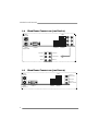
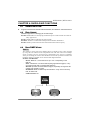
1
NF560 A2G+/NF520 A2G+ Setup Manual FCC Information and Copyright This equipment has been tes ted and found to comply with the limits of a Class B digital devic e, purs uant to Part 15 of the FCC Rules . T hese limits are designed to provide reasonable protec tion against harmful interference in a residential installation. T his equipment generates , uses , and c an radiate radio frequency energy and, if not ins talled and used in accordance with the instructions , may cause harmful interference to radio communications . There is no guarantee that interference will not occur in a particular ins tallation. The vendor makes no representations or warranties with respec t to the contents here and s pecially disclaims any implied warranties of merchantability or fitness for any purpose. Further the vendor reserves the right to revise this publication and to make c hanges to the c ontents here without obligation to notify any party beforehand. D uplication of this publication, in part or in whole, is not allowed without first obtaining the vendor’s approval in writing. The content of this user’s manual is subject to be c hanged without notice and we will not be res ponsible for any mis takes found in this user’s manual. All the brand and produc t names are trademarks of their respec tive companies . Table of Contents Chapter 1: Introduction.....................................................1 1.1 Before You Start................................................................... 1 1.2 Package Checklist................................................................ 1 1.3 Motherboard Features.......................................................... 2 1.4 Rear Panel Connectors (for Ver 5.x)....................................... 4 1.5 Rear Panel Connectors (for Ver 6.x )....................................... 4 1.6 Motherboard Layout ............................................................ 5 Chapter 2: Hardware Installation........................................6 2.1 Installing Central Processing Unit (CPU) ................................ 6 2.2 FAN Headers........................................................................ 8 2.3 Installing System Memory...................................................... 9 2.4 Connectors and Slots ............................................................11 Chapter 3: Headers & Jumpers Setup................................. 13 3.1 How to Setup Jumpers..........................................................13 3.2 Detail Settings.....................................................................13 Chapter 4: NVIDIA RA ID Functions ................................... 19 4.1 Operation System................................................................19 4.2 Raid Arrays.........................................................................19 4.3 How RAID Works.................................................................19 Chapter 5: Useful Help ..................................................... 23 5.1 Driver Installation Note .......................................................23 5.2 Award BIOS Beep Code........................................................24 5.3 Extra Information................................................................24 5.4 Troubleshooting...................................................................25 A ppendencies: SPEC In Other Language............................. 26 German................................................................................................26 France..................................................................................................28 Italian..................................................................................................30 Spanish ................................................................................................32 Portuguese...........................................................................................34 Polish...................................................................................................36 Russian ................................................................................................38 Arabic..................................................................................................40 Japanese ..............................................................................................42 NF560 A2G+/NF520 A2G+ CHAPTER 1: INTRODUCTION 1.1 BEFORE YOU ST ART Thank you for choosing our product. Be fore you start installing the mothe rboard, please make sure you follow the instructions be low: Prepare a dry and stable work ing environment with sufficie nt lighting. Always disconne ct the compute r from powe r outle t be fore ope ration. Before you take the mothe rboard out from anti-static bag, ground yourse lf prope rly by touching any safe ly grounde d appliance, or use grounded wrist strap to remove the static charge. Avoid touching the compone nts on mothe rboard or the rear side of the board unless ne cessary. Hold the board on the edge , do not try to be nd or flex the board. 1.2 Do not leave any unfastene d small parts inside the case afte r installation. Loose parts will cause short circuits which may damage the equipment. Keep the compute r from dange rous a rea, such as hea t source , humid air and wate r. PACKAGE CHECKLIST HDD Cable X 1 Se rial ATA Cable X 1 Rear I/O Panel for ATX Case X 1 Use r’s Manual X 1 Fully Se tup Drive r C D X 1 FDD Cable X 1 (optional) USB 2.0 Cable X1 (optional) S/PDIF out Cable X 1 (optional) Note: The package contents may differ by area or your motherboard version. 1 Motherboard Manual 1.3 MOT HERBOARD FEAT URES NF560 A2G+ Socket AM2 / AM2+ NF520 A2G+ Socket AM2 / AM2+ AMD Athlon 64 / Athlon 64 FX / Athlon 64 X2 / AMD Athlon 64 / Athlon 64 FX / Athlon 64 X2 / CPU FSB Chipset Sempron / AM2+ processors Sempron / AM2+ processors AMD 64 Architecture enables 32 and 64 bit AMD 64 Architecture enables 32 and 64 bit computing computing Supports Hyper Transport and Cool=n=Quiet Supports Hyper Transport and Cool=n=Quiet Support HyperTransport Support HyperTransport Supports up to 1GHz Bandwidth Supports up to 1GHz Bandwidth nVIDIA nForce 560 nVIDIA nForce 520 ITE 8716F ITE 8716F Provides the most commonly used legacy Super Provides the most commonly used legacy Super Super I/O I/O functionality. I/O functionality. Low Pin Count Interface Low Pin Count Interface Environment Control initiatives, Environment Control initiatives, H/W Monitor H/W Monitor Fan Speed Controller Fan Speed Controller ITE's "Smart Guardian" function ITE's "Smart Guardian" function DDR2 DIMM Slot x 4 DDR2 DIMM Slot x 4 Each DIMM supports 256/512/1024/2048 MB Each DIMM supports 256/512/1024/2048 MB DDR2 DDR2 Main Max Memory Capicity 8G Max Memory Capicity 8G Memory Dual Channel Mode DDR2 memory module Dual Channel Mode DDR2 memory module Supports DDR2 533/667/800 Supports DDR2 533/667/800 Registered DIMM and ECC DIMM is not Registered DIMM and ECC DIMM is not supported supported Integrated IDE Controller Integrated IDE Controller IDE SATA LAN 2 Ultra DMA 33 / 66 / 100 / 133 Bus Master Mode Ultra DMA 33 / 66 / 100 / 133 Bus Master Mode supports PIO Mode 0~4, supports PIO Mode 0~4, Integrated Serial ATA Controller Integrated Serial ATA Controller Data transfer rates up to 3.0 Gb/s. Data transfer rates up to 3.0 Gb/s. SATA Version 2.0 specification compliant. SATA Version 2.0 specification compliant. Realtek RTL8111C / RTL8102E (optional) Realtek RTL8111C / RTL8102E (optional) 10 / 100 Mb/s / 1Gb/s auto negotiation (Gigabit 10 / 100 Mb/s / 1Gb/s auto negotiation (Gigabit bandwidth is for Realtek RTL8111C only) bandwidth is for Realtek RTL8111C only) Half / Full duplex capability Half / Full duplex capability NF560 A2G+/NF520 A2G+ NF560 A2G+ Sound Slots NF520 A2G+ ALC888 (Ver 5.x) / ALC662 (Ver 6.x) ALC888 (Ver 5.x) / ALC662 (Ver 6.x) 7.1 channels audio out (ALC888) 7.1 channels audio out (ALC888) 5.1 channels audio out (ALC662) 5.1 channels audio out (ALC662) Supports HD Audio Supports HD Audio PCI slot x3 PCI slot PCI Express x16 slot x1 PCI Express x16 slot x3 x1 PCI Express x 1 slot x2 PCI Express x 1 slot x2 Floppy Connector x1 Floppy Connector x1 Printer Port Connector x1 Printer Port Connector x1 IDE Connector x1 IDE Connector x1 SATA Connector x4 SATA Connector x4 Front Panel Connector x1 Front Panel Connector x1 Front Audio Connector x1 Front Audio Connector x1 On Board CD-in Connector x1 CD-in Connector x1 Connector S/PDIF out Connector x1 S/PDIF out Connector x1 CPU Fan Header x1 CPU Fan Header x1 Back Panel I/O System Fan Header x1 System Fan Header x1 USB Connector x3 USB Connector x3 CMOS clear Header x1 CMOS clear Header x1 Power Connector (24pin) x1 Power Connector (24pin) x1 Power Connector (4pin) x1 Power Connector (4pin) x1 PS/2 Keyboard x1 PS/2 Keyboard x1 PS/2 Mouse x1 PS/2 Mouse x1 Serial Port x1 Serial Port x1 LAN port x1 LAN port x1 USB Port x4 USB Port x4 Audio Jack (Ver 5.x) x6 Audio Jack (Ver 5.x) x6 Audio Jack (Ver 6.x) x3 Audio Jack (Ver 6.x) x3 Board Size 200 mm (W) x 293 mm (L) Special Feature 200 mm (W) x 293 mm (L) RAID 0 / 1 / 0+1 / 5 support RAID 0 / 1 / 0+1 support Windows 2000 / XP / VISTA Windows 2000 / XP / VISTA OS Support Biostar Reserves the right to add or remove support for any OS with or without notice. Biostar Reserves the right to add or remove support for any OS with or without notice. 3 Motherboard Manual 1.4 REAR PANEL CONNECT ORS ( FOR V ER 5.X) PS/2 M ouse PS/2 Key board LAN C OM 1 USBX2 Center 1.5 USBX2 Lin e In Rear Lin e Out Si de Mi c In REAR PANEL CONNECT ORS ( FOR V ER 6.X) PS /2 Mo u se L AN L ine In / S urro un d Lin e O ut Mic I n 1/ B a ss/ Ce nt er PS/ 2 K eyb o ard 4 COM1 USB X2 US BX2 NF560 A2G+/NF520 A2G+ 1.6 MOT HERBOARD LAYOUT JKBMS1 JCFAN1 JATXPWR 2 JCOM1 DIMMB2 DIMMA2 A M2 DIMMA1 Socket JUSB1 DIMMB1 JPRNT1 JATXPWR 1 JUSBLAN1 J AU DIO2 ( fo r Ver 5 .x ) JAUD IO1 (for Ver 6.x) SATA3 SATA4 PEX1_1 PEX1_2 BAT1 J CDIN1 Super I/O SAT A1 SATA2 PEX16_1 Cod ec BIOS L AN IDE1 nForce 520 / 560 JAUD IOF 1 PCI1 J USB2 JU SB3 JUSB4 PCI2 FDD1 JSPDIF_ O UT1 PCI3 JCMOS1 JSFAN1 JPANEL1 st Not e: ■ represe nts the 1 pin. 5 Motherboard Manual CHAPTER 2: HARDWARE INSTALLATION 2.1 INST ALLING CENT RAL PROCESSING UNIT (CPU) Step 1: Remove the socket protection cap. Step 2: Pull the lever toward direction A from the socket and then raise the lever up to a 90-degree angle. Step 3: Look for the white triangle on socket, and the gold triangle on CPU should point forwards this white triangle. The CPU will fit only in the correct orientation. 6 NF560 A2G+/NF520 A2G+ Step 4: Hold the CPU down firmly, and then close the lever toward direct B to complete the installation. Step 5: Put the CPU Fan on the CPU and buckle it. Connect the CPU FAN power cable to the JCFAN1. This completes the installation. Note: Please update the BIOS to the l atest version while using AM2+ CPUs. Due to the latest CPU transition, you may encounter the situation that the new s ys tem fail ed to boot while using new AM2+ CPUs. In this c ase, please i nstall one standar d AM2 CPU to boot your s ystem, and update the latest BIOS from our website for AM2+ CPUs support. 7 Motherboard Manual 2.2 FAN HEADERS These fan headers support cooling-fans built in the computer. The fan cable and connector may be different according to the fan manufacturer. Connect the fan cable to the connector while matching the black wire to pin#1. JCFAN1: CPU Fan Heade r 1 4 Pin 1 2 3 4 Assignment Ground +12V FAN RPM rate sense Smart Fan Control JSFAN1: System Fan He ader Pin 1 2 3 3 Assignment Ground +12V FAN RPM rate sense 1 Note: The JCFAN1 supports 4-pin head connec tor, and JSFAN1s upports 3-pin head c onnector. When connecting with wires onto c onnectors, please note that the red wire is the positive and should be c onnec ted to pin#2, and the blac k wire is Gr ound and should be connected to GND. 8 NF560 A2G+/NF520 A2G+ 2.3 INST ALLING SYST EM MEMORY DIMMA1 DIMMB1 DIMMA2 DIMMB2 A. Memory Modules 1. Unlock a DIMM slot by pressing the retaining clips outward. Align a DIMM on the slot such that the notch on the DIMM matches the break on the Slot. 2. Insert the DIMM vertically and firmly into the slot until the retaining chip snap back in place and the DIMM is properly seated. 9 Motherboard Manual B. Memory Capacity Total Memory Size DIMM Socket Location DIMMA1 256MB/512MB/1024MB/2048MB DIMMB1 256MB/512MB/1024MB/2048MB DIMMA2 256MB/512MB/1024MB/2048MB DIMMB2 256MB/512MB/1024MB/2048MB DDR2 Module Max is 8GB. C. Dual Channel Memory installation To trigger the Dual Channel function of the motherboard, the memory module must meet the following requirements: Install memory module of the same density in pairs, shown in the following table. Dual Channel Status Enabled DIMMA1 O DIMMB1 O DIMMA2 X DIMMB2 X Enabled X X O O Enabled O O O O (O means memory installed, X means memory not installed.) The DRAM bus width of the memory module must be the same (x8 or x16) 10 NF560 A2G+/NF520 A2G+ 2.4 CONNECT ORS AND SLOT S FDD1: Floppy Disk Conne ctor The motherboard prov ides a standard floppy disk connector that supports 360K, 720K, 1.2M, 1.44M and 2.88M floppy disk ty pes. This connector supports the prov ided f loppy drive ribbon cables. 2 34 1 33 IDE1: Hard Disk Conne ctor The motherboard has a 32-bit Enhanced PCI IDE Controller that prov ides PIO Mode 0~4, Bus Master, and Ultra DMA 33/66/100/133 f unctionality. The IDE connector can connect a master and a slave drive, so y ou can connect up to two hard disk driv es. 40 39 2 1 11 Motherboard Manual PEX16_1: PCI-Express x16 Slot - PCI-Express 1.0a compliant. Maximum theoretical realized bandwidth of 4GB/s simultaneously per direction, f or an aggregate of 8GB/s totally. PEX1_1/ PEX1_2: PCI-Express x1 Slots - PCI-Express 1.0a compliant. - Data transf er bandwidth up to 250MB/s per direction; 500MB/s in total. PCI-Express supports a raw bit-rate of 2.5Gb/s on the data pins. 2X bandwidth ov er the traditional PCI architecture. PEX1_1 PEX1_2 PEX16_1 PCI1/PCI2/PCI3: Peripheral Component Interconne ct Slots This motherboard is equipped with 3 standard PCI slots. PCI stands f or Peripheral Component Interconnect, and it is a bus standard for expansion cards. This PCI slot is designated as 32 bits. PCI1 PCI2 PCI3 12 NF560 A2G+/NF520 A2G+ CHAPTER 3: HEADERS & JUMPERS SETUP 3.1 HOW T O SET UP JUMPERS The illustration shows how to set up jumpers. When the jumper cap is placed on pins, the jumper is “close”, if not, that means the jumper is “open”. Pin opened 3.2 Pin closed Pin1-2 closed DET AIL SETT INGS JPANEL1: Front Panel Heade r This 16-pin connector includes Power-on, Reset, HDD LED, Power LED, speaker Connection. It allows user to connect the PC case’s front panel switch functions. PWR_LED On/Off ++ 9 1 + SPK Pin 1 2 3 4 5 6 7 8 Assignment +5V N/A N/A Speaker HDD LED (+) HDD LED (-) Ground Reset control Functio n Speaker Connector Hard drive LED Reset button Pin 9 10 11 12 13 14 15 16 16 8 RST HLED Assignment N/A N/A N/A Power LED (+) Power LED (+) Power LED (-) Power button Ground Functio n N/A N/A Power LED Power-on button 13 Motherboard Manual ATX Powe r Source Conne ctor: JATXPWR1 JATXPWR1 allows user to connect 24-pin power connector on the ATX power supply. Pin Assignment 1 2 3 4 5 6 7 8 9 10 11 12 +3.3V +3.3V Ground +5V Ground +5V Ground PW_OK Standby Voltage+5V +12V +12V +3.3V Pin 12 24 1 13 Assignment 13 14 15 16 17 18 19 20 21 22 23 24 +3.3V -12V Ground PS_ON Ground Ground Ground NC +5V +5V +5V Ground JATXPWR2: ATX Powe r Source Conne ctor By connecting this connector, it will provide +12V to CPU power circuit. 2 1 3 4 Pin 1 2 3 4 14 Assignment +12V +12V Ground Ground NF560 A2G+/NF520 A2G+ JUSB2/JUSB3/JUSB4: He ade rs for USB 2.0 Ports at Front Panel This header allows user to connect additional USB cable on the PC f ront panel, and also can be connected with internal USB devices, like USB card reader. JUSB2 JUSB3 JUSB4 2 10 1 9 Pin 1 2 3 4 5 6 7 8 9 10 Assignment +5V (fused) +5V (fused) USBUSBUSB+ USB+ Ground Ground Key NC SATA1/SATA2/SATA3/SATA4: Se rial ATA Conne ctors The motherboard has a PCI to SATA Controller with 4 channels SATA interf ace, it satisfies the SATA 2.0 spec and with transfer rate of 3.0Gb/s. SATA3 SATA4 SATA1 SATA2 7 4 Pin 1 2 3 4 5 6 7 Assignment Ground T X+ T XGround RXRX+ Ground 1 15 Motherboard Manual JAUDIO F1: Front Panel Audio Heade r This header allows user to connect the front audio output cable with the PC f ront panel. This header allows only HD audio front panel connector; AC’97 connector is not acceptable. 1 2 9 10 Pin 1 2 3 4 5 6 7 8 9 10 Assignment Mic Left in Ground Mic Right in GPIO Right line in Jack Sense Front Sense Key Left line in Jack Sense JCDIN1: CD-RO M Audio-in Connector This connector allows user to connect the audio source f rom the v ariaty dev ices, like CD-ROM, DVD-ROM, PCI sound card, PCI TV turner card etc. Pin 1 4 16 1 2 3 4 Assignment Left Channel Input Ground Ground Right Channel Input NF560 A2G+/NF520 A2G+ JSPDIF_O UT1: Digital Audio-out Conne ctor This connector allows user to connect the PCI bracket SPDIF output header. Pin 1 2 3 3 Assignment +5V SPDIF_OUT Ground 1 JCMO S1: Cle ar CMOS Heade r By placing the jumper on pin2-3, it allows user to restore the BIOS saf e setting and the CMOS data, please carefully f ollow the procedures to avoid damaging the motherboard. 1 3 Pin 1-2 Close: Normal Operation (default). 1 1 3 3 Pin 2-3 Close: Clear CMOS data. ※ Clear CMOS Proce dures: 1. 2. 3. 4. 5. 6. Remov e AC power line. Set the jumper to “Pin 2-3 close”. Wait f or f ive seconds. Set the jumper to “Pin 1-2 close”. Power on the AC. Reset y our desired password or clear the CMOS data. 17 Motherboard Manual JPRNT1: Printe r Port Connector This header allows you to connector printer on the PC. 1 2 25 Pin 1 2 3 4 5 6 7 8 9 10 11 12 13 18 Assignment -Strobe -ALF Data 0 -Error Data 1 -Init Data 2 -Scltin Data 3 Ground Data 4 Ground Data 5 Pin 14 15 16 17 18 19 20 21 22 23 24 25 26 Assignment Ground Data 6 Ground Data 7 Ground -ACK Ground Busy Ground PE Ground SCLT Key NF560 A2G+/NF520 A2G+ CHAPTER 4: NVIDIA RAID FUNCTIONS 4.1 O PERAT ION SYST EM z Supports Windows XP Home/Prof essional Edition, and Windows 2000 Prof essional. 4.2 RAID ARRAYS NVRAID supports the f ollowing ty pes of RAID arrays: RAID 0: RAID 0 defines a disk striping scheme that improves disk read and write times for many applications. RAID 1: RAID 1 defines techniques for mirroring data. RAID 0+1: RAID 0+1 combines the techniques used in RAID 0 and RAID 1. RAID 5: RAID 5 provides fault tolerance and better utilization of disk capacity. 4.3 HOW RAID WORKS RAID 0: The controller “ stripes” data across multiple drives in a RAID 0 array system. It breaks up a large file into smaller blocks and performs disk reads and writes across multiple drives in parallel. The size of each block is determined by the stripe size parameter, which you set during the creation of the RAID set based on the system environment. This technique reduces overall disk access time and offers high bandwidth. Features and Benefits Drives: Minimum 1, and maximum is up to 6 or 8. Depending on the platf orm. Uses: Intended for non-critical data requiring high data throughput, or any env ironment that does not require f ault tolerance. Benefits: prov ides increased data throughput, especially f or large files. No capacity loss penalty f or parity. Drawbacks: Does not deliver any fault tolerance. If any drive in the array f ails, all data is lost. Fault Tolerance: No. Block 1 Blo ck 3 Blo ck 5 Bl ock 2 Block 4 Block 6 19 Motherboard Manual RAID 1: Every read and write is actually carried out in parallel across 2 disk drives in a RAID 1 array system. The mirrored (backup) copy of the data can reside on the same disk or on a second redundant drive in the array. RAID 1 provides a hot-standby copy of data if the active volume or drive is corrupted or becomes unavailable because of a hardware failure. RAID techniques can be applied for high-availability solutions, or as a form of automatic backup that eliminates tedious manual backups to more expensive and less reliable media. Features and Benefits Drives: Minimum 2, and maximum is 2. Uses: RAID 1 is ideal f or small databases or any other application that requires f ault tolerance and minimal capacity. Benefits: Prov ides 100% data redundancy. Should one driv e f ail, the controller switches to the other drive. Drawbacks: Requires 2 driv es for the storage space of one driv e. Perf ormance is impaired during driv e rebuilds. Fault Tolerance: Yes. Block 1 Block 2 Block 3 20 Block 1 Block 2 Block 3 NF560 A2G+/NF520 A2G+ RAID 0+1: RAID 0 drives can be mirrored using RAID 1 techniques. Resulting in a RAID 0+1 solution for improved performance plus resiliency. Features and Benefits Drives: Minimum 4, and maximum is 6 or 8, depending on the platform. Benefits: Optimizes for both fault tolerance and perf ormance, allowing for automatic redundancy. May be simultaneously used with other RAID lev els in an array, and allows for spare disks. Drawbacks: Requires twice the available disk space f or data redundancy, the same as RAID level 1. Fault Tolerance: Yes. Block 1 Bl ock 3 Bl ock 5 Blo ck 2 Blo ck 4 Blo ck 6 Blo ck 1 Block 3 Block 5 Block 2 Block 4 Block 6 21 Motherboard Manual RAID 5: RAID 5 stripes both data and parity information across three or more drives. It writes data and parity blocks across all the drives in the array. Fault tolerance is maintained by ensuring that the parity information for any given block of data is placed on a different drive from those used to store the data itself. Features and Benefits Drives: Minimum 3. Uses: RAID 5 is recommended for transaction processing and general purpose service. Benefits: An ideal combination of good performance, good fault tolerance, and high capacity and storage efficiency. Drawbacks: Individual block data transfer rate same as a single disk. Write perf ormance can be CPU intensiv e. Fault Tolerance: Yes. Disk 1 DATA 1 DATA 3 PARITY DATA 7 DATA 9 PARITY Disk 2 DATA 2 PARITY DATA 5 DATA 8 PARITY DATA 11 Disk 3 PARITY DATA 4 DATA 6 PARITY DATA 10 DATA 12 ※ 22 For more detailed setup information, please refer to the Driver CD, or go to http://www.nvidia.com/object/IO_28159.html to download the NVIDIA RAID User’s Guide. NF560 A2G+/NF520 A2G+ CHAPTER 5: USEFUL HELP 5.1 DRIVER INST ALLAT ION NOT E After you installed your operating system, please insert the Fully Setup Driver CD into your optical drive and install the driver for better system performance. You will see the following window after you insert the CD The setup guide will auto detect your motherboard and operating system. Note: If this window didn’t show up after you ins ert the Driver CD, please use file brows er to locate and execute the file SETUP.EXE under your optical drive. A. Driver Installation To install the driver, please click on the Driver icon. The setup guide will list the compatible driver for your motherboard and operating system. Click on each device driver to launch the installation program. B. Software Installation To install the software, please click on the Software icon. The setup guide will list the software available for your system, click on each software title to launch the installation program. C. Manual Aside from the paperback manual, we also provide manual in the Driver CD. Click on the Manual icon to browse for available manual. Note: You will need Acrobat R eader to open the manual file. Pleas e download the latest version of Acrobat Reader software from http://www.adobe.com/products/acrobat/readstep 2.html 23 Motherboard Manual 5.2 AWARD BIOS BEEP CODE Beep Sound One long beep followed by two short beeps High-low siren sound Meaning Video card not found or v ideo card memory bad CPU overheated System will shut down automatically One Short beep when system boot-up No error found during POST Long beeps every other second No DRAM detected or install 5.3 EXT RA INFORMAT ION CPU Overheated If the system shutdown automatically after power on system for seconds, that means the CPU protection function has been activated. When the CPU is over heated, the motherboard will shutdown automatically to avoid a damage of the CPU, and the system may not power on again. In this case, please double check: 1. The CPU cooler surface is placed evenly with the CPU surface. 2. CPU fan is rotated normally. 3. CPU fan speed is fulfilling with the CPU speed. After confirmed, please follow steps below to relief the CPU protection function. 1. Remove the power cord from power supply for seconds. 2. Wait for seconds. 3. Plug in the power cord and boot up the system. Or you can: 1. Clear the CMOS data. (See “Close CMOS Header: JCMOS1” section) 2. Wait for seconds. 3. Power on the system again. 24 NF560 A2G+/NF520 A2G+ 5.4 TROUBLESHOOT ING Probable Solution 1. Make sure power cable is No power to the system at all securely plugged in. Power light don’t illuminate, f an inside power supply does not turn 2. Replace cable. on. 3. Contact technical support. 2. Indicator light on key board does not turn on. System inoperativ e. Keyboard lights Using even pressure on both ends of are on, power indicator lights are lit, the DIMM, press down firmly until the and hard driv e is spinning. module snaps into place. 1. System does not boot from hard disk 1. driv e, can be booted f rom optical driv e. Check cable running from disk to disk controller board. Make sure both ends are securely plugged in; check the driv e type in the standard CMOS setup. 2. Backing up the hard drive is extremely important. All hard disks are capable of breaking down at any time. 1. Back up data and applications System only boots f rom optical driv e. f iles. Hard disk can be read and applications can be used but booting from hard disk 2. Ref ormat the hard driv e. is impossible. Re-install applications and data using backup disks. Screen message says “Invalid Rev iew system’s equipment. Make sure Conf iguration” or “CMOS Failure.” correct inf ormation is in setup. Cannot boot system after installing 1. Set master/slave jumpers second hard driv e. correctly. 2. Run SETUP program and select correct driv e types. Call the drive manuf acturers f or compatibility with other drives. 25 Motherboard Manual APPENDENCIES: SPEC IN OTHER LANGUAGE GERMAN NF560 A2G+ Sockel AM2 / AM2+ NF520 A2G+ Sockel AM2 / AM2+ AMD Athlon 64 / Athlon 64 FX / Athlon 64 X2 / AMD Athlon 64 / Athlon 64 FX / Athlon 64 X2 / CPU FSB Chipsatz Super E/A Sempron / AM2+ Prozessoren Sempron / AM2+ Prozessoren Die AMD 64-Architektur unterstützt eine 32-Bit- Die AMD 64-Architektur unterstützt eine 32-Bitund 64-Bit-Datenverarbeitung und 64-Bit-Datenverarbeitung Unterstützt Hyper Transport und Cool’n’Quiet Unterstützt Hyper Transport und Cool’n’Quiet Unterstützt HyperTransport mit einer Unterstützt HyperTransport mit einer Bandbreite von bis zu 1 GHz Bandbreite von bis zu 1 GHz nVIDIA nForce 560 nVIDIA nForce 520 ITE 8716F ITE 8716F Bietet die häufig verwendeten alten Super Bietet die häufig verwendeten alten Super E/A-Funktionen. E/A-Funktionen. Low Pin Count-Schnittstelle Low Pin Count-Schnittstelle Umgebungskontrolle, Umgebungskontrolle, Hardware-Überwachung Hardware-Überwachung Lüfterdrehzahl-Controller Lüfterdrehzahl-Controller "Smart Guardian"-Funktion von ITE "Smart Guardian"-Funktion von ITE DDR2 DIMM-Steckplätze x 4 DDR2 DIMM-Steckplätze x 4 Jeder DIMM unterstützt 256MB/512MB/1GB/ Jeder DIMM unterstützt 256MB/512MB/1GB/ 2GB DDR2. 2GB DDR2. Arbeitsspeiche Max. 8GB Arbeitsspeicher Max. 8GB Arbeitsspeicher r Dual-Kanal DDR2 Speichermodul Dual-Kanal DDR2 Speichermodul Unterstützt DDR2 533 / 667 / 800 Unterstützt DDR2 533 / 667 / 800 registrierte DIMMs. ECC DIMMs werden nicht registrierte DIMMs. ECC DIMMs werden nicht unterstützt. unterstützt. Integrierter IDE-Controller Integrierter IDE-Controller Ultra DMA 33 / 66 / 100 / 133 Bus Ultra DMA 33 / 66 / 100 / 133 Bus Master-Modus Master-Modus Unterstützt PIO-Modus 0~4, Unterstützt PIO-Modus 0~4, Integrierter Serial ATA-Controller Integrierter Serial ATA-Controller Datentransferrate bis zu 3Gb/s Datentransferrate bis zu 3Gb/s Konform mit der SATA-Spezifikation Version Konform mit der SATA-Spezifikation Version 2.0. 2.0. Realtek RTL8111C / RTL8102E(optional) Realtek RTL8111C / RTL8102E(optional) 10 / 100 / 1000 Mb/s Auto-Negotiation 10 / 100 / 1000 Mb/s Auto-Negotiation (Gigabit-Bandbreite nur beim Realtek (Gigabit-Bandbreite nur beim Realtek RTL8111C) RTL8111C) Halb-/ Vollduplex-Funktion Halb-/ Vollduplex-Funktion IDE SATA II LAN 26 NF560 A2G+/NF520 A2G+ NF560 A2G+ Audio-Codec NF520 A2G+ ALC888 (Ver 5.x) / ALC662 (Ver 6.x) ALC888 (Ver 5.x) / ALC662 (Ver 6.x) 7.1-Kanal-Audioausgabe (ALC888) 7.1-Kanal-Audioausgabe (ALC888) 5.1-Kanal-Audioausgabe (ALC662) 5.1-Kanal-Audioausgabe (ALC662) Unterstützt High-Definition Audio Unterstützt High-Definition Audio PCI-Steckplatz x3 PCI-Steckplatz PCI Express x16 Steckplatz x1 PCI Express x16 Steckplatz x1 PCI Express x 1-Steckplatz x2 PCI Express x 1-Steckplatz x2 Diskettenlaufwerkanschluss x1 Diskettenlaufwerkanschluss x1 Druckeranschluss Anschluss x1 Druckeranschluss Anschluss x1 IDE-Anschluss x1 IDE-Anschluss x1 SATA-Anschluss x4 SATA-Anschluss x4 Fronttafelanschluss x1 Fronttafelanschluss x1 Front-Audioanschluss x1 Front-Audioanschluss x1 Onboard-Ansc CD-IN-Anschluss x1 CD-IN-Anschluss x1 hluss S/PDIF- Ausgangsanschluss x1 S/PDIF- Ausgangsanschluss x1 CPU-Lüfter-Sockel x1 CPU-Lüfter-Sockel x1 Steckplätze Rückseiten-E/ A System-Lüfter-Sockel x1 System-Lüfter-Sockel x1 "CMOS löschen"-Sockel x1 "CMOS löschen"-Sockel x1 USB-Anschluss x3 USB-Anschluss x3 Stromanschluss (24-polig) x1 Stromanschluss (24-polig) x1 Stromanschluss (4-polig) x1 Stromanschluss (4-polig) x1 PS/2-Tastatur x1 PS/2-Tastatur x1 PS/2-Maus x1 PS/2-Maus x1 Serieller Anschluss x1 Serieller Anschluss x1 LAN-Anschluss x1 LAN-Anschluss x1 USB-Anschluss x4 USB-Anschluss x4 Audioanschluss (Ver 5.x) x6 Audioanschluss (Ver 5.x) x6 Audioanschluss (Ver 6.x) x3 Audioanschluss (Ver 6.x) x3 Platinengröße. 200 mm (B) X 293 mm (L) Sonderfunktio nen OS-Unterstütz ung x3 200 mm (B) X 293 mm (L) Unterstützt RAID 0 / 1 / 0+1 / 5 Unterstützt RAID 0 / 1 / 0+1 Windows 2K / XP / VISTA Windows 2K / XP / VISTA Biostar behält sich das Recht vor, ohne Biostar behält sich das Recht vor, ohne Ankündigung die Unterstützung für ein Ankündigung die Unterstützung für ein Betriebssystem hinzuzufügen oder zu Betriebssystem hinzuzufügen oder zu entfernen. entfernen. 27 Motherboard Manual FRANCE NF560 A2G+ UC NF520 A2G+ Socket AM2 / AM2+ Socket AM2 / AM2+ Processeurs AMD Athlon 64 / Athlon 64 FX / Processeurs AMD Athlon 64 / Athlon 64 FX / Athlon 64 X2 / Sempron / AM2+ Athlon 64 X2 / Sempron / AM2+ L'architecture AMD 64 permet le calcul 32 et 64 L'architecture AMD 64 permet le calcul 32 et 64 bits bits Prend en charge Hyper Transport et Cool’n’Quiet Prend en charge Hyper Transport et Cool’n’Quiet Bus frontal Chipset Super E/S Mémoire principale IDE SATA II Prend en charge Hyper Transport jusqu'à une Prend en charge Hyper Transport jusqu'à une bande passante de 1G bande passante de 1G nVIDIA nForce 560 nVIDIA nForce 520 ITE 8716F ITE 8716F Fournit la fonctionnalité de Super E/S Fournit la fonctionnalité de Super E/S patrimoniales la plus utilisée. patrimoniales la plus utilisée. Interface à faible compte de broches Interface à faible compte de broches Initiatives de contrôle environnementales, Initiatives de contrôle environnementales, Moniteur de matériel Moniteur de matériel Contrôleur de vitesse de ventilateur Contrôleur de vitesse de ventilateur Fonction "Gardien intelligent" de l'ITE Fonction "Gardien intelligent" de l'ITE Fentes DDR2 DIMM x 4 Fentes DDR2 DIMM x 4 Chaque DIMM prend en charge des DDR2 de Chaque DIMM prend en charge des DDR2 de 256/512 Mo et 1Go/2Go 256/512 Mo et 1Go/2Go Capacité mémoire maximale de 8 Go Capacité mémoire maximale de 8 Go Module de mémoire DDR2 à mode à double voie Module de mémoire DDR2 à mode à double voie Prend en charge la DDR2 533 / 667 / 800 Prend en charge la DDR2 533 / 667 / 800 Les DIMM à registres et DIMM avec code Les DIMM à registres et DIMM avec code correcteurs d'erreurs ne sont pas prises en correcteurs d'erreurs ne sont pas prises en charge charge Contrôleur IDE intégré Contrôleur IDE intégré Mode principale de Bus Ultra DMA 33 / 66 / 100 / Mode principale de Bus Ultra DMA 33 / 66 / 100 / 133 133 Prend en charge le mode PIO 0~4, Prend en charge le mode PIO 0~4, Contrôleur Serial ATA intégré : Contrôleur Serial ATA intégré : Taux de transfert jusqu'à 3 Go/s. Taux de transfert jusqu'à 3 Go/s. Conforme à la spécification SATA Version 2.0 Conforme à la spécification SATA Version 2.0 Realtek RTL8111C / RTL8102E(optional) Realtek RTL8111C / RTL8102E(optional) 10 / 100 / 1000 Mb/s négociation automatique 10 / 100 / 1000 Mb/s négociation automatique LAN 28 (La bande passante Gigabit est pour le Realtek (La bande passante Gigabit est pour le Realtek RTL8111C uniquement) RTL8111C uniquement) Half / Full duplex capability Half / Full duplex capability NF560 A2G+/NF520 A2G+ NF560 A2G+ Codec audio Fentes NF520 A2G+ ALC888 (Ver 5.x) / ALC662 (Ver 6.x) ALC888 (Ver 5.x) / ALC662 (Ver 6.x) Sortie audio à 7.1 voies (ALC888) Sortie audio à 7.1 voies (ALC888) Sortie audio à 5.1 voies (ALC662) Sortie audio à 5.1 voies (ALC662) Prise en charge de l'audio haute définition Prise en charge de l'audio haute définition Fente PCI x3 Fente PCI x3 x1 Slot PCI Express x16 x1 Slot PCI Express x16 Slot PCI Express x 1 x2 Slot PCI Express x 1 x2 Connecteur de disquette x1 Connecteur de disquette x1 Connecteur de Port d'imprimante x1 Connecteur de Port d'imprimante x1 Connecteur IDE x1 Connecteur IDE x1 Connecteur SATA x4 Connecteur SATA x4 Connecteur du panneau avant x1 Connecteur du panneau avant x1 Connecteur Audio du panneau avant x1 Connecteur Audio du panneau avant x1 Connecteur d'entrée CD x1 Connecteur d'entrée CD x1 Connecteur Connecteur de sortie S/PDIF x1 Connecteur de sortie S/PDIF x1 embarqué Embase de ventilateur UC x1 Embase de ventilateur UC x1 Embase de ventilateur système x1 Embase de ventilateur système x1 Embase d'effacement CMOS x1 Embase d'effacement CMOS x1 Connecteur USB x3 Connecteur USB x3 Connecteur d'alimentation x1 Connecteur d'alimentation x1 x1 Connecteur d'alimentation (24 broches) Connecteur d'alimentation (24 broches) (4 broches) Clavier PS/2 x1 (4 broches) x1 Clavier PS/2 x1 Souris PS/2 x1 Souris PS/2 x1 E/S du Port série x1 Port série x1 panneau Port LAN x1 Port LAN x1 arrière Port USB x4 Port USB x4 Fiche audio (Ver 5.x) x6 Fiche audio (Ver 5.x) x6 Fiche audio (Ver 6.x) x3 Fiche audio (Ver 6.x) x3 Dimensions de la carte 200 mm (l) X 293 mm (H) 200 mm (l) X 293 mm (H) Fonctionnali tés Prise en charge RAID 0 / 1 / 0+1 / 5 Prise en charge RAID 0 / 1 / 0+1 Windows 2K / XP / VISTA Windows 2K / XP / VISTA spéciales Support SE Biostar se réserve le droit d'ajouter ou de Biostar se réserve le droit d'ajouter ou de supprimer le support de SE avec ou sans préavis. supprimer le support de SE avec ou sans préavis. 29 Motherboard Manual IT ALIAN NF560 A2G+ Socket AM2 / AM 2+ NF520 A2G+ Socket AM2 / AM 2+ Processori AMD Athlon 64 / Athlon 64 FX / Processori AMD Athlon 64 / Athlon 64 FX / CPU Athlon 64 X 2 / Sempron / AM2+ Athlon 64 X 2 / Sempron / AM2+ L’architettura AMD 64 abilita l a L’architettura AMD 64 abilita l a computazione 32 e 64 bit computazione 32 e 64 bit Supporto di Hyper Tra nsport e Cool’ n’Quiet Supporto di Hyper Tra nsport e Cool’ n’Quiet FSB Chipset Super I/O Supporto di Hyper Transport fi no a 1G di Supporto di Hyper Transport fi no a 1G di larghezza di ba nda larghezza di ba nda nVIDIA nForce 560 nVIDIA nForce 520 ITE 8716F ITE 8716F Fornisce le funzio nalità legacy Super I/O Fornisce le funzio nalità legacy Super I/O usate più comunemente. usate più comunemente. Interfaccia LPC (L ow Pin Count) Interfaccia LPC (L ow Pin Count) Funzioni di co ntrollo dell’ambiente: Funzioni di co ntrollo dell’ambiente: Monitoraggio hardware Monitoraggio hardware Controller velocità ventolina Controller velocità ventolina Funzione "Smart Guardi an" di I TE Funzione "Smart Guardi an" di I TE Alloggi DIMM DDR 2 x 4 Alloggi DIMM DDR 2 x 4 Ciascun DIMM supporta DDR2 256/ 512MB e Ciascun DIMM supporta DDR2 256/ 512MB e 1GB/2GB 1GB/2GB Memoria Capacità massima della memori a 8GB Capacità massima della memori a 8GB principale Modulo di memoria DDR2 a canale doppio Modulo di memoria DDR2 a canale doppio Supporto di DDR2 533 / 667 / 800 Supporto di DDR2 533 / 667 / 800 DIMM registrati e DIMM ECC no n sono DIMM registrati e DIMM ECC no n sono supportati supportati Controller IDE i ntegrato Controller IDE i ntegrato Modalità Bus Master Ultra DMA 33 / 66 / Modalità Bus Master Ultra DMA 33 / 66 / 100 / 133 100 / 133 Supporto modalità PIO Mode 0- 4 Supporto modalità PIO Mode 0- 4 Controller Serial ATA inte grato Controller Serial ATA inte grato Velocità di trasferimento dei dati fi no a 3 Velocità di trasferimento dei dati fi no a 3 Gb/s. Gb/s. Compatibile specifiche SATA Versione 2.0. Compatibile specifiche SATA Versione 2.0. Realtek RTL8111C / RTL8102E(optional) Realtek RTL8111C / RTL8102E(optional) Negoziazione automatica 10 / 100 / 1000 Negoziazione automatica 10 / 100 / 1000 Mb/s (la lar ghezza di banda Gigabit è solo Mb/s (la lar ghezza di banda Gigabit è solo per Realtek RTL8111C) per Realtek RTL8111C) Capacità Half / Full Duplex Capacità Half / Full Duplex IDE SATA II LAN 30 NF560 A2G+/NF520 A2G+ NF560 A2G+ NF520 A2G+ ALC888 (Ver 5.x) / ALC662 (Ver 6.x) ALC888 (Ver 5.x) / ALC662 (Ver 6.x) Codec Uscita audio 7.1 ca nali (ALC888) Uscita audio 7.1 ca nali (ALC888) audio Uscita audio 5.1 ca nali (ALC662) Uscita audio 5.1 ca nali (ALC662) Supporto audio High- Defi nition (HD) Supporto audio High- Defi nition (HD) Alloggio PCI x3 Alloggio PCI Alloggio PCI Ex press x16 x1 Alloggio PCI Ex press x16 x1 Alloggio PCI Ex press x1 x2 Alloggio PCI Ex press x1 x2 Connettore flo ppy x1 Connettore flo ppy x1 Connettore Porta stampa nte x1 Connettore Porta stampa nte x1 Connettore IDE x1 Connettore IDE x1 Alloggi x3 Connettore SATA x4 Connettore SATA x4 Connettore pa nnello fro ntale x1 Connettore pa nnello fro ntale x1 Connettore audio frontale x1 Connettore audio frontale x1 Connettore CD-in x1 Connettore CD-in x1 Connettori Connettore output SPDIF x1 Connettore output SPDIF x1 su scheda Collettore ventolina CPU x1 Collettore ventolina CPU x1 Collettore ventolina sistema x1 Collettore ventolina sistema x1 Collettore cancellazione CMOS x1 Collettore cancellazione CMOS x1 Connettore USB x3 Connettore USB x3 Connettore alimentazione x1 Connettore alimentazione x1 (24 pin) Connettore alimentazione (24 pin) x1 (4 pi n) Tastiera PS/2 Connettore alimentazione x1 (4 pi n) x1 Tastiera PS/2 x1 Mouse PS/2 x1 Mouse PS/2 x1 I/O Porta seriale x1 Porta seriale x1 pannello Porta LAN x1 Porta LAN x1 posteriore Porta USB x4 Porta USB x4 Connettore audio (Ver 5.x) x6 Connettore audio (Ver 5.x) x6 Connettore audio (Ver 6.x) x3 Connettore audio (Ver 6.x) x3 Dimension i scheda 200 mm (lar ghezza) x 293 mm (altezza) 200 mm (lar ghezza) x 293 mm (altezza) Supporto RAID 0 / 1 / 0+1 / 5 Supporto RAID 0 / 1 / 0+1 Windows 2K / XP / VISTA Windows 2K / XP / VISTA Biostar si riserva il diritto di aggiungere o Biostar si riserva il diritto di aggiungere o rimuovere il supporto di qualsiasi sistema rimuovere il supporto di qualsiasi sistema operativo se nza pre avviso. operativo se nza pre avviso. Caratterist iche speciali Sistemi operativi supportati 31 Motherboard Manual SPANISH NF560 A2G+ CPU FSB Conjunto de chips NF520 A2G+ Conector AM2 / AM2+ Conector AM2 / AM2+ Procesadores AMD Athlon 64 / Athlon 64 FX / Procesadores AMD Athlon 64 / Athlon 64 FX / Athlon 64 X2 / Sempron / AM2+ Athlon 64 X2 / Sempron / AM2+ La arquitectura AMD 64 permite el procesado de La arquitectura AMD 64 permite el procesado de 32 y 64 bits 32 y 64 bits Soporta las tecnologías Hyper Transport y Soporta las tecnologías Hyper Transport y Cool’n’Quiet Cool’n’Quiet Admite HyperTransport con un ancho de banda Admite HyperTransport con un ancho de banda de hasta 1G de hasta 1G nVIDIA nForce 560 nVIDIA nForce 520 ITE 8716F ITE 8716F Le ofrece las funcionalidades heredadas de uso Le ofrece las funcionalidades heredadas de uso más común Súper E/S. más común Súper E/S. Interfaz de cuenta Low Pin Interfaz de cuenta Low Pin Iniciativas de control de entorno, Iniciativas de control de entorno, Monitor hardware Monitor hardware Controlador de velocidad de ventilador Controlador de velocidad de ventilador Función "Guardia inteligente" de ITE Función "Guardia inteligente" de ITE Ranuras DIMM DDR2 x 4 Ranuras DIMM DDR2 x 4 Cada DIMM admite DDR de 256/512MB y Cada DIMM admite DDR de 256/512MB y 1GB/2GB 1GB/2GB Memoria Capacidad máxima de memoria de 8GB Capacidad máxima de memoria de 8GB principal Módulo de memoria DDR2 de canal Doble Módulo de memoria DDR2 de canal Doble Admite DDR2 de 533 / 667 / 800 Admite DDR2 de 533 / 667 / 800 No admite DIMM registrados o DIMM No admite DIMM registrados o DIMM compatibles con ECC compatibles con ECC Controlador IDE integrado Controlador IDE integrado Súper E/S IDE SATA II Modo bus maestro Ultra DMA 33 / 66 / 100 / 133 Modo bus maestro Ultra DMA 33 / 66 / 100 / 133 Soporte los Modos PIO 0~4, Soporte los Modos PIO 0~4, Controlador ATA Serie Integrado Controlador ATA Serie Integrado Tasas de transferencia de hasta 3 Gb/s. Tasas de transferencia de hasta 3 Gb/s. Compatible con la versión SATA 2.0. Compatible con la versión SATA 2.0. Realtek RTL8111C / RTL8102E (opcional) Realtek RTL8111C / RTL8102E (opcional) Negociación de 10 / 100 / 1000 Mb/s (el ancho Negociación de 10 / 100 / 1000 Mb/s (el ancho Red Local 32 de banda Gigabit es únicamente para Realtek de banda Gigabit es únicamente para Realtek RTL8111C) RTL8111C) Funciones Half / Full dúplex Funciones Half / Full dúplex NF560 A2G+/NF520 A2G+ NF560 A2G+ NF520 A2G+ ALC888 (Ver 5.x) / ALC662 (Ver 6.x) ALC888 (Ver 5.x) / ALC662 (Ver 6.x) Códecs de Salida de sonido de 7.1 canales (ALC888) Salida de sonido de 7.1 canales (ALC888) sonido Salida de sonido de 5.1 canales (ALC662) Salida de sonido de 5.1 canales (ALC662) Soporte de sonido de Alta Definición Soporte de sonido de Alta Definición Ranuras Ranura PCI X3 Ranura PCI X3 Ranura PCI Express x16 X1 Ranura PCI Express x16 X1 Ranura PCI express x 1 X2 Ranura PCI express x 1 X2 Conector disco flexible X1 Conector disco flexible X1 Conector Puerto de impresora X1 Conector Puerto de impresora X1 Conector IDE X1 Conector IDE X1 Conector SATA X4 Conector SATA X4 Conector de panel frontal X1 Conector de panel frontal X1 Conector de sonido frontal X1 Conector de sonido frontal X1 X1 Conector de entrada de CD X1 Conectores Conector de salida S/PDIF Conector de entrada de CD X1 Conector de salida S/PDIF X1 en placa X1 Cabecera de ventilador de CPU X1 Cabecera de ventilador de CPU Cabecera de ventilador de sistema X1 Cabecera de ventilador de sistema X1 Cabecera de borrado de CMOS X1 Cabecera de borrado de CMOS X1 Conector USB X3 Conector USB X3 Conector de alimentación X1 Conector de alimentación X1 X1 Conector de alimentación (24 patillas) Conector de alimentación (24 patillas) (4 patillas) Teclado PS/2 X1 (4 patillas) X1 Teclado PS/2 X1 Ratón PS/2 X1 Ratón PS/2 X1 Panel Puerto serie X1 Puerto serie X1 trasero de Puerto de red local X1 Puerto de red local X1 E/S Puerto USB X4 Puerto USB X4 Conector de sonido (Ver 5.x) X6 Conector de sonido (Ver 5.x) X6 Conector de sonido (Ver 6.x) X3 Conector de sonido (Ver 6.x) X3 Tamaño de la placa Funciones especiales 200 mm. (A) X 293 mm. (H) 200 mm. (A) X 293 mm. (H) Admite RAID 0 / 1 / 0+1 / 5 Admite RAID 0 / 1 / 0+1 Soporte de Windows 2K / XP / VISTA Windows 2K / XP / VISTA sistema Biostar se reserva el derecho de añadir o retirar Biostar se reserva el derecho de añadir o retirar operativo el soporte de cualquier SO con o sin aviso previo. el soporte de cualquier SO con o sin aviso previo. 33 Motherboard Manual PORT UGUESE NF560 A2G+ CPU FSB Chipset NF520 A2G+ Socket AM2 / AM2+ Socket AM2 / AM2+ Processadores AMD Athlon 64 / Athlon 64 FX / Processadores AMD Athlon 64 / Athlon 64 FX / Athlon 64 X2 / Sempron / AM2+ Athlon 64 X2 / Sempron / AM2+ A arquitectura AMD 64 permite uma computação A arquitectura AMD 64 permite uma computação de 32 e 64 bits de 32 e 64 bits Suporta as tecnologias Hyper Transport e Suporta as tecnologias Hyper Transport e Cool’n’Quiet Cool’n’Quiet Suporta a tecnologia HyperTransport com uma Suporta a tecnologia HyperTransport com uma largura de banda até 1G largura de banda até 1G nVIDIA nForce 560 nVIDIA nForce 520 ITE 8716F ITE 8716F Proporciona as funcionalidades mais utilizadas Proporciona as funcionalidades mais utilizadas em termos da especificação Super I/O. em termos da especificação Super I/O. Especificaçã Interface LPC (Low Pin Count). Interface LPC (Low Pin Count). o Super I/O Iniciativas para controlo do ambiente Iniciativas para controlo do ambiente Monitorização do hardware Monitorização do hardware Controlador da velocidade da ventoinha Controlador da velocidade da ventoinha Função "Smart Guardian" da ITE Função "Smart Guardian" da ITE Ranhuras DIMM DDR2 x 4 Ranhuras DIMM DDR2 x 4 Cada módulo DIMM suporta uma memória Cada módulo DIMM suporta uma memória DDR2 de 256/512 MB & 1 GB/2 GB DDR2 de 256/512 MB & 1 GB/2 GB Memória Capacidade máxima de memória: 8 GB Capacidade máxima de memória: 8 GB principal Módulo de memória DDR2 de canal duplo Módulo de memória DDR2 de canal duplo Suporta módulos DDR2 533 / 667 / 800 Suporta módulos DDR2 533 / 667 / 800 Os módulos DIMM registados e os DIMM ECC Os módulos DIMM registados e os DIMM ECC não são suportados não são suportados Controlador IDE integrado Controlador IDE integrado IDE SATA II LAN 34 Modo Bus master Ultra DMA 33 / 66 / 100 / 133 Modo Bus master Ultra DMA 33 / 66 / 100 / 133 Suporta o modo PIO 0~4, Suporta o modo PIO 0~4, Controlador Serial ATA integrado Controlador Serial ATA integrado Velocidades de transmissão de dados até 3 Gb/s. Velocidades de transmissão de dados até 3 Gb/s. Compatibilidade com a especificação SATA Compatibilidade com a especificação SATA versão 2.0. versão 2.0. Realtek RTL8111C / RTL8102E(opcional) Realtek RTL8111C / RTL8102E(opcional) Auto negociação de 10 / 100 / 1000 Mb/s (a Auto negociação de 10 / 100 / 1000 Mb/s (a largura de banda Gigabit refere-se apenas à largura de banda Gigabit refere-se apenas à especificação Realtek RTL8111C) especificação Realtek RTL8111C) Capacidade semi/full-duplex Capacidade semi/full-duplex NF560 A2G+/NF520 A2G+ NF560 A2G+ NF520 A2G+ ALC888 (Ver 5.x) / ALC662 (Ver 6.x) ALC888 (Ver 5.x) / ALC662 (Ver 6.x) Codec de Saída de áudio de 7.1 canais (ALC888) Saída de áudio de 7.1 canais (ALC888) som Saída de áudio de 5.1 canais (ALC662) Saída de áudio de 5.1 canais (ALC662) Suporta a especificação High-Definition Audio Suporta a especificação High-Definition Audio Ranhura PCI x3 Ranhura PCI x3 Ranhura PCI Express x16 x1 Ranhura PCI Express x16 x1 Ranhura PCI Express x 1 x2 Ranhura PCI Express x 1 x2 Conector da unidade de disquetes x1 Conector da unidade de disquetes x1 Ranhuras Conector da para impressora x1 Conector da para impressora x1 Conector IDE x1 Conector IDE x1 Conector SATA x4 Conector SATA x4 Conector do painel frontal x1 Conector do painel frontal x1 Conector de áudio frontal x1 Conector de áudio frontal x1 Conector para entrada de CDs x1 Conector para entrada de CDs x1 x1 Conector de saída S/PDIF x1 Conector da ventoinha da CPU x1 Conector da ventoinha da CPU x1 Conector da ventoinha do sistema x1 Conector da ventoinha do sistema x1 Conector para limpeza do CMOS x1 Conector para limpeza do CMOS x1 Conector USB x3 Conector USB x3 Conector de alimentação x1 Conector de alimentação x1 x1 Conector de alimentação Conectores Conector de saída S/PDIF na placa (24 pinos) Conector de alimentação (24 pinos) (4 pinos) Entradas/S aídas no painel traseiro Tamanho da placa x1 (4 pinos) Teclado PS/2 x1 Teclado PS/2 x1 Rato PS/2 x1 Rato PS/2 x1 Porta série x1 Porta série x1 Porta LAN x1 Porta LAN x1 Porta USB x4 Porta USB x4 Tomada de áudio (Ver 5.x) x6 Tomada de áudio (Ver 5.x) x6 Tomada de áudio (Ver 6.x) x3 Tomada de áudio (Ver 6.x) x3 200 mm (L) X 293 mm (A) 200 mm (L) X 293 mm (A) Suporta as funções RAID 0 / 1 / 0+1 / 5 Suporta as funções RAID 0 / 1 / 0+1 Windows 2K / XP / VISTA Windows 2K / XP / VISTA A Biostar reserva-se o direito de adicionar ou A Biostar reserva-se o direito de adicionar ou remover suporte para qualquer sistema remover suporte para qualquer sistema operativo com ou sem aviso prévio. operativo com ou sem aviso prévio. Característi cas especiais Sistemas operativos suportados 35 Motherboard Manual POLISH NF560 A2G+ Socket AM2 / AM2+ NF520 A2G+ Socket AM2 / AM2+ AMD Athlon 64 / Athlon 64 FX / Athlon 64 X2 / AMD Athlon 64 / Athlon 64 FX / Athlon 64 X2 / Procesor FSB Chipset Sempron / AM2+ Procesory Sempron / AM2+ Procesory Architektura AMD 64 umożliwia przetwarzanie Architektura AMD 64 umożliwia przetwarzanie 32 i 64 bitowe 32 i 64 bitowe Obsługa Hyper Transport oraz Cool’n’Quiet Obsługa Hyper Transport oraz Cool’n’Quiet Obsługa HyperTransport o szerokości pasma do Obsługa HyperTransport o szerokości pasma do 1G 1G nVIDIA nForce 560 nVIDIA nForce 520 Gniazda DDR2 DIMM x 4 Gniazda DDR2 DIMM x 4 Każde gniazdo DIMM obsługuje moduły Każde gniazdo DIMM obsługuje moduły 256/512MB oraz 1GB/2GB DDR2 256/512MB oraz 1GB/2GB DDR2 Pamięć Maks. wielkość pamięci 8GB Maks. wielkość pamięci 8GB główna Moduł pamięci DDR2 z trybem podwójnego Moduł pamięci DDR2 z trybem podwójnego kanału kanału Obsługa DDR2 533 / 667 / 800 Obsługa DDR2 533 / 667 / 800 Brak obsługi Registered DIMM oraz ECC DIMM Brak obsługi Registered DIMM oraz ECC DIMM ITE 8716F ITE 8716F Zapewnia najbardziej powszechne funkcje Super Zapewnia najbardziej powszechne funkcje Super Super I/O IDE SATA II I/O. I/O. Interfejs Low Pin Count Interfejs Low Pin Count Funkcje kontroli warunków pracy, Funkcje kontroli warunków pracy, Monitor H/W Monitor H/W Kontroler prędkości wentylatora Kontroler prędkości wentylatora Funkcja ITE "Smart Guardian" Funkcja ITE "Smart Guardian" Zintegrowany kontroler IDE Zintegrowany kontroler IDE Ultra DMA 33 / 66 / 100 / 133 Tryb Bus Master Ultra DMA 33 / 66 / 100 / 133 Tryb Bus Master obsługa PIO tryb 0~4, obsługa PIO tryb 0~4, Zintegrowany kontroler Serial ATA Zintegrowany kontroler Serial ATA Transfer danych do 3 Gb/s. Transfer danych do 3 Gb/s. Zgodność ze specyfikacją SATA w wersji 2.0. Zgodność ze specyfikacją SATA w wersji 2.0. Realtek RTL8111C / RTL8102E (opcja) Realtek RTL8111C / RTL8102E (opcja) 10 / 100 / 1000 Mb/s z automatyczną negocjacją 10 / 100 / 1000 Mb/s z automatyczną negocjacją LAN 36 szybkości (Pasmo gigabitowe wyłącznie dla szybkości (Pasmo gigabitowe wyłącznie dla Realtek RTL8111C) Realtek RTL8111C) Działanie w trybie połowicznego / pełnego Działanie w trybie połowicznego / pełnego dupleksu dupleksu NF560 A2G+/NF520 A2G+ NF560 A2G+ NF520 A2G+ ALC888 (Ver 5.x) / ALC662 (Ver 6.x) ALC888 (Ver 5.x) / ALC662 (Ver 6.x) 7.1 kanałowe wyjście audio (ALC888) 7.1 kanałowe wyjście audio (ALC888) dźwiękowy 5.1 kanałowe wyjście audio (ALC662) 5.1 kanałowe wyjście audio (ALC662) Kodek Obsługa High-Definition Audio Obsługa High-Definition Audio Gniazda Złącza Gniazdo PCI x3 Gniazdo PCI x3 Gniazdo PCI Express x16 x1 Gniazdo PCI Express x16 x1 Gniazdo PCI Express x 1 x2 Gniazdo PCI Express x 1 x2 Złącze napędu dyskietek x1 Złącze napędu dyskietek x1 Złącze Port drukarki x1 Złącze Port drukarki x1 Złącze IDE x1 Złącze IDE x1 Złącze SATA x4 Złącze SATA x4 Złącze panela przedniego x1 Złącze panela przedniego x1 Przednie złącze audio x1 Przednie złącze audio x1 Złącze wejścia CD x1 Złącze wejścia CD x1 x1 Złącze wyjścia S/PDIF x1 wbudowane Złącze wyjścia S/PDIF Złącze główkowe wentylatora procesora x1 Złącze główkowe wentylatora procesora x1 Złącze główkowe wentylatora systemowego x1 Złącze główkowe wentylatora systemowego x1 Back Panel I/O Wymiary Złącze główkowe kasowania CMOS x1 Złącze główkowe kasowania CMOS x1 Złącze USB x3 Złącze USB Złącze zasilania (24 pinowe) x1 Złącze zasilania (24 pinowe) x1 Złącze zasilania (4 pinowe) x1 Złącze zasilania (4 pinowe) x1 Klawiatura PS/2 x1 Klawiatura PS/2 x1 Mysz PS/2 x1 Mysz PS/2 x1 Port szeregowy x1 Port szeregowy x1 Port LAN x1 Port LAN x1 Port USB x4 Port USB x4 Gniazdo audio (Ver 5.x) x6 Gniazdo audio (Ver 5.x) x6 Gniazdo audio (Ver 6.x) x3 Gniazdo audio (Ver 6.x) x3 x3 200 mm (S) X 293 mm (W) 200 mm (S) X 293 mm (W) Obsługa RAID 0 / 1 / 0+1 / 5 Obsługa RAID 0 / 1 / 0+1 Obsluga Windows 2K / XP / VISTA Windows 2K / XP / VISTA systemu Biostar zastrzega sobie prawo dodawania lub Biostar zastrzega sobie prawo dodawania lub płyty Funkcje specjalne operacyjne odwoływania obsługi dowolnego systemu go operacyjnego bez powiadomienia. odwoływania obsługi dowolnego systemu operacyjnego bez powiadomienia. 37 Motherboard Manual RUSSIAN NF560 A2G+ CPU Гнездо AM2 / AM2+ Процессоры AMD Athlon 64 / Athlon 64 FX / Процессоры AMD Athlon 64 / Athlon 64 FX / (центральн Athlon 64 X2 / Sempron / AM2+ ый Архитектура AMD 64 разрешать обработка процессор) данных на 32 и 64 бит FSB Набор микросхем Основная память NF520 A2G+ Гнездо AM2 / AM2+ Athlon 64 X2 / Sempron / AM2+ Архитектура AMD 64 разрешать обработка данных на 32 и 64 бит Поддержка Hyper Transport и Cool’n’Quiet Поддержка Hyper Transport и Cool’n’Quiet Поддержка HyperTransport с пропускной Поддержка HyperTransport с пропускной способностью до 1G способностью до 1G nVIDIA nForce 560 nVIDIA nForce 520 Слоты DDR2 DIMM x 4 Слоты DDR2 DIMM x 4 Каждый модуль DIMM поддерживает Каждый модуль DIMM поддерживает 256/512МБ & 1ГБ/2ГБ DDR2 256/512МБ & 1ГБ/2ГБ DDR2 Максимальная ёмкость памяти 8 ГБ Максимальная ёмкость памяти 8 ГБ Модуль памяти с двухканальным режимом Модуль памяти с двухканальным режимом DDR2 DDR2 Поддержка DDR2 533 / 667 / 800 Поддержка DDR2 533 / 667 / 800 Не поддерживает зарегистрированные Не поддерживает зарегистрированные модули DIMM and ECC DIMM модули DIMM and ECC DIMM ITE 8716F ITE 8716F Обеспечивает наиболее используемые Обеспечивает наиболее используемые действующие функциональные возможности действующие функциональные возможности Super I/O. Super I/O IDE Интерфейс с низким количеством выводов Инициативы по охране окружающей среды, Инициативы по охране окружающей среды, Аппаратный монитор Аппаратный монитор Регулятор скорости Регулятор скорости Функция ITE "Smart Guardian" Функция ITE "Smart Guardian" (Интеллектуальная защита) (Интеллектуальная защита) Встроенное устройство управления Встроенное устройство управления встроенными интерфейсами устройств встроенными интерфейсами устройств Режим "хозяина" шины Ultra DMA 33 / 66 / 100 Режим "хозяина" шины Ultra DMA 33 / 66 / 100 / 133 SATA Super I/O. Интерфейс с низким количеством выводов / 133 Поддержка режима PIO 0~4, Поддержка режима PIO 0~4, Встроенное последовательное устройство Встроенное последовательное устройство управления ATA управления ATA скорость передачи данных до 3 гигабит/с. скорость передачи данных до 3 гигабит/с. Соответствие спецификации SATA версия 2.0. Соответствие спецификации SATA версия 2.0. Realtek RTL8111C / RTL8102E (дополнительно) Realtek RTL8111C / RTL8102E (дополнительно) Локальная сеть Автоматическое согласование 10 / 100 / 1000 Автоматическое согласование 10 / 100 / 1000 Мб/с (гигабитная пропускная способность Частичная / полная дуплексная способность 38 Мб/с (гигабитная пропускная способность только для гигабитного физического уровня) только для гигабитного физического уровня) Частичная / полная дуплексная способность NF560 A2G+/NF520 A2G+ NF560 A2G+ NF520 A2G+ ALC888 (Ver 5.x) / ALC662 (Ver 6.x) ALC888 (Ver 5.x) / ALC662 (Ver 6.x) Звуковой 7.1канальный звуковой выход (ALC888) 7.1канальный звуковой выход (ALC888) кодек 5.1канальный звуковой выход (ALC662) 5.1канальный звуковой выход (ALC662) 5.1канальный звуковой выход 7.1канальный звуковой выход Слоты Встроенны й разъём Слот PCI x3 Слот PCI x3 Слот PCI Express x16 x1 Слот PCI Express x16 x1 Слот PCI Express x 1 x2 Слот PCI Express x 1 x2 Разъём НГМД x1 Разъём НГМД x1 Разъём Порт подключения принтера x1 Разъём Порт подключения принтера x1 Разъём IDE x1 Разъём IDE Разъём SATA x4 Разъём SATA x4 Разъём на лицевой панели x1 Разъём на лицевой панели x1 Входной звуковой разъём x1 Входной звуковой разъём x1 Разъём ввода для CD x1 Разъём ввода для CD x1 Разъём вывода для S/PDIF x1 Разъём вывода для S/PDIF x1 Контактирующее приспособление x1 Контактирующее приспособление вентилятора центрального процессора x1 вентилятора центрального процессора x1 Контактирующее приспособление Контактирующее приспособление вентилятора системы x1 вентилятора системы x1 Открытое контактирующее приспособление Открытое контактирующее приспособление CMOS x1 CMOS x1 USB-разъём x3 USB-разъём x3 Разъем питания (24 вывод) x1 Разъем питания (24 вывод) x1 Разъем питания (4 вывод) x1 Разъем питания (4 вывод) x1 Клавиатура PS/2 x1 Клавиатура PS/2 x1 Мышь PS/2 x1 Мышь PS/2 x1 Задняя Последовательный порт x1 Последовательный порт x1 панель Порт LAN x1 Порт LAN x1 средств USB-порт x4 USB-порт x4 ввода-выв Гнездо для по дключ ения ода наушников (Ver 5.x) Гнездо для по дключ ения x6 наушников (Ver 6.x) Размер панели наушников (Ver 5.x) x6 Гнездо для по дключ ения Гнездо для по дключ ения x3 наушников (Ver 6.x) 200 мм (Ш) X 293 мм (В) 200 мм (Ш) X 293 мм (В) Поддержка RAID 0 / 1 / 0+1 / 5 Поддержка RAID 0 / 1 / 0+1 Windows 2K / XP / VISTA Windows 2K / XP / VISTA x3 Специальн ые технически е характерис тики Поддержка Biostar сохраняет за собой право добавлять Biostar сохраняет за собой право добавлять OS или удалять средства обеспечения для OS с или удалять средства обеспечения для OS с или без предварительного уведомления. или без предварительного уведомления. 39 Motherboard Manual ARABIC NF520 A2G+ NF560 A2G+ AM2 / AM2+ﻡﻘﺒﺲ AM2 / AM2+ﻡﻘﺒﺲ وﺣﺪة اﻟﻤﻌ ﺎﻟﺠﺔ اﻟﻤﺮآﺰﻳﺔ AMD Athlon 64 / Athlon 64 FX / Athlon 64ﻡﻌ ﺎﻟﺠﺎت AMD Athlon 64 / Athlon 64 FX / Athlon 64ﻡﻌ ﺎﻟﺠﺎت X2 / Sempron / AM2+ X2 / Sempron / AM2+ إﺝﺮاء اﻟﻌ ﻤﻠﻴﺎت اﻟﺤﺎﺳﻮﺏﻴﺔ ﺏﺴﺮﻋﺔ 32و 64ﺏﺖAMD 64ﺗﻤﻜﻦ ﺗﻘﻨﻴﺔ إﺝﺮاء اﻟﻌ ﻤﻠﻴﺎت اﻟﺤﺎﺳﻮﺏﻴﺔ ﺏﺴﺮﻋﺔ 32و 64ﺏﺖAMD 64ﺗﻤﻜﻦ ﺗﻘﻨﻴﺔ Cool’n’Quietو Hyper Transportﺗﺪﻋﻢ ﺗﻘﻨﻴﺔ Cool’n’Quietو Hyper Transportﺗﺪﻋﻢ ﺗﻘﻨﻴﺔ اﻟﻨﺎﻗﻞ اﻷﻡﺎﻡﻲ اﻟﺠﺎﻥﺒﻲ ﺗﺮدد 1000ﺏﺘﺮدد ﻳﺼﻞ إﻟﻰ HyperTransportﺗﺪﻋﻢ ﺗﻘﻨﻴﺔ ﻣﺠﻤﻮﻋﺔ اﻟﺸﺮاﺋﺢ nVIDIA nForce 560 ﻓﺘﺤﺔDDR2 DIMM ﺗﺮدد 1000ﺏﺘﺮدد ﻳﺼﻞ إﻟﻰ HyperTransportﺗﺪﻋﻢ ﺗﻘﻨﻴﺔ nVIDIA nForce 520 ﻋﺪد4 ﻓﺘﺤﺔDDR2 DIMM ﻋﺪد4 ﻡﻴﺠﺎ 256/512ﺳﻌﺔ DDR2ﺗﺪﻋﻢ ذاآﺮة ﻡﻦ ﻥﻮعDIMMﺗﺪﻋﻢ آﻞ ﻓﺘﺤﺔ ﻡﻴﺠﺎ 256/512ﺳﻌﺔ DDR2ﺗﺪﻋﻢ ذاآﺮة ﻡﻦ ﻥﻮعDIMMﺗﺪﻋﻢ آﻞ ﻓﺘﺤﺔ اﻟﺬاآﺮة اﻟﺮﺋﻴﺴﻴﺔ Super I/O ﻣﻨﻔﺬ IDE SATA II ﺵﺒﻜﺔ دا ﺧﻠﻴﺔ ﺏﺎﻳﺖ و 2/1ﺝﻴﺠﺎ ﺏﺎﻳﺖ ﺏﺎﻳﺖ و 2/1ﺝﻴﺠﺎ ﺏﺎﻳﺖ ﺳﻌﺔ ذاآﺮة ﻗﺼﻮى 8ﺝﻴﺠﺎ ﺏﺎﻳﺖ ﺳﻌﺔ ذاآﺮة ﻗﺼﻮى 8ﺝﻴﺠﺎ ﺏﺎﻳﺖ ﻡﺰدوﺝﺔ اﻟﻘ ﻨﺎةDDR2وﺣﺪة ذاآﺮة ﻡﺰدوﺝﺔ اﻟﻘ ﻨﺎةDDR2وﺣﺪة ذاآﺮة ﺳﻌﺎت 800 /667 / 533ﻡﻴﺠﺎ ﺏﺎﻳﺖDDR2ﺗﺪﻋﻢ اﻟﺬاآﺮة ﻡﻦ ﻥﻮع ﺳﻌﺎت 800 /667 / 533ﻡﻴﺠﺎ ﺏﺎﻳﺖDDR2ﺗﺪﻋﻢ اﻟﺬاآﺮة ﻡﻦ ﻥﻮع ECCوﺗﻠﻚ اﻟﺘﻲﻻ ﺗﺘﻮاﻓﻖ ﻡﻊDIMMﻻ ﺗﺪﻋﻢ رﻗﺎﺋﻖ اﻟﺬاآﺮة ECCوﺗﻠﻚ اﻟﺘﻲﻻ ﺗﺘﻮاﻓﻖ ﻡﻊDIMMﻻ ﺗﺪﻋﻢ رﻗﺎﺋﻖ اﻟﺬاآﺮة ITE 8716F ITE 8716F اﻷآﺜﺮ اﺳﺘﺨﺪاﻡًﺎSuper I/O .ﺗﻮﻓﺮ وﻇﻴﻔﺔ اﻷآﺜﺮ اﺳﺘﺨﺪاﻡًﺎSuper I/O .ﺗﻮﻓﺮ وﻇﻴﻔﺔ Low Pin Count Interfaceﺗﺪﻋﻢ ﺗﻘﻨﻴﺔ Low Pin Count Interfaceﺗﺪﻋﻢ ﺗﻘﻨﻴﺔ وﺳﺎﺋﻞ اﻟﺘﺤﻜﻢ ﻓﻲ اﻟﺒﻴﺌﺔ: وﺳﺎﺋﻞ اﻟﺘﺤﻜﻢ ﻓﻲ اﻟﺒﻴﺌﺔ: ﻡﺮاﻗﺐ ﻟﻤﻌﺮﻓﺔ ﺣ ﺎﻟﺔ اﻷﺝﻬﺰة ﻡﺮاﻗﺐ ﻟﻤﻌﺮﻓﺔ ﺣ ﺎﻟﺔ اﻷﺝﻬﺰة ﻡﺮاﻗﺐ ﻓﻲ ﺳﺮﻋﺔ اﻟﻤﺮوﺣﺔ ﻡﺮاﻗﺐ ﻓﻲ ﺳﺮﻋﺔ اﻟﻤﺮوﺣﺔ ITEﻡﻦ""Smart Guardianوﻇﻴﻔﺔ ITEﻡﻦ""Smart Guardianوﻇﻴﻔﺔ ﻡﺘﻜﺎﻡﻞIDEﻡﺘﺤﻜﻢ ﻡﺘﻜﺎﻡﻞIDEﻡﺘﺤﻜﻢ Ultra DMA 33 / 66 / 100 / 133ﻥﺎﻗﻞ ﺏﺘﻘﻨﻴﺔ Ultra DMA 33 / 66 / 100 / 133ﻥﺎﻗﻞ ﺏﺘﻘﻨﻴﺔ وﺿﻊ رﺋﻴﺴﻲ وﺿﻊ رﺋﻴﺴﻲ PIO Mode 0~4دﻋﻢ وﺿﻊ PIO Mode 0~4دﻋﻢ وﺿﻊ ﻡﺘﻜﺎﻡﻞSerial ATAﻡﺘﺤﻜﻢ ﻡﺘﻜﺎﻡﻞSerial ATAﻡﺘﺤﻜﻢ ﻥﻘﻞ اﻟﺒﻴﺎﻥﺎت ﺏﺴﺮﻋﺎت ﺗﺼﻞ إﻟﻰ 3ﺝﻴﺠﺎﺏﺖ /ﺙﺎﻥﻴﺔ. ﻥﻘﻞ اﻟﺒﻴﺎﻥﺎت ﺏﺴﺮﻋﺎت ﺗﺼﻞ إﻟﻰ 3ﺝﻴﺠﺎﺏﺖ /ﺙﺎﻥﻴﺔ. 2.0.اﻹﺹﺪارSATAﻡﻄﺎﺏﻘﺔ ﻟﻤﻮاﺹﻔﺎت 2.0.اﻹﺹﺪارSATAﻡﻄﺎﺏﻘﺔ ﻟﻤﻮاﺹﻔﺎت Realtek RTL8111C / Realtek RTL8111C / )اﺥﺘﻴﺎري(RTL8102E )اﺥﺘﻴﺎري(RTL8102E ﺗﻔﺎوض ﺗﻠﻘﺎﺋﻲ 100/10ﻡﻴﺠﺎ ﺏﺎﻳﺖ /ﺙﺎﻥﻴﺔ و1ﺝﻴﺠﺎ ﺏﺖ/ﺙﺎﻥﻴﺔ ﺗﻔﺎوض ﺗﻠﻘﺎﺋﻲ 100/10ﻡﻴﺠﺎ ﺏﺎﻳﺖ /ﺙﺎﻥﻴﺔ و1ﺝﻴﺠﺎ ﺏﺖ/ﺙﺎﻥﻴﺔ Realtek RTL8111Cاﻟﻨﻄﺎق اﻟﺘﺮددي ﻟﻠﺠﻴﺠﺎﺏﺖ ﻡﻘﺼﻮر ﻓﻘﻂ ﻋﻠﻰ Realtek RTL8111Cاﻟﻨﻄﺎق اﻟﺘﺮددي ﻟﻠﺠﻴﺠﺎﺏﺖ ﻡﻘﺼﻮر ﻓﻘﻂ ﻋﻠﻰ إﻡﻜﺎﻥﻴﺔ اﻟﻨﻘﻞ اﻟﻤﺰدوج اﻟﻜﺎﻡﻞ/اﻟﻨﺼﻔﻲ إﻡﻜﺎﻥﻴﺔ اﻟﻨﻘﻞ اﻟﻤﺰدوج اﻟﻜﺎﻡﻞ/اﻟﻨﺼﻔﻲ 40 NF560 A2G+/NF520 A2G+ NF560 A2G+ آﻮدیﻚ اﻟﺼﻮت NF520 A2G+ )ALC888 (Ver 5.x) / ALC662 (Ver 6.x )ALC888 (Ver 5.x) / ALC662 (Ver 6.x ﻗﻨﻮات ﻟﺨﺮج اﻟﺼﻮت(ALC888)7.1 ﻗﻨﻮات ﻟﺨﺮج اﻟﺼﻮت(ALC888)7.1 ﻗﻨﻮات ﻟﺨﺮج اﻟﺼﻮت(ALC662)5.1 ﻗﻨﻮات ﻟﺨﺮج اﻟﺼﻮت(ALC662)5.1 7.1ﻗﻨﻮات ﻟﺨﺮج اﻟﺼﻮت 5.1ﻗﻨﻮات ﻟﺨﺮج اﻟﺼﻮت ﻓﺘﺤﺔ PCI ﻋﺪد3 ﻓﺘﺤﺔ PCI ﻋﺪد3 ﻓﺘﺤﺔ PCI Expressx16 ﻋﺪد 1 ﻓﺘﺤﺔ PCI Expressx16 ﻋﺪد 1 ﻓﺘﺤﺔPCI Express x 1 ﻋﺪد2 ﻓﺘﺤﺔPCI Express x 1 ﻋﺪد2 ﻡﻨﻔﺬ ﻡﺤﺮك أﻗﺮاص ﻡﺮﻥﺔ ﻋﺪد 1 ﻡﻨﻔﺬ ﻡﺤﺮك أﻗﺮاص ﻡﺮﻥﺔ ﻋﺪد 1 ﻡﻨﻔﺬ ﻃﺎﺏﻌﺔ ﻋﺪد 1 ﻡﻨﻔﺬ ﻃﺎﺏﻌﺔ ﻋﺪد 1 ﻡﻨﻔﺬIDE ﻋﺪد 1 ﻡﻨﻔﺬIDE ﻋﺪد 1 ﻡﻨﻔﺬSATA ﻋﺪد4 ﻡﻨﻔﺬSATA ﻋﺪد4 ﻡﻨﻔﺬ اﻟﻠﻮﺣﺔ اﻷﻡﺎﻡﻴﺔ ﻋﺪد 1 ﻡﻨﻔﺬ اﻟﻠﻮﺣﺔ اﻷﻡﺎﻡﻴﺔ ﻋﺪد 1 ﻡﻨﻔﺬ اﻟﺼﻮت اﻷﻡﺎﻡﻲ ﻋﺪد 1 ﻡﻨﻔﺬ اﻟﺼﻮت اﻷﻡﺎﻡﻲ ﻋﺪد 1 اﻟﻤﻨﺎﻓﺬ ﻋﻠﻰ ﺱﻄﺢ ﻡﻨﻔﺬCD-IN ﻋﺪد 1 ﻡﻨﻔﺬCD-IN ﻋﺪد 1 اﻟﻠﻮﺡﺔ ﻡﻨﻔﺬ ﺥﺮجS/PDIF ﻋﺪد 1 ﻡﻨﻔﺬ ﺥﺮجS/PDIF ﻋﺪد 1 وﺹﻠﺔ ﻡﺮوﺣﺔ وﺣﺪة اﻟﻤﻌﺎﻟﺠﺔ اﻟﻤﺮآﺰﻳﺔ ﻋﺪد 1 وﺹﻠﺔ ﻡﺮوﺣﺔ وﺣﺪة اﻟﻤﻌﺎﻟﺠﺔ اﻟﻤﺮآﺰﻳﺔ ﻋﺪد 1 وﺹﻠﺔ ﻡﺮوﺣﺔ اﻟﻨﻈﺎم ﻋﺪد1 وﺹﻠﺔ ﻡﺮوﺣﺔ اﻟﻨﻈﺎم ﻋﺪد1 وﺹﻠﺔ ﻡﺴﺢCMOS ﻋﺪد 1 وﺹﻠﺔ ﻡﺴﺢCMOS ﻋﺪد 1 ﻡﻨﻔﺬUSB ﻋﺪد3 ﻡﻨﻔﺬUSB ﻋﺪد3 ﻡﻨﻔﺬ ﺗﻮﺹﻴﻞ اﻟﻄﺎﻗﺔ )24دﺏﻮس( ﻋﺪد 1 ﻡﻨﻔﺬ ﺗﻮﺹﻴﻞ اﻟﻄﺎﻗﺔ )24دﺏﻮس( ﻋﺪد 1 اﻟﻔﺘﺤﺎت ﻣﻨﺎﻓﺬ دﺧﻞ /ﺧﺮج اﻟﻠﻮﺡﺔ اﻟ ﺨﻠﻔﻴﺔ ﻡﻨﻔﺬ ﺗﻮﺹﻴﻞ اﻟﻄﺎﻗﺔ ) 4دﺏﺎﺏﻴﺲ( ﻋﺪد 1 ﻡﻨﻔﺬ ﺗﻮﺹﻴﻞ اﻟﻄﺎﻗﺔ ) 4دﺏﺎﺏﻴﺲ( ﻋﺪد 1 ﻟﻮﺣﺔ ﻡﻔﺎﺗﻴﺢPS/2 ﻋﺪد 1 ﻟﻮﺣﺔ ﻡﻔﺎﺗﻴﺢPS/2 ﻋﺪد 1 ﻡﺎوس PS/2 ﻋﺪد 1 ﻡﺎوس PS/2 ﻋﺪد 1 ﻡﻨﻔﺬ ﺗﺴﻠﺴﻠﻲ ﻋﺪد 1 ﻡﻨﻔﺬ ﺗﺴﻠﺴﻠﻲ ﻋﺪد 1 ﻡﻨﻔﺬ ﺷﺒﻜﺔ اﺗﺼﺎل ﻡﺤﻠﻴﺔ ﻋﺪد 1 ﻡﻨﻔﺬ ﺷﺒﻜﺔ اﺗﺼﺎل ﻡﺤﻠﻴﺔ ﻋﺪد 1 ﻡﻨﺎﻓﺬ USB ﻋﺪد 4 ﻡﻨﺎﻓﺬ USB ﻋﺪد 4 ﻡﻘﺒﺲ ﺹﻮت)(Ver 5.x ﻋﺪد 6 ﻡﻘﺒﺲ ﺹﻮت)(Ver 5.x ﻋﺪد 6 ﻡﻘﺒﺲ ﺹﻮت)(Ver 6.x ﻋﺪد 3 ﻡﻘﺒﺲ ﺹﻮت)(Ver 6.x ﻋﺪد 3 ﻣﺰایﺎ ﺧﺎﺹﺔ RAID 0 / 1 / 0+1 / 5ﺕﺪﻋﻢ ﺕﻘﻨﻴﺔ ﺡﺠﻢ اﻟﻠﻮﺡﺔ دﻋﻢ أﻥﻈﻤﺔ اﻟﺘﺸﻐﻴﻞ 41 RAID 0 / 1 / 0+1ﺕﺪﻋﻢ ﺕﻘﻨﻴﺔ 200ﻡﻢ )ﻋﺮض ( 293 Xﻡﻢ ) ارﺗﻔﺎع( 200ﻡﻢ )ﻋﺮض ( 293 Xﻡﻢ ) ارﺗﻔﺎع( Windows 2000 / XP / VISTA Windows 2000 / XP / VISTA ﺏﺤﻘﻬﺎ ﻓﻲ إﺿﺎﻓﺔ أو إزاﻟﺔ اﻟﺪﻋﻢ ﻷي ﻥﻈﺎم ﺗﺸﻐﻴﻞ ﺏﺈﺥﻄﺎر أوBiostarﺗﺤﺘﻔﻆ ﺏﺤﻘﻬﺎ ﻓﻲ إﺿﺎﻓﺔ أو إزاﻟﺔ اﻟﺪﻋﻢ ﻷي ﻥﻈﺎم ﺗﺸﻐﻴﻞ ﺏﺈﺥﻄﺎر أوBiostarﺗﺤﺘﻔﻆ ﺏﺪون إﺥﻄﺎر. ﺏﺪون إﺥﻄﺎر. Motherboard Manual JAPANESE NF560 A2G+ Socket AM2 / AM2+ NF520 A2G+ Socket AM2 / AM2+ AMD Athlon 64 / Athlon 64 FX / Athlon 64 X2 / AMD Athlon 64 / Athlon 64 FX / Athlon 64 X2 / Sempron / AM2+ プロセッサ CPU Sempron / AM2+ プロセッサ AMD 64アーキテクチャでは、32ビットと64ビット計 AMD 64アーキテクチャでは、32ビットと64ビット計 算が可能です 算が可能です ハイパートランスポートとクールアンドクワイアット ハイパートランスポートとクールアンドクワイアット をサポートします FSB をサポートします 1G のバンド幅までハイパートランスポートをサポー 1G のバンド幅までハイパートランスポートをサポー トします チップセット nVIDIA nForce 560 DDR2 DIMMスロット x 4 トします nVIDIA nForce 520 DDR2 DIMMスロット x 4 各DIMMは 256/512MB & 1GB/2GB DDR2をサポ 各DIMMは 256/512MB & 1GB/2GB DDR2をサポ ート メインメモリ 最大メモリ容量8GB ート 最大メモリ容量8GB デュアル チャンネルモードDDR2メモリモジュール デュアル チャンネルモードDDR2メモリモジュール DDR2 533 / 667 / 800をサポート DDR2 533 / 667 / 800をサポート 登録済みDIMMとECC DIMMはサポートされません 登録済みDIMMとECC DIMMはサポートされません ITE 8716F ITE 8716F もっとも一般に使用されるレガシーSuper I/O機能を もっとも一般に使用されるレガシーSuper I/O機能を Super I/O IDE SATA II LAN 42 採用しています。 採用しています。 低ピンカウントインターフェイス 低ピンカウントインターフェイス 環境コントロールイニシアチブ、 環境コントロールイニシアチブ、 H/Wモニター H/Wモニター ファン速度コントローラ/ モニター ファン速度コントローラ/ モニター ITEの「スマートガーディアン」機能 ITEの「スマートガーディアン」機能 統合IDEコントローラ 統合IDEコントローラ Ultra DMA 33 / 66 / 100 / 133バスマスタモード Ultra DMA 33 / 66 / 100 / 133バスマスタモード PIO Mode 0~4のサポート、 PIO Mode 0~4のサポート、 統合シリアルATAコントローラ 統合シリアルATAコントローラ 最高3 Gb/秒のデータ転送速度 最高3 Gb/秒のデータ転送速度 SATAバージョン2.0仕様に準拠。 SATAバージョン2.0仕様に準拠。 Realtek RTL8111C / RTL8102E(オプション) Realtek RTL8111C / RTL8102E(オプション) 10 / 100 / 1000 Mb/秒のオートネゴシエーション 10 / 100 / 1000 Mb/秒のオートネゴシエーション (Gigabitバンド幅はRealtek RTL8111C専用です) (Gigabitバンド幅はRealtek RTL8111C専用です) 半/全二重機能 半/全二重機能 NF560 A2G+/NF520 A2G+ NF560 A2G+ NF520 A2G+ ALC888 (Ver 5.x) / ALC662 (Ver 6.x) ALC888 (Ver 5.x) / ALC662 (Ver 6.x) サウンド 7.1チャンネルオーディオアウト (ALC888) 7.1チャンネルオーディオアウト (ALC888) Codec 5.1チャンネルオーディオアウト (ALC662) 5.1チャンネルオーディオアウト (ALC662) 7.1 チャンネルオーディオアウト 5.1 チャンネルオーディオアウト スロット PCIスロット x3 PCIスロット x3 PCI Express x16スロット x1 PCI Express x16スロット x1 PCI Express x 1スロット x2 PCI Express x 1スロット x2 フロッピーコネクタ x1 フロッピーコネクタ x1 プリンタポートコネクタ x1 プリンタポートコネクタ x1 IDEコネクタ x1 IDEコネクタ x1 SATAコネクタ x4 SATAコネクタ x4 フロントパネルコネクタ x1 フロントパネルコネクタ x1 フロントオーディオコネクタ x1 フロントオーディオコネクタ x1 オンボードコ CDインコネクタ ネクタ 背面パネル I/O x1 CDインコネクタ x1 S/PDIFアウトコネクタ x1 S/PDIFアウトコネクタ x1 CPUファンヘッダ x1 CPUファンヘッダ x1 システムファンヘッダ x1 システムファンヘッダ x1 CMOSクリアヘッダ x1 CMOSクリアヘッダ x1 USBコネクタ x3 USBコネクタ x3 電源コネクタ(24ピン) x1 電源コネクタ(24ピン) x1 電源コネクタ(4ピン) x1 電源コネクタ(4ピン) x1 PS/2キーボード x1 PS/2キーボード x1 PS/2マウス x1 PS/2マウス x1 シリアルポート x1 シリアルポート x1 LANポート x1 LANポート x1 USBポート x4 USBポート x4 オーディオジャック(Ver 5.x) x6 オーディオジャック(Ver 5.x) x6 オーディオジャック(Ver 6.x) x3 オーディオジャック(Ver 6.x) x3 ボードサイズ 200 mm (幅) X 293 mm (高さ) 特殊機能 200 mm (幅) X 293 mm (高さ) RAID 0 / 1 / 0+1 / 5のサポート RAID 0 / 1 / 0+1のサポート Windows 2000 / XP / VISTA Windows 2000 / XP / VISTA OSサポート Biostarは事前のサポートなしにOSサポートを追加ま Biostarは事前のサポートなしにOSサポートを追加ま たは削除する権利を留保します。 たは削除する権利を留保します。 2007/11/09 43