1
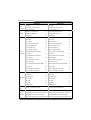
945P-A7A / 945PL-A7A Setup Manual FCC Information and Copyright This equipment has been tested and found to comply with the limits of a Class B digital device, pursuant to Part 15 of the FCC Rules. These limits are designed to provide reasonable protection against harmful interference in a residential installation. This equipment generates, uses and can radiate radio frequency energy and, if not installed and used in accordance with the instructions, may cause harmful interference to radio communications. There is no guarantee that interference will not occur in a particular installation. The vendor makes no representations or warranties with respect to the contents here and specially disclaims any implied warranties of merchantability or fitness for any purpose. Further the vendor reserves the right to revise this publication and to make changes to the contents here without obligation to notify any party beforehand. Duplication of this publication, in part or in whole, is not allowed without first obtaining the vendor’s approval in writing. The content of this user’s manual is subject to be changed without notice and we will not be responsible for any mistakes found in this user’s manual. All the brand and product names are trademarks of their respective companies. Table of Contents Chapter 1: Introduction.......................................... 1 1.1 1.2 1.3 1.4 1.5 1.6 Before You Start ................................................................................1 Package Checklist.............................................................................1 Motherboard Features......................................................................2 Rear Panel Connectors .....................................................................3 Motherboard Layout (945P-A7A) ..................................................4 Motherboard Layout (945PL-A7A)................................................5 Chapter 2: Hardware Installation............................ 6 2.1 2.2 2.3 2.4 Installing Central Processing Unit (CPU).......................................6 FAN Headers......................................................................................8 Installing System Memory ................................................................9 Connectors and Slots...................................................................................11 Chapter 3: Headers & Jumpers Setup.................... 13 3.1 3.2 How to Setup Jumpers ....................................................................13 Detail Settings..................................................................................13 TChapter 4: 4.1 4.2 4.3 4.4 Useful Help ......................... 19 Driver Installation Note .................................................................19 Award BIOS Beep Code ..................................................................20 Extra Information ...........................................................................20 Troubleshooting...............................................................................22 Chapter 5: WarpSpeeder™.................................... 23 5.1 5.2 5.3 5.4 Introduction .....................................................................................23 System Requirement .......................................................................23 Installation .......................................................................................24 WarpSpeeder™.................................................................................25 Appendencies: SPEC In Other Language............... 30 German .................................................................................................................31 France....................................................................................................................33 Italian ....................................................................................................................35 Spanish ..................................................................................................................37 Portuguese............................................................................................................39 Polish .....................................................................................................................41 RUSSIAN ................................................................................................................43 ARABIC..................................................................................................................45 JAPANESE .............................................................................................................47 945P-A7A / 945PL-A7A CHAPTER 1: INTRODUCTION 1.1 BEFORE YOU START Thank you for choosing our product. Before you start installing the motherboard, please make sure you follow the instructions below: 1.2 Prepare a dry and stable working environment with sufficient lighting. Always disconnect the computer from power outlet before operation. Before you take the motherboard out from anti-static bag, ground yourself properly by touching any safely grounded appliance, or use grounded wrist strap to remove the static charge. Avoid touching the components on motherboard or the rear side of the board unless necessary. Hold the board on the edge, do not try to bend or flex the board. Do not leave any unfastened small parts inside the case after installation. Loose parts will cause short circuits which may damage the equipment. Keep the computer from dangerous area, such as heat source, humid air and water. PACKAGE CHECKLIST z FDD Cable X 1 z HDD Cable X 1 z User’s Manual X 1 z Serial ATA Cable X 1 z Fully Setup Driver CD X 1 z Rear I/O Panel for ATX Case X 1 z USB 2.0 Cable X1 (optional) z S/PDIF Cable X 1 (optional) z Serial ATA Power Switch Cable X 1 (optional) 1 Motherboard Manual 1.3 MOTHERBOARD FEATURES 945P-A7A CPU FSB Chipset Super I/O 945PL-A7A LGA 775 LGA 775 Intel Pentium 4 / Pentium D / Celeron D Intel Pentium 4 / Pentium D / Celeron D processor up to 3.8 GHz processor up to 3.8 GHz Intel Core2Duo Processor (For Ver 8.0 only) Intel Core2Duo Processor (For Ver 8.0 only) Supports Hyper-Threading Supports Hyper-Threading Execute Disable Bit Execute Disable Bit Enhanced Intel SpeedStep Enhanced Intel SpeedStep Extended Memory 64 Technology Extended Memory 64 Technology 533 / 800 / 1066 MHz 533 / 800 MHz Intel 945P Intel 945PL Intel ICH7 Intel ICH7 ITE IT8712F ITE IT8712F H/W Monitor H/W Monitor Fan Speed Controller Fan Speed Controller ITE's "Smart Guardian" function ITE's "Smart Guardian" function DIMM Slots x 4 DIMM Slots x 2 Each DIMM supports 256/512MB & 1GB Each DIMM supports 256/512MB & 1GB Main DDR2 DDR2 Memory Max Memory Capicity 4GB Max Memory Capicity 2GB Dual Channel Mode DDR2 memory module Dual Channel Mode DDR2 memory module IDE SATA 10/100 LAN Sound Codec Slots 2 Supports DDR2 533 / 667 Supports DDR2 400 / 533 Integrated IDE Controller Integrated IDE Controller Ultra DMA 33~100 Bus Master Mode Ultra DMA 33~100 Bus Master Mode supports PIO Mode 0~4, supports PIO Mode 0~4, Integrated Serial ATA Controller Integrated Serial ATA Controller Data transfer rates up to 3.0 Gb/s. Data transfer rates up to 3.0 Gb/s. SATA Version 2.0 specification compliant. SATA Version 2.0 specification compliant. Realtek RTL 8100C Realtek RTL 8100C 10 / 100 Mb/s auto negotiation 10 / 100 Mb/s auto negotiation Half / Full duplex capability Half / Full duplex capability ALC655 ALC655 6 channels audio out 6 channels audio out AC’97 Version 2.3 AC’97 Version 2.3 PCI Express x 16 slot x1 PCI Express x 16 slot x1 945P-A7A / 945PL-A7A 945P-A7A On Board Connector Back Panel I/O 945PL-A7A PCI Express x 1 slot x2 PCI Express x 1 slot x2 PCI slot x3 PCI slot x3 Floppy connector x1 Floppy connector x1 IDE Connector x1 IDE Connector x1 SATA Connector x4 SATA Connector x4 Front Panel Connector x1 Front Panel Connector x1 Front Audio Connector x1 Front Audio Connector x1 CD-in Connector x1 CD-in Connector x1 S/PDIF out connector x1 S/PDIF out connector x1 CPU Fan header x1 CPU Fan header x1 System Fan header x1 System Fan header x1 Chassis open header (optional) x1 Chassis open header (optional) x1 Clear CMOS header x1 Clear CMOS header x1 Chassis open header x1 Chassis open header x1 USB connector x2 USB connector x2 Power Connector (24pin) x1 Power Connector (24pin) x1 Power Connector (4pin) x1 Power Connector (4pin) x1 PS/2 Keyboard x1 PS/2 Keyboard x1 PS/2 Mouse x1 PS/2 Mouse x1 Serial Port x1 Serial Port x1 Printer Port x1 Printer Port x1 LAN port x1 LAN port x1 USB Port x4 USB Port x4 Audio Jack x3 Audio Jack x3 Board Size 205 (W) x 305 (L) mm OS Support 1.4 Windows 2000 / XP 205 (W) x 305 (L) mm Windows 2000 / XP Biostar Reserves the right to add or remove Biostar Reserves the right to add or remove support for any OS with or without notice. support for any OS with or without notice. REAR PANEL CONNECTORS LAN PS/2 Mouse Parallel Line In/ Surround Line Out COM1 Mic In 1/ Base/Center COM1 PS/2 Keyboard USB x2 USB x2 3 Motherboard Manual 1.5 MOTHERBOARD LAYOUT (945P-A7A) JKBMS1 LGA775 JCOM1 COM1 CPU1 DDR2_B1 SATA3 JSFAN1 JCMOS1 SATA2 SATA4 DDR2_B2 DDR2_A1 DDR2_A2 JPRNT1 JAUDIO1 SATA1 Intel 945P JATXPWR2 JCFAN1 JRJ45USB1 JATXPWR1 JAUDIOF1 JCDIN1 PCI-Ex16 Codec PCI-Ex1_1 PCI-Ex1_2 BAT1 IDE1 Super I/O Intel ICH7 PCI1 BIOS PCI2 10/100 LAN JCI1 PCI3 IR JPANEL1 (optional) FDD1 JSPDIF_OUT1 Note: ■ represents the 1st pin. 4 945P-A7A / 945PL-A7A 1.6 MOTHERBOARD LAYOUT (945PL-A7A) JK BM S 1 LGA775 COM1 JCOM1 CPU1 JA UD IO 1 DDR2_B1 DDR2_A1 JPRNT1 Intel 945PL JATXPWR2 JCFAN1 JR J4 5U SB 1 JATXPWR1 JAUDIOF1 JCDIN1 P CI- Ex1 6 C ode c P CI- Ex1 _1 P CI- Ex1 _2 BAT1 IDE1 Super I/O Intel ICH7 PCI1 BIOS PCI2 10/100 LAN SATA1 SATA3 JSFAN1 JCMOS1 SATA2 SATA4 JCI1 PCI3 IR JPANEL1 (optional) FD D 1 JSPDIF_OUT1 Note: ■ represents the 1st pin. 5 Motherboard Manual CHAPTER 2: HARDWARE INSTALLATION 2.1 INSTALLING CENTRAL PROCESSING UNIT (CPU) Special Notice: Remove Pin Cap before installation, and make good preservation for future use. When the CPU is removed, cover the Pin Cap on the empty socket to ensure pin legs won’t be damaged. Pin-Cap Step 1: Pull the socket locking lever out from the socket and then raise the lever up to a 90-degree angle. 6 945P-A7A / 945PL-A7A Step 2: Look for the triangular cut edge on socket, and the golden dot on CPU should point forwards this triangular cut edge. The CPU will fit only in the correct orientation. Step 2-1: Step 2-2: Step 3: Hold the CPU down firmly, and then lower the lever to locked position to complete the installation. Step 4: Put the CPU Fan and heatsink assembly on the CPU and buckle it on the retention frame. Connect the CPU FAN power cable into the JCFAN1. This completes the installation. 7 Motherboard Manual 2.2 FAN HEADERS These fan headers support cooling-fans built in the computer. The fan cable and connector may be different according to the fan manufacturer. Connect the fan cable to the connector while matching the black wire to pin#1. JCFAN1: CPU Fan Header JCFAN1 4 Pin 1 2 3 1 4 Assignment Ground Power FAN RPM rate sense Smart Fan Control JSFAN1: System Fan Header Pin JSFAN1 3 1 1 2 3 Assignment Ground +12V FAN RPM rate sense Note: The JCFAN1 and JSFAN1 support 4-pin and 3-pin head connector. When connecting with wires onto connectors, please note that the red wire is the positive and should be connected to pin#2, and the black wire is Ground and should be connected to GND. 8 945P-A7A / 945PL-A7A DDR2_B1 DDR2_B2 INSTALLING SYSTEM MEMORY DDR2_A1 DDR2_A2 2.3 1. Unlock a DIMM slot by pressing the retaining clips outward. Align a DIMM on the slot such that the notch on the DIMM matches the break on the Slot. 2. Insert the DIMM vertically and firmly into the slot until the retaining chip snap back in place and the DIMM is properly seated. 9 Motherboard Manual B. Memory Capacity For 945P-A7A the maximum memory capacity is 4GB. DIMM Socket Location DDR Module DDR2_A1 256MB/512MB/1GB *1 DDR2_A2 256MB/512MB/1GB *1 DDR2_B1 256MB/512MB/1GB *1 DDR2_B2 256MB/512MB/1GB *1 Total Memory Size 945P Chipset Max memory 4GB. For 945PL-A7A the maximum memory capacity is 2GB. 10 DIMM Socket Location DDR Module DDR2_A1 256MB/512MB/1GB *1 DDR2_B1 256MB/512MB/1GB *1 Total Memory Size Max memory 2GB. 945P-A7A / 945PL-A7A 2.4 CONNECTORS AND SLOTS FDD1: Floppy Disk Connector The motherboard provides a standard floppy disk connector that supports 360K, 720K, 1.2M, 1.44M and 2.88M floppy disk types. This connector supports the provided floppy drive ribbon cables. 33 1 34 2 IDE1: Hard Disk Connectors The motherboard has a 32-bit Enhanced PCI IDE Controller that provides PIO Mode 0~4, Bus Master, and Ultra DMA 33/66/100/133 functionality. The IDE connectors can connect a master and a slave drive, so you can connect up to four hard disk drives. The first hard drive should always be connected to IDE1. IDE1 40 39 2 1 11 Motherboard Manual PCI-Ex16: PCI-Express x16 Slot - PCI-Express 1.0a compliant. Maximum theoretical realized bandwidth of 4GB/s simultaneously per direction, for an aggregate of 8GB/s totally. PCI-Ex1_1/PCI-EX1_2: PCI-Express x1 slots - PCI-Express 1.0a compliant. Data transfer bandwidth up to 250MB/s per direction; 500MB/s in total. PCI-Express supports a raw bit-rate of 2.5Gb/s on the data pins. 2X bandwidth over the traditional PCI architecture. PCI-Ex16 PCI-Ex1_1 PCI-Ex1_2 PCI1~PCI3: Peripheral Component Interconnect Slots This motherboard is equipped with 3 standard PCI slots. PCI stands for Peripheral Component Interconnect, and it is a bus standard for expansion cards. This PCI slot is designated as 32 bits. PCI1 PCI2 PCI3 12 945P-A7A / 945PL-A7A CHAPTER 3: HEADERS & JUMPERS SETUP 3.1 HOW TO SETUP JUMPERS The illustration shows how to set up jumpers. When the jumper cap is placed on pins, the jumper is “close”, if not, that means the jumper is “open”. Pin opened 3.2 Pin closed Pin1-2 closed DETAIL SETTINGS JPANEL1: Front Panel Header This 22-pin connector includes Power-on, Reset, HDD LED, Power LED, Sleep button, speaker and IrDA Connection. It allows user to connect the PC case’s front panel switch functions. SLP PWR_LED On/Off + + - 2 1 + SPK Pin 1 3 5 7 9 11 13 15 17 19 21 Assignment +5V N/A N/A Speaker HDD LED (+) HDD LED (-) Ground Reset control N/A +5V IRTX Function Speaker connector Hard drive LED Reset button IrDA Connector (optional) 22 21 RST HLED IR Header (optional) Pin 2 4 6 8 10 12 14 16 18 20 22 Assignment Sleep control Ground N/A Power LED (+) Power LED (+) Power LED (-) Power button Ground Key Ground IRRX Function Sleep button N/A Power LED Power-on button IrDA Connector (optional) 13 Motherboard Manual JATXPWR1: ATX Power Source Connector This connector allows user to connect 24-pin power connector on the ATX power supply. 13 1 24 12 Pin 1 2 3 4 5 6 7 8 9 Assignment +3.3V +3.3V Ground +5V Ground +5V Ground PW_OK Standby Voltage +5V +12V +12V 2 x 12 Detect +3.3V -12V Ground PS_ON Ground Ground Ground -5V +5V +5V +5V Ground 10 11 12 13 14 15 16 17 18 19 20 21 22 23 24 JATXPWR2: ATX Power Source Connector By connecting this connector, it will provide +12V to CPU power circuit. 1 2 14 3 4 Pin 1 2 3 4 Assignment +12V +12V Ground Ground 945P-A7A / 945PL-A7A JUSB3/JUSB4: Headers for USB 2.0 Ports at Front Panel This motherboard provides 2 USB 2.0 headers, which allows user to connect additional USB cable on the PC front panel, and also can be connected with internal USB devices, like USB card reader. JUSB3 Pin 1 2 3 4 5 6 7 8 9 10 JUSB4 2 10 1 9 Assignment +5V (fused) +5V (fused) USBUSBUSB+ USB+ Ground Ground Key NC JKBV1: Power Source Headers for PS/2 Keyboard and Mouse 3 1 3 1 Pin 1-2 close (Default) +5V for PS/2 keyboard and mouse. 3 1 Pin 2-3 close PS/2 keyboard and mouse are powered by +5V standby voltage. Note: In order to support this function “Power-on system via keyboard and mouse”, “JKBV1” jumper cap should be placed on Pin 2-3. 15 Motherboard Manual JAUDIOF1: Front Panel Audio Header This header allows user to connect the front audio output cable with the PC front panel. It will disable the output on back panel audio connectors. Pin 1 2 3 4 5 6 14 13 2 1 7 8 9 10 11 12 13 14 Assignment Mic in/center Ground Mic power/Bass Audio power Right line out/ Speaker out Right Right line out/ Speaker out Right Reserved Key Left line out/ Speaker out Left Left line out/ Speaker out Left Right line in/ Rear speaker Right Right line in/ Rear speaker Right Left line in/ Rear speaker Left Left line in/ Rear speaker Left JCDIN1: CD-ROM Audio-in Connector This connector allows user to connect the audio source from the variaty devices, like CD-ROM, DVD-ROM, PCI sound card, PCI TV turner card etc.. 4 1 16 Pin 1 2 3 4 Assignment Left Channel Input Ground Ground Right Channel Input 945P-A7A / 945PL-A7A JCMOS1: Clear CMOS Header By placing the jumper on pin2-3, it allows user to restore the BIOS safe setting and the CMOS data, please carefully follow the procedures to avoid damaging the motherboard. 3 1 Pin 1-2 Close: Normal Operation (Default). 3 3 1 1 Pin 2-3 Close: Clear CMOS data. ※ Clear CMOS Procedures: 1. 2. 3. 4. 5. Remove AC power line. Set the jumper to “Pin 2-3 close”. Wait for five seconds. Set the jumper to “Pin 1-2 close”. Power on the AC. 6. Reset your desired password or clear the CMOS data. JCI1: Chassis Open Header This connector allows system to monitor PC case open status. If the signal has been triggered, it will record to the CMOS and show the message on next boot-up. Pin 1 2 2 Assignment Case open signal Ground 1 17 Motherboard Manual JSATA1~JSATA4: Serial ATA Connectors The motherboard has a PCI to SATA Controller with 4channels SATA interface, it satisfies the SATA 2.0 spec and with transfer rate of 3GB/s. SATA1 SATA3 4 7 1 SATA2 SATA4 Pin 1 2 3 4 5 6 7 Assignment Ground TX+ TXGround RXRX+ Ground JSPDIF_OUT1: Digital Audio out Connectors This connector allows user to connect the PCI bracket SPDIF output/input header. Pin 1 2 3 3 18 1 Assignment +5V SPDIF_OUT1 Ground 945P-A7A / 945PL-A7A TCHAPTER 4.1 4: USEFUL HELP DRIVER INSTALLATION NOTE After you installed your operating system, please insert the Fully Setup Driver CD into your optical drive and install the driver for better system performance. You will see the following window after you insert the CD The setup guide will auto detect your motherboard and operating system. Note: If this window didn’t show up after you insert the Driver CD, please use file browser to locate and execute the file SETUP.EXE under your optical drive. A. Driver Installation To install the driver, please click on the Driver icon. The setup guide will list the compatible driver for your motherboard and operating system. Click on each device driver to launch the installation program. B. Software Installation To install the software, please click on the Software icon. The setup guide will list the software available for your system, click on each software title to launch the installation program. C. Manual Aside from the paperback manual, we also provide manual in the Driver CD. Click on the Manual icon to browse for available manual. Note: You will need Acrobat Reader to open the manual file. Please download the latest version of Acrobat Reader software from http://www.adobe.com/products/acrobat/readstep2.html 19 Motherboard Manual 4.2 AWARD BIOS BEEP CODE Beep Sound Meaning One long beep followed by two short beeps Video card not found or video card memory bad High-low siren sound CPU overheated System will shut down automatically One Short beep when system boot-up No error found during POST Long beeps every other second 4.3 No DRAM detected or install EXTRA INFORMATION A. BIOS Update After you fail to update BIOS or BIOS is invaded by virus, the Boot-Block function will help to restore BIOS. If the following message is shown after boot-up the system, it means the BIOS contents are corrupted. In this Case, please follow the procedure below to restore the BIOS: 1. Make a bootable floppy disk. 2. Download the Flash Utility “AWDFLASH.exe” from the Biostar website: www.biostar.com.tw 3. Confirm motherboard model and download the respectively BIOS from Biostar website. 4. Copy “AWDFLASH.exe” and respectively BIOS into floppy disk. 5. Insert the bootable disk into floppy drive and press Enter. 6. System will boot-up to DOS prompt. 7. Type “Awdflash xxxx.bf/sn/py/r” in DOS prompt. (xxxx means BIOS name.) 8. System will update BIOS automatically and restart. 9. The BIOS has been recovered and will work properly. 20 945P-A7A / 945PL-A7A B. CPU Overheated If the system shutdown automatically after power on system for seconds, that means the CPU protection function has been activated. When the CPU is over heated, the motherboard will shutdown automatically to avoid a damage of the CPU, and the system may not power on again. In this case, please double check: 1. The CPU cooler surface is placed evenly with the CPU surface. 2. CPU fan is rotated normally. 3. CPU fan speed is fulfilling with the CPU speed. After confirmed, please follow steps below to relief the CPU protection function. 1. Remove the power cord from power supply for seconds. 2. Wait for seconds. 3. Plug in the power cord and boot up the system. Or you can: 1. Clear the CMOS data. (See “Close CMOS Header: JCMOS1” section) 2. Wait for seconds. 3. Power on the system again. 21 Motherboard Manual 4.4 TROUBLESHOOTING Probable 1. 2. Solution No power to the system at all 1. Power light don’t illuminate, fan inside power supply does not turn 2. on. 3. Indicator light on keyboard does not turn on. System inoperative. Keyboard lights are on, power indicator lights are lit, and hard drive is spinning. Using even pressure on both ends of the DIMM, press down firmly until the module snaps into place. System does not boot from hard disk 1. drive, can be booted from optical drive. 2. System only boots from optical drive. 1. Hard disk can be read and applications can be used but booting from hard disk 2. is impossible. Check cable running from disk to disk controller board. Make sure both ends are securely plugged in; check the drive type in the standard CMOS setup. Backing up the hard drive is extremely important. All hard disks are capable of breaking down at any time. Back up data and applications files. Reformat the hard drive. Re-install applications and data using backup disks. Screen message says “Invalid Configuration” or “CMOS Failure.” Review system’s equipment. Make sure correct information is in setup. Cannot boot system after installing second hard drive. 1. 2. 22 Make sure power cable is securely plugged in. Replace cable. Contact technical support. Set master/slave jumpers correctly. Run SETUP program and select correct drive types. Call the drive manufacturers for compatibility with other drives. 945P-A7A / 945PL-A7A CHAPTER 5: WARPSPEEDER™ 5.1 INTRODUCTION [WarpSpeeder™], a new powerful control utility, features three user-friendly functions including Overclock Manager, Overvoltage Manager, and Hardware Monitor. With the Overclock Manager, users can easily adjust the frequency they prefer or they can get the best CPU performance with just one click. The Overvoltage Manager, on the other hand, helps to power up CPU core voltage and Memory voltage. The cool Hardware Monitor smartly indicates the temperatures, voltage and CPU fan speed as well as the chipset information. Also, in the About panel, you can get detail descriptions about BIOS model and chipsets. In addition, the frequency status of CPU, memory, AGP and PCI along with the CPU speed are synchronically shown on our main panel. Moreover, to protect users' computer systems if the setting is not appropriate when testing and results in system fail or hang, [WarpSpeeder™] technology assures the system stability by automatically rebooting the computer and then restart to a speed that is either the original system speed or a suitable one. 5.2 SYSTEM REQUIREMENT OS Support: Windows 98 SE, Windows Me, Windows 2000, Windows XP DirectX: DirectX 8.1 or above. (The Windows XP operating system includes DirectX 8.1. If you use Windows XP, you do not need to install DirectX 8.1.) 23 Motherboard Manual 5.3 INSTALLATION 1. Execute the setup execution file, and then the following dialog will pop up. Please click “Next” button and follow the default procedure to install. 2. When you see the following dialog in setup procedure, it means setup is completed. If the “Launch the WarpSpeeder Tray Utility” checkbox is checked, the Tray Icon utility and [WarpSpeeder™] utility will be automatically and immediately launched after you click “Finish” button. Usage: The following figures are just only for reference, the screen printed in this user manual will change according to your motherboard on hand. 24 945P-A7A / 945PL-A7A 5.4 1. WARPSPEEDER™ Tray Icon: Whenever the Tray Icon utility is launched, it will display a little tray icon on the right side of Windows Taskbar. This utility is responsible for conveniently invoking [WarpSpeeder™] Utility. You can use the mouse by clicking the left button in order to invoke [WarpSpeeder™] directly from the little tray icon or you can right-click the little tray icon to pop up a popup menu as following figure. The “Launch Utility” item in the popup menu has the same function as mouse left-click on tray icon and “Exit” item will close Tray Icon utility if selected. 25 Motherboard Manual 2. Main Panel If you click the tray icon, [WarpSpeeder™] utility will be invoked. Please refer to the following figure; the utility’s first window you will see is Main Panel. Main Panel contains features as follows: a. b. c. 26 Display the CPU Speed, CPU external clock, Memory clock, AGP clock, and PCI clock information. Contains About, Voltage, Overclock, and Hardware Monitor Buttons for invoking respective panels. With a user-friendly Status Animation, it can represent 3 overclock percentage stages: Man walking→overclock percentage from 100% ~ 110 % Panther running→overclock percentage from 110% ~ 120% Car racing→overclock percentage from 120% ~ above 945P-A7A / 945PL-A7A 3. Voltage Panel Click the Voltage button in Main Panel, the button will be highlighted and the Voltage Panel will slide out to up as the following figure. In this panel, you can decide to increase CPU core voltage and Memory voltage or not. The default setting is “No”. If you want to get the best performance of overclocking, we recommend you click the option “Yes”. 27 Motherboard Manual 4. Overclock Panel Click the Overclock button in Main Panel, the button will be highlighted and the Overclock Panel will slide out to left as the following figure. Overclock Panel contains the these features: a. “–3MHz button”, “-1MHz button”, “+1MHz button”, and “+3MHz button”: provide user the ability to do real-time overclock adjustment. Warning: Manually overclock is potentially dangerous, especially when the overclocking percentage is over 110 %. We strongly recommend you verify every speed you overclock by click the Verify button. Or, you can just click Auto overclock button and let [WarpSpeeder™] automatically gets the best result for you. b. 28 “Recovery Dialog button”: Pop up the following dialog. Let user select a restoring way if system need to do a fail-safe reboot. c. d. 945P-A7A / 945PL-A7A “Auto-overclock button”: User can click this button and [WarpSpeeder™] will set the best and stable performance and frequency automatically. [WarpSpeeder™] utility will execute a series of testing until system fail. Then system will do fail-safe reboot by using Watchdog function. After reboot, the [WarpSpeeder™] utility will restore to the hardware default setting or load the verified best and stable frequency according to the Recovery Dialog’s setting. “Verify button”: User can click this button and [WarpSpeeder™] will proceed a testing for current frequency. If the testing is ok, then the current frequency will be saved into system registry. If the testing fail, system will do a fail-safe rebooting. After reboot, the [WarpSpeeder™] utility will restore to the hardware default setting or load the verified best and stable frequency according to the Recovery Dialog’s setting. Note: Because the testing programs, invoked in Auto-overclock and Verify, include DirectDraw, Direct3D and DirectShow tests, the DirectX 8.1 or newer runtime library is required. And please make sure your display card’s color depth is High color (16 bit) or True color( 24/32 bit ) that is required for Direct3D rendering. 5. Hardware Monitor Panel Click the Hardware Monitor button in Main Panel, the button will be highlighted and the Hardware Monitor panel will slide out to left as the following figure. In this panel, you can get the real-time status information of your system. The information will be refreshed every 1 second. 29 Motherboard Manual 6. About Panel Click the “about” button in Main Panel, the button will be highlighted and the About Panel will slide out to up as the following figure. In this panel, you can get model name and detail information in hints of all the chipset that are related to overclocking. You can also get the mainboard’s BIOS model and the Version number of [WarpSpeeder™] utility. Note: Because the overclock, overvoltage, and hardware monitor features are controlled by several separate chipset, [WarpSpeeder™] divide these features to separate panels. If one chipset is not on board, the correlative button in Main panel will be disabled, but will not interfere other panels’ functions. This property can make [WarpSpeeder™] utility more robust.APPENDENCIES: 30 SPEC IN OTHER 945P-A7A / 945PL-A7A LANGUAGE GERMAN 945P-A7A CPU FSB Chipsatz Super E/A 945PL-A7A LGA 775 LGA 775 Intel Pentium 4 / Pentium D / Celeron D Intel Pentium 4 / Pentium D / Celeron D Prozessoren mit bis zu 3,8 GHz Prozessoren mit bis zu 3,8 GHz Intel Core2Duo Prozessoren (nur für Ver Intel Core2Duo Prozessoren (nur für Ver 8.0) 8.0) Unterstützt Hyper-Threading Unterstützt Hyper-Threading Execute Disable Bit Execute Disable Bit Enhanced Intel SpeedStep® Enhanced Intel SpeedStep® Extended Memory 64 Technology Extended Memory 64 Technology 533 / 800 / 1066 MHz 533 / 800 MHz Intel 945P Intel 945PL Intel ICH7 Intel ICH7 ITE 8712F ITE 8712F Hardware-Überwachung Hardware-Überwachung Lüfterdrehzahl-Controller Lüfterdrehzahl-Controller "Smart Guardian"-Funktion von ITE "Smart Guardian"-Funktion von ITE DDR2 DIMM-Steckplätze x 4 DDR2 DIMM-Steckplätze x 2 Jeder DIMM unterstützt 128/256/512MB & Jeder DIMM unterstützt 256/512MB & 1GB Arbeitsspeic 1GB DDR2 DDR2 her Max. 4GB Arbeitsspeicher Max. 2GB Arbeitsspeicher Dual-Kanal DDR Speichermodul Dual-Kanal DDR Speichermodul IDE SATA LAN Unterstützt DDR2 533 / 667 Unterstützt DDR2 400 / 533 Integrierter IDE-Controller Integrierter IDE-Controller Ultra DMA 33 / 66 / 100 Bus Master-Modus Ultra DMA 33 / 66 / 100 Bus Master-Modus Unterstützt PIO-Modus 0~4 Unterstützt PIO-Modus 0~4 Integrierter Serial ATA-Controller Integrierter Serial ATA-Controller Datentransferrate bis zu 3.0Gb/s Datentransferrate bis zu 3.0Gb/s Konform mit der SATA-Spezifikation Konform mit der SATA-Spezifikation Version 2.0 Version 2.0 Realtek 8100C Realtek 8100C 10 / 100 Mb/s Auto-Negotiation 10 / 100 Mb/s Auto-Negotiation Halb-/ Vollduplex-Funktion Halb-/ Vollduplex-Funktion Audio-Code ALC 655 ALC 655 31 Motherboard Manual 945P-A7A c 945PL-A7A 6-Kanal-Audioausgabe 6-Kanal-Audioausgabe AC’97 Version 2.3 PCI Express x16 Steckplatz PCI Express x16 Steckplatz x1 x2 PCI Express x1 Steckplatz x2 PCI-Steckplatz x3 PCI-Steckplatz x3 Diskettenlaufwerkanschluss x1 Diskettenlaufwerkanschluss x1 IDE-Anschluss x1 IDE-Anschluss x1 SATA-Anschluss x4 SATA-Anschluss x4 Fronttafelanschlu