1
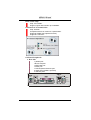
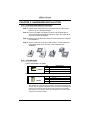
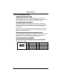
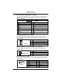
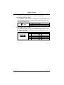
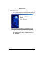
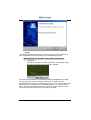
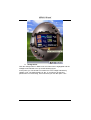
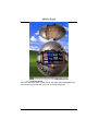
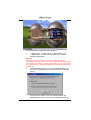
K8NHA Grand
FCC In
Information and Copyright
This equipment has been tested and found to comply with the limits of a
Class B digital device, pursuant to Part 15 of the FCC Rules. These limits are
designed to provide reasonable protection against harmful interference in a
residential installation. This equipment generates, uses and can radiate
radio frequency energy and, if not installed and used in accordance with the
instructions, may cause harmful interference to radio communications.
There is no guarantee that interference will not occur in a particular
installation.
The vendor makes no representations or warranties with respect to the
contents here and specially disclaims any implied warranties of
merchantability or fitness for any purpose. Further the vendor reserves the
right to revise this publication and to make changes to the contents here
without obligation to notify any party beforehand.
Duplication of this publication, in part or in whole, is not allowed without first
obtaining the vendor’s approval in writing.
The content of this user’s manual is subject to be changed without notice
and we will not be responsible for any mistakes found in this user’s manual.
All the brand and product names are trademarks of their respective
companies.
1
K8NHA Grand
TABLE OF CONTENTS
Chapter 1: Introduction .................................................... 3
1.1
1.2
K8NHA GRAND Features................................................3
Package Checklist ..............................................................6
1.3
1.3
Layout of K8NHA GRAND..............................................7
Components of K8NHA GRAND....................................8
Chapter 2: Hardware Installation ..................................... 9
2.1
Central Processing Unit (CPU).........................................9
2.2
2.3
Fan Headers ........................................................................9
Memory Modules Installation........................................10
2.4
Connectors, & Slots..........................................................11
Chapter 3: Headers & Jumpers Setup........................... 12
3.1
3.2
How to setup Jumpers.....................................................12
Detail Settings...................................................................12
Chapter 4: Useful Help.................................................... 17
4.1
Award BIOS Beep Code ..................................................17
4.2
Troubleshooting ...............................................................17
Chapter 5: NVIDIA RAID Function ................................. 18
5.1
5.2
Operation System.............................................................18
Raid Arrays.......................................................................18
5.3
How RAID Works............................................................19
Chapter 6: WarpSpeeder™ .................................... 23
6.1
Introduction ......................................................................23
6.2
6.3
System Requirement........................................................23
Installation ........................................................................24
2
K8NHA Grand
CHAPTER 1: INTRODUCTION
1.1
K8NHA GRAND FEATURES
A. Hardware
CPU
Supports Socket 754.
Supports the AMD Athlon 64 Socket 754 processor
Supports AMD Sempron Socket 754 processor
Chipset
NVIDIA NF3 250Gb.
- Hyper Transport link to the AMD Athlon 64 CPU.
- Supports AGP 3.0 8x interface.
- Supports system and power management.
- Supports 4 IDE disk drives, integrated RAID 0, RAID 1
and RAID 0+1 functions.
- Supports PIO Mode 5, Bride Mode and Ultra DMA
33/66/100/133 Bus Master Mode.
- Supports USB 2.0, 8 ports.
- Complaints with PCI Version 2.3 specification.
- Complaints with AC’97 Version 2.3 specification.
- Fast ATA/133 IDE controllers.
Main Memory
Supports up to 2 DDR devices.
Supports 200/266/333/400 MHz DDR devices.
Certified DDR400+ List
- Please check the website:
http://www.biostar.com.tw/products/mainboard/board.ph
p3?name=K8NHA%20Grand
Maximum memory size is 2GB.
DIMM Socket
Location
DIMM1
DIMM2
DDR Module
Total Memory
Size (MB)
128MB/256MB/512MB/1GB *1
128MB/256MB/512MB/1GB *1
Max is 2 GB.
Super I/O
Chip: ITE IT8712F.
Low Pin Count Interface.
Provides the most commonly used legacy Super I/O
functionality.
Environment Control initiatives,
- H/W Monitor
- Fan Speed Controller
- ITE's "Smart Guardian" function
3
K8NHA Grand
Slots
5 x 32-bit PCI bus master slots.
1 x AGP 8x slot
On Board IDE
Supports 2 IDE disk drives.
Supports PIO mode 4, Block Mode and Ultra DMA
33/66/100/133 bus master mode.
10/100 LAN (optional)
PHY: RTL8201BLC
Supports 10 Mb/s and 100 Mb/s auto-negotiation.
Half/Full duplex capability.
Gigabit LAN
NVIDIA Gigabit MAC + CICADA Gigabit PHY (VSC8201)
Supports 10 Mb/s, 100 Mb/s and 1Gb/s auto-negotiation.
Half/Full duplex capability.
Supports personal Firewall setup.
Supports ACPI power management.
Supports NVIDIA StreamThru technology
- Isochronous controller paired with Hyper Transport
results in fastest networking performance
Security
NVIDIA Firewall technology
Native firewall solution
Advanced features
Remote access, configuration, monitoring
Command line interface (CLI)
WMI scripts.
Serial ATA
Supports 2 serial ATA (SATA) ports.
Compliant with SATA 1.0 specification.
Data transfer rates up to 150 MB/s
Storage
NVIDIA RAID Technology
- RAID 0 disk striping for highest system and application
performance
- RAID 1 disk mirroring support for fault tolerance
Support for both SATA and ATA-133 disk controller
standards
- RAID 0+1 disk striping and mirroring for highest
performance with fault tolerance
4
K8NHA Grand
IEEE 1394A Chip
Chip: VIA VT6307.
Support 2 ports with transfer up to 400Mb/s.
On Board AC’97 Sound Codec
Chip: ALC655
Compliant with AC’97 Version 2.3 specification.
Supports S/PDIF Out (optional function).
Supports 6 channels.
On Board Peripherals
a. Rear side
1 parallel port.
1RJ-45 LAN jack.
1 IEEE1394 port.
1 Audio port.
1 PS/2 keyboard & mouse port.
2 serial ports (COM2 is optional).
4 USB 2.0 ports.
LAN
PS/2
Mouse
1394
Parallel
Line In/
Surround
Line Out
Mic In 1/
Base/Center
COM3
(optional)
COM1
PS/2
Keyboard
USB x2
USB x2
5
K8NHA Grand
b. Front Side
4 USB2.0 ports.
1 Line-in port.
1 Line-out port.
1 IEEE1394 port.
1 S/PDIF out connector
1 floppy port supports 2 FDD with 360K, 720K, 1.2M,
1.44M and 2.88Mbytes.
Dimensions
ATX Form Factor: 21.5x29.3cm (W x L)
B. BIOS & Software
BIOS
Award legal BIOS.
Supports APM1.2.
Supports ACPI.
Supports USB Function.
Software
Supports Warpspeeder™, 9th Touch™, WINFLASHER™
and FLASHER™.
Offers the highest performance for Windows 98 SE,
Windows 2000, Windows Me, Windows XP, SCO UNIX etc.
1.2
PACKAGE CHECKLIST
FDD Cable X 1
HDD Cable X 1
User’s Manual X 1
Fully Setup Driver CD X 1
Rear I/O Panel for ATX Case X 1
USB 2.0 Cable X1 (optional)
S/PDIF Cable X 1 (optional)
Serial ATA Cable X 1 (optional)
IEEE 1394 Cable X 1 (optional)
Serial ATA Power Switch Cable X 1 (optional)
6
K8NHA Grand
1.3
LAYOUT OF K8NHA GRAND
Note:
st
1.
● represents the 1 pin.
2.
*: JCOM2 and JCOM3 are optional, and only one of them can be
chosen.
7
K8NHA Grand
1.3
COMPONENTS OF K8NHA GRAND
A. JATXPWR1~2: ATX power
connectors.
B. JUSBV1: Power source for
J1394_USB1.
C. JKBMSV1: Power source for
JKBMS1.
D. Back panel connectors.
E. JAUDIO1: Audio out header.
F AGP1: Accelerated Graphics Port
slot.
G. JCDIN1: CD-ROM audio-in header
H. JSPDIF_OUT: Digital audio out
header (optional).
I. PCI1~5: Peripheral Component
Interconnect slots.
J. J1394A1: Front 1394 header.
K. J1394V1: Power source for
J1394A1.
L.
JPANEL1: Front panel connector.
M. IDE1~2: Hard disk connectors.
N. JSFAN1: System fan connector.
O. JCMOS1: Clear CMOS Header.
P. JCI1: Case open Header.
Q. JUSB1~2: Front USB headers.
R. JUSBV3: Power source for JUSB1~2.
S. JSATA4~5: Serial ATA connectors.
T.
FDD1: Floppy disk connector.
U. DDR1~2: DDR memory modules.
V. JCFAN1: CPU fan connector.
8
K8NHA Grand
CHAPTER 2: HARDWARE INSTALLATION
2.1
CENTRAL PROCESSING UNIT (CPU)
Step 1: Pull the lever sideways away from the socket and then raise
the lever up to a 90-degree angle.
Step 2: Look for the black cut edge on socket, and the white dot on
CPU should point fowards this black cut edge. The CPU will fit
only in the correct orientation.
Step 3: Hold the CPU down firmly, and then close the lever to complete
the installation.
Step 4: Put the CPU Fan on the CPU and buckle it. Connect the CPU
FAN power cable to the JCFAN1. This completes the
installation.
2.2
FAN HEADERS
CPU FAN Header: JCFAN1
Pin
1
2
3
1
JCFAN1
Assignment
Ground
+12V
FAN RPM rate sense
System Fan Header: JSFAN1
Pin
1
2
3
1
JSFAN1
Assignment
Ground
+12V
FAN RPM rate sense
Note:
The JCFAN1 and JSFAN1support system cooling fan with Smart Fan
Control utility. It supports 3 pin head connector. When connecting with
wires onto connectors, please note that the red wire is the positive
and should be connected to pin#2, and the black wire is Ground and
should be connected to GND.
9
K8NHA Grand
2.3
MEMORY MODULES INSTALLATION
2.2.1
DDR Module installation
1. Unlock a DIMM slot by pressing the retaining clips outward. Align a
DIMM on the slot such that the notch on the DIMM matches the
break on the Slot.
2. Insert the DIMM vertically and firmly into the slot until the retaining
chip snap back in place and the DIMM is properly seated.
Note:
To assure the system safety, if you need to change DDR modules,
firstly, please unplug the 20-pin power cable with the power
connector, and then you can change the modules. Afterwards,
plug in the cable the power connector again, and finally you can
boot up the system.
10
K8NHA Grand
2.4
CONNECTORS, & SLOTS
Floppy Disk Connector: FDD1
The motherboard provides a standard floppy disk connector that
supports 360K, 720K, 1.2M, 1.44M and 2.88M floppy disk types. This
connector supports the provided floppy drive ribbon cables.
Hard Disk Connectors: IDE1~2
The motherboard has a 32-bit Enhanced PCI IDE Controller that
provides PIO Mode 0~5, Bus Master, and Ultra DMA 33/66/100/133
functionality. It has two HDD connectors IDE1 (primary) and IDE2
(secondary).
The IDE connectors can connect a master and a slave drive, so you
can connect up to four hard disk drives. The first hard drive should
always be connected to IDE1.
Peripheral Component Interconnect Slots: PCI1~5
This motherboard is equipped with 1 standard PCI slot. PCI stands for
Peripheral Component Interconnect, and it is a bus standard for
expansion cards. This PCI slot is designated as 32 bits.
Serial ATA Connector: JSATA4~5
The motherboard has a SATA Controller in nForce 3 250Gb with 2
channels SATA interface, it satisfies the SATA 1.0 spec and with
transfer rate of 1.5Gb/s.
7
1
SATA4/SATA5
Pin
1
3
5
7
Assignment
Ground
TXRXGround
11
Pin
Assignment
2 TX+
4 Ground
6 RX+
K8NHA Grand
CHAPTER 3: HEADERS & JUMPERS SETUP
3.1
HOW TO SETUP JUMPERS
The illustration shows how to set up jumpers. When the jumper cap is
placed on pins, the jumper is “close”, if not, that means the jumper is
“open”.
Pin opened
3.2
Pin closed
Pin1-2 closed
DETAIL SETTINGS
Power Connectors: JATXPWR1/PATXPWR2
JATXPWR1: This connector allows user to connect 20-pin power
connector on the ATX power supply.
JATXPWR2: By connecting this connector, it will provide +12V to
CPU power circuit.
10
20
1
11
JATXPWR1
2
1
3
JATXPWR2
Pin
1
2
3
4
5
6
7
8
9
10
Assignment
+3.3V
+3.3V
Ground
+5V
Ground
+5V
Ground
PW_OK
Standby Voltage +5V
+12V
Pin
Assignment
1 +12V
2 +12v
12
Pin
11
12
13
14
15
16
17
18
19
20
Assignment
+3.3V
-12V
Ground
PS_ON
Ground
Ground
Ground
-5V
+5V
+5V
Pin
Assignment
3 Ground
4 Ground
K8NHA Grand
Power Source Selection for USB: JUSBV1/JUSBV3
JUSBV1/JUSBV3
Assignment
3
+5V
1
Pin 1-2 close
3
+5V standby
Voltage
1
Pin 2-3 close
Description
JUSBV1: +5V for USB at the
J1394_USB1 and JUSBLAN1
connector ports.
JUSBV3: +5V for USB at the JUSB
1~2 connector ports.
JUSBV1: J1394_USB1 and
JUSBLAN1 ports powered with
standby voltage of +5V
JUSBV3: JUSB1~2 ports powered
with standby voltage of 55V
Note:
In order to support this function “Power-on system via USB device,”
“JUSBV1/JUSBV3” jumper cap should be placed on Pin 2-3
individually.
Power Source Selection for Keyboard/Mouse: JKBMSV1
JKBMSV1
Assignment
Description
3
+5V
1
3
1
+5V for keyboard and mouse
Pin 1-2 close
Pin 2-3 close
PS/2 mouse and PS/2 keyboard
+5V Standby
are powered with +5V standby
Voltage
voltage.
Note:
In order to support this function “Power-on system via keyboard and
mouse”, “JKBMSV1” jumper cap should be placed on Pin 2-3.
COM2 Header: JCOM2 (Optional)
This header allows user to connect additional serial cable on the PC
back panel. It can be used to connect serial devices, for example,
mouse or modem.
2
1
Pin
1
3
5
7
9
10
9
Assignment
RIN1
DOUT2
Ground
DOUT1
-XRI1
13
JCOM2-Header
Pin
Assignment
2
RIN3
4
DOUT3
6
RIN2
8
RIN4
10
NA
K8NHA Grand
Front Panel Audio Out Header: JAUDIO1
This connector will allow user to connect with the front audio out put
headers on the PC case. It will disable the output on back panel
audio connectors.
14
13
2
1
Pin
Assignment
1 Mic in/center
3 Mic power/Bass
Right line out/Speaker out
5
Right
7 Reserved
9 Left line out/Speaker out Left
Right line in/Rear speaker
11
Right
13 Left line in/Rear speaker Left
JAUDIO1
Pin
Assignment
2 Ground
4 Audio power
6 Right line out/Speaker out Right
8 Key
10 Left line out/Speaker out Left
12 Right line in/Rear speaker Right
14 Left line in/Rear speaker Left
CD-ROM Audio-in Header: JCDIN1
This connector allows user to connect the audio source from the
veriaty devices, like CD-ROM, DVD-ROM, PCI sound card, PCI TV
turner card etc..
Pin
1
2
3
4
1
JCDIN1
Assignment
Left channel input
Ground
Ground
Right channel input
Digital Audio Out Connector: JSPDIF_OUT (optional)
This connector will allow user to connect the PCI bracket SPDIF
output header.
1
Pin
1
2
3
JSPDIF_OUT
Assignment
+5V
SPDIF OUT
Ground
Front 1394 Header: J1394A1
This connector allows user to connect the front 1394 port for digital
image devices.
10
9
2
1
J1394A1
Pin
1
3
5
7
9
Assignment
A+
Ground
B+
+12v
Key
14
Pin
2
4
6
8
10
Assignment
AGround
B+12V
Ground
K8NHA Grand
Power Source for 1394: J1394V1
J1394V1
Assignment
3
1
Pin 1-2 close
3
1
Pin 2-3 close
Description
+3.3V SB
+3.3V SB for 1394 chipset.
+3.3V
+3.3V for 1394 chipset.
(Default)
Front Panel Connector: JPANEL1
This 24-pin connector includes Power-on, Reset, HDD LED, Power
LED, Sleep button, speaker and IrDA Connection. It allows user to
connect the PC case’s front panel switch functions.
2
1
Pin
1
3
5
7
9
11
13
15
17
19
21
23
Assignment
+5V
N/A
N/A
Speaker
HDD LED (+)
HEE LED (-)
Ground
Reset control
N/A
N/A
+5V
IRTX
Function
Pin
2
4
6
8
10
12
14
16
18
20
22
24
Speaker
Connector
Hard drive
LED
Reset button
IrDA
Connector
24
23
JPANEL1
Assignment
Function
Sleep control
Sleep button
Ground
N/A
N/A
Power LED (+)
Power LED (+) Power LED
Power LED (-)
Power button
Power-on button
Ground
Key
Key
IrDA Connector
Ground
IRRX
Close CMOS Jumper: JCMOS1
By placing the jumper on pin2-3, it allows user to restore the BIOS
safe setting and the CMOS data, please carefully follow the
procedures to avoid damaging the motherboard.
JCMOS1
Assignment
3
Normal Operation (Default).
1
Pin 1-2 close
3
Clear CMOS data.
1
Pin 2-3 close
※ Clear CMOS Procedures:
1.
2.
3.
4.
Remove AC power line.
Set the jumper to “Pin 2-3 close”.
Wait for five seconds.
Set the jumper to “Pin 1-2 close”.
15
K8NHA Grand
5. Power on the AC.
6. Reset your desired password or clear the CMOS data.
Case Open Connector: JCI1
This connector allows system to monitor PC case open status. If the
signal has been triggered, it will record to the CMOS and show the
message on next boot-up.
1
JCI1
Pin
1
2
Assignment
Case open signal
Ground
Front USB Header: JUSB1~2
This connector allows user to connect additional USB cables on the
PC front panel. Also can be connected with internal USB devices,
like USB card reader.
1
10
2
JUSB1/JUSB2
Pin
1
3
5
7
9
Assignment
+5V (fused)
USBUSB+
Ground
Key
16
Pin
2
4
6
8
10
Assignment
+5V (fused)
USBUSB+
Ground
NC
K8NHA Grand
CHAPTER 4: USEFUL HELP
4.1
AWARD BIOS BEEP CODE
Beep Sound
Meaning
One long beep followed by two short Video card not found or video card
beeps
memory bad
High-low siren sound
CPU overheated
System will shut down automatically
One Short beep when system
No error found during POST
boot-up
Long beeps every other second
No DRAM detected or install
4.2
TROUBLESHOOTING
Probable
No power to the system at all
Power light don’t illuminate, fan
inside power supply does not
turn on.
2. Indicator light on keyboard does
not turn on.
System inoperative. Keyboard lights
are on, power indicator lights are lit,
and hard drive is spinning.
System does not boot from hard disk
drive, can be booted from optical
drive.
1.
1.
2.
3.
Solution
Make sure power cable is
securely plugged in.
Replace cable.
Contact technical support.
Using even pressure on both ends of
the DIMM, press down firmly until the
module snaps into place.
1. Check cable running from disk to
disk controller board. Make sure
both ends are securely plugged
in; check the drive type in the
standard CMOS setup.
2. Backing up the hard drive is
extremely important. All hard
disks are capable of breaking
down at any time.
System only boots from optical drive. Back up data and applications files.
Hard disk can be read and
Reformat the hard drive. Re-install
applications can be used but booting applications and data using backup
from hard disk is impossible.
disks.
Screen message says “Invalid
Review system’s equipment. Make
Configuration” or “CMOS Failure.”
sure correct information is in setup.
Cannot boot system after installing
Set master/slave jumpers correctly.
second hard drive.
Run SETUP program and select
correct drive types. Call the drive
manufacturers for compatibility with
other drives.
17
K8NHA Grand
CHAPTER 5: NVIDIA RAID FUNCTION
5.1
OPERATION SYSTEM
Windows XP home Edition
Windows XP Professional Edition
Windows 2000 Professional
5.2
RAID ARRAYS
NVRAID supports the following types of RAID arrays:
RAID 0:
RAID 0 defines a disk striping scheme that improves disk read and writes
times for many applications.
RAID 1:
RAID 1 defines techniques for mirroring data.
RAID 0+1:
RAID 0+1 combines the techniques used in RAID 0 and RAID 1.
Spanning (JBOD):
JBOD provides a method for combining drives of different sizes in to one
large disk.
18
K8NHA Grand
5.3
HOW RAID WORKS
RAID 0:
The controller “stripes” data across multiple drives in a RAID 0 array
system. It breaks up a large file into smaller blocks and performs disk
reads and writes across multiple drives in parallel. The size of each
block is determined by the strip size parameter, which you set during
the creation of the RAID set based on the system environment.
This technique reduces overall disk access time and offers high
bandwidth.
Features and Benefits
Drives: Minimum 1, and maximum is up to 6 or 8.
Depending on the platform.
Uses: Intended for non-critical data requiring high data
throughput, or any environment that does not require fault
tolerance.
Benefits: provides increased data throughput, especially for
large files. No capacity loss penalty for parity.
Drawbacks: Does not deliver any fault tolerance. If any drive
in the array fails, all data is lost.
Fault Tolerance: No.
19
K8NHA Grand
RAID 1:
Every read and write is actually carried out in parallel across 2 disk
drives in a RAID 1 array system. The mirrored (backup) copy of the
data can reside on the same disk or on a second redundant drive in the
array. RAID 1 provides a hot-standby copy of data if the active
volume or drive is corrupted or becomes unavailable because of a
hardware failure.
RAID techniques can be applied for high-availability solutions, or as a
form of automatic backup that eliminates tedious manual backups to
more expensive and less reliable media.
Features and Benefits
Drives: Minimum 2, and maximum is 2.
Uses: RAID 1 is ideal for small databases or any other
application that requires fault tolerance and minimal capacity.
Benefits: Provides 100% data redundancy. Should one drive
fail, the controller switches to the other drive.
Drawbacks: Requires 2 drives for the storage space of one
drive. Performance is impaired during drive rebuilds.
Fault Tolerance: Yes.
20
K8NHA Grand
RAID 0+1:
RAID 0 drives can be mirrored suing RAID 1 techniques. Resulting in
a RAID 0+1 solution for improved performance plus resiliency.
Features and Benefits
Drives: Minimum 4, and maximum is 6 or 8, depending on
the platform.
Benefits: Optimizes for both fault tolerance and
performance, allowing for automatic redundancy. May be
simultaneously used with other RAID levels in an array, and
allows for spare disks.
Drawbacks: Requires twice the available disk space for data
redundancy, the same as RAID level 1.
Fault Tolerance: Yes.
21
K8NHA Grand
Spanning (JBOD):
JBOD stands for “Just a Bunch of Disks”. Each drive is accessed as if
it were on a standard SCSI host bus adapter. This is useful when a
single drive configuration is needed, but it offers no speed
improvement or fault tolerance.
Features and Benefits
Uses: JBOD works best if you have odd sized drives and
you want to combine them to make one big drive.
Benefits: JBOD provides the ability to combine odd size
drives using all of the capacity of the drives.
Drawbacks: Decreases performance because of the
difficulty in using drives concurrently.
Fault Tolerance: Yes.
※ For more detailed setup information, please refer to the Driver
CD.
22
K8NHA Grand
CHAPTER 6: WARPSPEEDER™
6.1
INTRODUCTION
[WarpSpeeder™], a new powerful control utility, features three
user-friendly functions including Overclock Manager, Overvoltage
Manager, and Hardware Monitor.
With the Overclock Manager, users can easily adjust the frequency they
prefer or they can get the best CPU performance with just one click. The
Overvoltage Manager, on the other hand, helps to power up CPU core
voltage and Memory voltage. The cool Hardware Monitor smartly
indicates the temperatures, voltage and CPU fan speed as well as the
chipset information. Also, in the About panel, you can get detail
descriptions about BIOS model and chipsets. In addition, the frequency
status of CPU, memory, AGP and PCI along with the CPU speed are
synchronically shown on our main panel.
Moreover, to protect users' computer systems if the setting is not
appropriate when testing and results in system fail or hang,
[WarpSpeeder™] technology assures the system stability by
automatically rebooting the computer and then restart to a speed that is
either the original system speed or a suitable one.
6.2
SYSTEM REQUIREMENT
OS Support: Windows 98 SE, Windows Me, Windows 2000, Windows XP
DirectX: DirectX 8.1 or above. (The Windows XP operating system
includes DirectX 8.1. If you use Windows XP, you do not need to install
DirectX 8.1.)
23
K8NHA Grand
6.3
INSTALLATION
1. Execute the setup execution file, and then the following dialog will
pop up. Please click “Next” button and follow the default procedure
to install.
2. When you see the following dialog in setup procedure, it means
setup is completed. If the “Launch the WarpSpeeder Tray Utility”
checkbox is checked, the Tray Icon utility and [WarpSpeeder™]
utility will be automatically and immediately launched after you
click “Finish” button.
24
K8NHA Grand
Usage:
The following figures are just only for reference, the screen printed in this
user manual will change according to your motherboard on hand.
[WarpSpeeder™] includes 1 tray icon and 5 panels:
1.
Tray Icon:
Whenever the Tray Icon utility is launched, it will display a little
tray icon on the right side of Windows Taskbar.
This utility is responsible for conveniently invoking [WarpSpeeder™] Utility.
You can use the mouse by clicking the left button in order to invoke
[WarpSpeeder™] directly from the little tray icon or you can right-click the little
tray icon to pop up a popup menu as following figure. The “Launch Utility”
item in the popup menu has the same function as mouse left-click on tray
icon and “Exit” item will close Tray Icon utility if selected.
25
K8NHA Grand
2.
Main Panel
If you click the tray icon, [WarpSpeeder™] utility will be invoked.
Please refer to the following figure; the utility’s first window you
will see is Main Panel.
Main Panel contains features as follows:
a.
b.
c.
Display the CPU Speed, CPU external clock, Memory clock,
AGP clock, and PCI clock information.
Contains About, Voltage, Overclock, and Hardware Monitor
Buttons for invoking respective panels.
With a user-friendly Status Animation, it can represent 3
overclock percentage stages:
Man walking→overclock percentage from 100% ~ 110 %
Panther running→overclock percentage from 110% ~ 120%
Car racing→overclock percentage from 120% ~ above
26
K8NHA Grand
3. Voltage Panel
Click the Voltage button in Main Panel, the button will be highlighted and the
Voltage Panel will slide out to up as the following figure.
In this panel, you can decide to increase CPU core voltage and Memory
voltage or not. The default setting is “No”. If you want to get the best
performance of overclocking, we recommend you click the option “Yes”.
27
K8NHA Grand
4. Overclock Panel
Click the Overclock button in Main Panel, the button will be highlighted and
the Overclock Panel will slide out to left as the following figure.
28
K8NHA Grand
Overclock Panel contains the these features:
a.
“–3MHz button”, “-1MHz button”, “+1MHz button”, and
“+3MHz button”: provide user the ability to do real-time
overclock adjustment.
Warning:
Manually overclock is potentially dangerous, especially when the
overclocking percentage is over 110 %. We strongly recommend you verify
every speed you overclock by click the Verify button. Or, you can just click
Auto overclock button and let [WarpSpeeder™] automatically gets the best
result for you.
b.
“Recovery Dialog button”: Pop up the following dialog. Let
user select a restoring way if system need to do a fail-safe
reboot.
c.
“Auto-overclock button”: User can click this button and
[WarpSpeeder™] will set the best and stable performance
29
K8NHA Grand
d.
and frequency automatically. [WarpSpeeder™] utility will
execute a series of testing until system fail. Then system will
do fail-safe reboot by using Watchdog function. After reboot,
the [WarpSpeeder™] utility will restore to the hardware
default setting or load the verified best and stable frequency
according to the Recovery Dialog’s setting.
“Verify button”: User can click this button and
[WarpSpeeder™] will proceed a testing for current frequency.
If the testing is ok, then the current frequency will be saved
into system registry. If the testing fail, system will do a
fail-safe rebooting. After reboot, the [WarpSpeeder™] utility
will restore to the hardware default setting or load the verified
best and stable frequency according to the Recovery
Dialog’s setting.
Note:
Because the testing programs, invoked in Auto-overclock and Verify,
include DirectDraw, Direct3D and DirectShow tests, the DirectX 8.1
or newer runtime library is required. And please make sure your
display card’s color depth is High color (16 bit) or True color( 24/32
bit ) that is required for Direct3D rendering.
5.
Hardware Monitor Panel
Click the Hardware Monitor button in Main Panel, the button will
be highlighted and the Hardware Monitor panel will slide out to
left as the following figure.
In this panel, you can get the real-time status information of your
system. The information will be refreshed every 1 second.
6.
About Panel
Click the “about” button in Main Panel, the button will be
highlighted and the About Panel will slide out to up as the
30
K8NHA Grand
following figure.
In this panel, you can get model name and detail information in
hints of all the chipset that are related to overclocking. You can
also get the mainboard’s BIOS model and the Version number of
[WarpSpeeder™] utility.
Note:
Because the overclock, overvoltage, and hardware monitor features
are controlled by several separate chipset, [WarpSpeeder™] divide
these features to separate panels. If one chipset is not on board, the
correlative button in Main panel will be disabled, but will not interfere
other panels’ functions. This property can make [WarpSpeeder™]
utility more robust.
31
K8NHA Grand
07/30, 2004
32