1
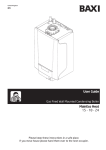
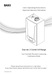
United Kingdom
en
User Guide
Gas Fired Wall Mounted Condensing System Boiler
EcoBlue System
12 - 15 - 18 - 24 - 28 - 32
Please keep these instructions in a safe place.
If you move house, please hand them over to the next occupier.
Model Range
Baxi EcoBlue 12 System
G.C.No 47-077-95
Baxi EcoBlue 15 System
G.C.No 47-077-96
Baxi EcoBlue 18 System
G.C.No 47-077-97
Baxi EcoBlue 24 System
G.C.No 47-077-98
Baxi EcoBlue 28 System
G.C.No 47-077-99
Baxi EcoBlue 32 System
G.C.No 47-470-01
Most illustrations in this document
show the 12/15/18/24/28 models.
Where the detail for 32 model differs it
is described in the text or shown in a
specific diagram.
Dear Customer,
Thank you for purchasing this appliance.
Please read this manual carefully before using the product and keep it in a safe place for future reference.
In order to ensure continued safe and efficient operation we recommend that the product is regularly maintained. Our Service and
After Sales organization can assist with this.
We hope you will receive many years of satisfactory service.
0086
© Baxi Heating UK Ltd 2014 All rights reserved. No part of this
publication may be reproduced or transmitted in any form or by any
means, or stored in any retrieval system of any nature (including in any
database), in each case whether electronic, mechanical, recording or
otherwise, without the prior written permission of the copyright owner,
except for permitted fair dealing under Copyrights, Designs and
Patents Act 1988.
Applications for the copyright owner’s permission to reproduce or
make other use of any part of this publication should be made, giving
details of the proposed use, to the following address:
The Company Secretary, Baxi Heating UK Limited,
Brooks House, Coventry Road, Warwick. CV34 4LL
Full acknowledgement of author and source must be given.
WARNING: Any person who does any unauthorised act in relation to a
copyright work may be liable to criminal prosecution and civil claims for
damages.
The Benchmark Scheme
Baxi Heating UK Ltd is a licensed member of the Benchmark Scheme
which aims to improve the standards of installation and commissioning
of domestic heating and hot water systems in the UK and to encourage
regular servicing to optimise safety, efficiency and performance.
Benchmark is managed and promoted by Heating and Hotwater
Industry Council. For more information visit www.centralheating.co.uk
2
EcoBlue System
7212141-02 (06/14)
Contents
Contents
1
2
Introduction
5
1.1
1.2
1.3
1.4
1.5
5
5
5
6
6
6
7
7
Safety
2.1
2.2
3
4
6
7
8
General Safety Instructions
Recommendations
2.2.1
Benchmark Commissioning Checklist
8
9
9
Technical Specifications
10
3.1
Technical Data
10
Description of the Product
12
4.1
4.2
12
12
12
13
14
14
14
4.3
4.4
4.5
5
General
Additional Documentation
Symbols Used
Abbreviations / Glossary
Liabilities
1.5.1
Manufacturer’s Liability
1.5.2
Installer’s Responsibility
1.5.3
User’s Responsibility
General Description
Operating Principle
4.2.1
In Operation
Control Panel Description
Standard Delivery
Accessories & Options
4.5.1
Optional Extras
Operation
15
5.1
5.2
5.3
15
15
16
Shutdown
Frost Protection
Operation Checking Procedure & Basic Fault Identification
Settings
18
6.1
18
18
18
18
18
Setting the Boiler Temperature
6.1.1
Boiler Flow Temperature
6.1.2
Inactive Buttons
6.1.3
On/Off Selector Button
6.1.4
Information Display
Maintenance
19
7.1
7.2
7.3
7.4
7.5
19
19
19
20
21
22
7212141-02 (06/14)
General
Maintenance Instructions
Repressurising the System
Venting the System
Draining the System
EcoBlue System
3
Contents
8
9
10
11
12
4
Troubleshooting
23
8.1
8.2
23
24
Error Codes
Fault Finding
Decommissioning
25
9.1
25
Decommissioning Procedure
Disposal
25
10.1
25
Disposal / Recycling
Environmental
26
11.1
26
Energy Saving
Warranty
27
12.1
12.2
27
27
27
General
Terms of Warranty
12.2.1 Standard Warranty Terms and Conditions
EcoBlue System
7212141-02 (06/14)
1
Introduction
1
Introduction
1.1
General
WARNING
Installation, repair and maintenance must only be
carried out only by a competent person. This
document is intended for use by competent persons,
All Gas Safe registered engineers carry an ID card with their
licence number and a photograph. You can check your engineer
is registered by telephoning 0800 408 5500 or online at
www.gassaferegister.co.uk
This manual is intended for the user of the Baxi EcoBlue System
boiler. If the appliance is sold or transferred, or if the owner
moves leaving the appliance behind you should ensure that the
manual is kept with the appliance for consultation by the new
owner and their installer.
The appliance is designed as a boiler for use in residential
domestic environments on a governed meter supply only. The
selection of this boiler is entirely at the owner’s risk. If the
appliance is used for purposes other than or in excess of these
specifications, the manufacturer will not accept any liability for
resulting loss, damage or injury.
1.2
Additional Documentation
The manufacturer will not accept any liability whatsoever
for loss, damage or injury arising as a result of failure to
observe the instructions for use, maintenance and
installation of the appliance.
Various timers, external controls, etc. are available as optional
extras. Full details are contained in the relevant sales literature.
1.3
Symbols Used
In these instructions, various danger levels are employed to
draw the user's attention to particular information. In so doing,
we wish to safeguard the user's safety, prevent hazards and
guarantee correct operation of the appliance.
DANGER
Risk of a dangerous situation causing serious
physical injury.
WARNING
Risk of a dangerous situation causing slight physical
injury.
CAUTION
Risk of material damage.
Signals important information .
Signals a referral to other instructions or other pages
in the instructions.
7212141-02 (06/14)
EcoBlue System
5
Introduction
1.4
1
Abbreviations / Glossary
DHW: Domestic hot water
CH: Central heating
GB: Great Britain
IE: Ireland
BS: British standard
HHIC: Heating and Hotwater Industry Council
1.5
Extent of Liabilities
1.5.1.
Manufacturer's Liability
Our products are manufactured in compliance with the
requirements of the various european applicable Directives.
They are therefore delivered with
marking and all relevant
documentation. In the interest of customers, we are
continuously endeavouring to make improvements in product
quality. All the specifications stated in this document are
therefore subject to change without notice.
The manufacturer will not accept any liability for loss, damage or
injury arising as a result of:Failure to abide by the instructions on using the appliance.
Failure to regularly maintain the appliance, or faulty or
inadequate maintenance of the appliance.
Failure to abide by the instructions on installing the
appliance.
This company declares that no substances harmful to
health are contained in the appliance or used during
appliance manufacture.
The appliance is suitable only for installation in GB and IE and
should be installed in accordance with the rules in force, and
only used in a suitably ventilated location.
In GB, the installation must be carried out by a Gas Safe
Registered Installer. It must be carried out in accordance with
the current and relevant requirements of legislation and
guidance.
Where no specific instructions are given, reference should be
made to the relevant British Standard Code of Practice.
In IE, the installation must be carried out by a competent Person
and installed in accordance with the current edition of I.S. 813
‘Domestic Gas Installations’, the current Building Regulations
and reference should be made to the current ETCI rules for
electrical installation.
Incorrect installation could invalidate the warranty and may lead
to prosecution.
6
EcoBlue System
7212141-02 (06/14)
1
Introduction
1.5.2
Installer's Responsibility
The installer is responsible for the installation and initial start up
of the appliance. The installer must adhere to the following
instructions:
Read and follow the instructions given in the manuals
provided with the appliance.
Carry out installation in compliance with the prevailing
legislation and standards.
Ensure the system is flushed and inhibitor added.
Install the flue/chimney system correctly ensuring it is
operational and complies with prevailing legislation and
standards, regardless of location of the boiler’s installation.
Only the installer should perform the initial start up and carry
out any checks necessary.
Explain the installation to the user.
Complete the Benchmark Commissioning Checklist - this is a
condition of the warranty !
Warn the user of the obligation to check the appliance and
maintain it in good working order.
Give all the instruction manuals to the user.
1.5.3.
User's Responsibility
To guarantee optimum operation of the installation, you must
observe the following instructions:
Read and observe the instructions given in the manuals
supplied with the appliance.
Seek the assistance of a qualified installer for the installation
and initial commissioning.
Ask the installer to explain the installation.
Have the required annual inspection and maintenance
carried out by a qualified installer and ensure the Benchmark
Service Record in the Installation Manual is completed - this
is a condition of the warranty !
Keep the manuals in good condition and near to the
appliance.
This appliance must not be used by people with a lack of
experience or knowledge, unless they are supervised by
someone familiar with the appliance or if they have been
instructed on how to operate the appliance correctly. Do not
allow children to operate or play with the appliance.
7212141-02 (06/14)
EcoBlue System
7
Safety
2
Safety
2.1
General Safety Instructions
2
DANGER
If you smell gas:
1. Turn off the gas supply at the meter
2. Open windows and doors in the hazardous area
3. Do not operate light switches
4. Do not operate any electrical equipment
5. Do not use a telephone in the hazardous area
6. Extinguish any naked flame and do not smoke
7. Warn any other occupants and vacate the
premises
8. Telephone the National Gas Emergency Service
on:- 0800 111 999
Water
If a water or gas leak occurs or is suspected, the boiler
can be isolated at the inlet valves by turning their taps
through 90° (1/4 turn) downwards
ON
For advice please contact your Installer, Annual
Service Provider or heateam - The Service Division of
Baxi. You can contact heateam on telephone number
0844 871 1525.
OFF
Gas
Water
When contacting heateam it will be useful to have the
‘benchmark’ checklist at the back of the Installation &
Service Manual to hand as it includes details relevant
to the boiler and installation.
WARNING
Do not touch flue/chimney pipes. Depending on the
settings of the appliance, the temperature of
flue/chimney pipes may exceed 60 °C.
Do not touch radiators for long periods. Depending on
the settings of the appliance, the temperature of
radiators may reach 85 °C.
Take precautions with domestic hot water. Depending
on the settings of the appliance, domestic hot water
temperature may reach 65 °C.
CAUTION
Do not neglect to service the appliance. Contact a
qualified professional or take out a maintenance
contract for the annual servicing of the appliance.
8
EcoBlue System
7212141-02 (06/14)
2
Safety
2.2
Recommendations
CAUTION
Only qualified professionals are authorised to work
on the appliance and the installation.
The appliance has an integral frost protection mode
as long as there is power to the boiler.
Regularly check the water pressure in the system
(recommended pressure is 1.5 bar).
See section 7.4.
Keep the appliance accessible at all times.
Do not remove or cover the user information and
serial number labels affixed to the boiler control flap.
They must remain legible throughout the
lifetime of the appliance
2.2.1
Benchmark Commissioning Checklist
1. Please ensure that the installer has fully completed the
Benchmark Checklist on the inside back pages of the installation
instructions supplied with the product and that you have signed it
to say that you have received a full and clear explanation of its
operation. The installer is legally required to complete a
commissioning checklist as a means of complying with the
appropriate Building Regulations (England and Wales).
2. All installations must be notified, by the installer, to Local Area
Building Control either directly or through a Competent Persons
Scheme. A Building Regulations Compliance Certificate will then
be issued to the customer who should, on receipt, write the
Notification Number on the Benchmark Checklist.
3. This product should be serviced annually to optimise its
safety, efficiency and performance. The service engineer should
complete the relevant section of the Benchmark Service Record
in the Installation & Service manual after each service.
4. The completed Benchmark Checklist & proof of annual
servicing (where applicable) will be required in the event of any
warranty work.
7212141-02 (06/14)
EcoBlue System
9
Technical Specifications
3
Technical Specifications
3.1
Technical Data 12/15/18/24/28
Central Heating Primary Circuit
Pressures
Safety Discharge
Max Operating
Min Operating
Recommended Operating Range
bar
3
2.5
0.5
1-2
Electrical Supply
230V~ 50Hz
(Appliance must be connected to an
earthed supply)
Electrical Protection
IPX5D (without integral timer)
IP20 (with integral timer)
External Fuse Rating
Temperatures
Boiler Flow Temp (adjustable)
25°C to 80°C max (± 5°C)
3A
NOTE: All data in this section are nominal
values and subject to normal production
tolerances.
Dimensions & Clearances These must be maintained in the event of
any alteration in the property, e.g. additional cupboards etc.
5mm Min
390mm
5mm Min
175mm Min (300mm
Min if using 80/125mm
flueing system)
450mm Min
700mm
For Servicing
Purposes &
Operating the
Controls
5mm Min In
Operation
295mm
150mm* Min *This is MINIMUM
recommended dimension.
Greater clearance will aid
installation and maintenance.
10
EcoBlue System
7212141-02 (06/14)
3
Technical Specifications
3
Technical Specifications
3.1
Technical Data 32
Central Heating Primary Circuit
Pressures
Safety Discharge
Max Operating
Min Operating
Recommended Operating Range
bar
3
2.5
0.5
1-2
Electrical Supply
230V~ 50Hz
(Appliance must be connected to an
earthed supply)
Electrical Protection
IPX5D (without integral timer)
IPX20 (with integral timer)
External Fuse Rating
Temperatures
Boiler Flow Temp (adjustable)
25°C to 80°C max (± 5°C)
3
3A
NOTE: All data in this section are nominal
values and subject to normal production
tolerances.
Dimensions & Clearances These must be maintained in the event of
any alteration in the property, e.g. additional cupboards etc.
5mm Min
450mm
5mm Min
175mm Min (300mm
Min if using 80/125mm
flueing system)
450mm Min
763mm
For Servicing
Purposes &
Operating the
Controls
5mm Min In
Operation
150mm* Min
345mm
*This is MINIMUM
recommended dimension.
Greater clearance will aid
installation and maintenance.
7212141-02 (06/14)
EcoBlue System
11
4
Description of the Product
4
Description of the Product
4.1
General Description
1. The Baxi EcoBlue System boilers are fully automatic gas fired
wall mounted condensing boilers. They are room sealed and fan
assisted, and will serve central heating and stored domestic hot
water.
2. The boiler is set to give a maximum output of :12 model 15 model 18 model -
Serial Number
Label
24 model 28 model -
User Label
32 model -
12 kW
12.7 kW (Condensing)
15 kW
15.9 kW (Condensing)
18 kW
19 kW (Condensing)
24 kW
25.4 kW (Condensing)
28 kW
29.6 kW (Condensing)
32 kW
33.8 kW (Condensing)
3. The boiler is factory set for use only on Natural Gas (G20).
Boiler Control
Flap
Fig. 1
4. The boiler model, serial number and Gas Council number are
also shown on the information label behind the boiler control flap
(Fig. 1). This is for user reference.
The boiler is set by use of the
Section 6.1.
4.2
button - see
Operating Principle
4.2.1
In Operation
1. Whilst the boiler is in operation cooled flue gases are
discharged through the flue gas discharge pipe. This may
appear as a cloud of steam which is normal.
2. Condensed water is discharged from the boiler heat
exchanger into a pipe (the condensate drain). This pipe must
never be altered or re-routed except by a qualified professional.
12
EcoBlue System
7212141-02 (06/14)
Description of the Product
4.3
4
Control Panel Description
Key to Controls
R
Standby - Reset - Esc
Boiler Information View
Standby - Reset - Esc Button
Boiler Information View Button
Increase CH Temperature Button
R
/P
/R
+
Decrease CH Temperature Button
+
Inactive Button
Inactive Button
THESE BUTTONS
INACTIVE !
except when an
outdoor sensor relay
kit is connected
Except when an
outdoor sensor relay
kit is connected
On/Off Selector Button
Boiler Flow
Temperature Adjustment
When
is displayed (Boiler On) the boiler will respond
to timed Heating or Hot Water demand.
On/Off Selector Button
N.B. If only
is displayed the boiler will not operate !
Display Description
DHW and CH OFF (frost protection still enabled)
See Section 5.2 for information
R
Indicates an error that prevents burner from igniting
Error - Not resettable by user
Water pressure too low
R
Indicates an error resettable by the user
Generic error
Burner lit
DHW mode (symbol will flash with demand)
Heating mode (symbol will flash with demand)
Units for temperature
Display showing all available characters
7212141-02 (06/14)
Units for pressure
EcoBlue System
13
4
Description of the Product
4.4
Standard Delivery
1. The literature pack contains:
Literature pack
• Installation & Servicing Manual
• User Guide Instructions
• Registration Card
• Envelope
• Fernox Leaflet
• Wall Template
4.5
Accessories & Options
4.5.1
Optional Extras
1. Various timers, external controls, etc. are available as optional
extras.
Outdoor Sensor - Wired
Mechanical Thermostat
Mechanical Timer (24 hr) - Plug-in
Digital Timer (7 day) - Plug-in
Single Channel Timer - Wired
Two Channel Timer - Wired
RF Digital Programmable Room Unit - Wireless
RF Mechanical Programmable Room Unit - Wireless
Condensate Discharge Pump and Pipe ‘Trace Heating’
Flue Accessories (elbows, extensions, clamps etc.)
(refer to the Flue Installation Guide supplied in the
literature pack.)
Remote relief valve kit
Boiler discharge pump
1M Condensate Drain Pipe ‘Trace Heating’ Element
2M Condensate Drain Pipe ‘Trace Heating’ Element
3M Condensate Drain Pipe ‘Trace Heating’ Element
5M Condensate Drain Pipe ‘Trace Heating’ Element
Any of the above MUST be fitted ONLY by a qualified competent
person. Further details can be found in the relevant sales
literature and at www.baxi.co.uk
14
EcoBlue System
7212141-02 (06/14)
Operation
5
Operation
5.1
Shutdown
5
1. If it is anticipated that the boiler will not be used for a long
period or the property is to be unoccupied it is recommended
that the system drained if the electricity & gas supplies are to be
turned off. Your installer will be able to offer advice.
5.2
Frost Protection
1. The boiler incorporates an integral frost protection feature that
will operate in ‘On’ mode, and also when in standby mode (
displayed).
2. If the boiler temperature falls below 5°C, then the boiler will
operate until the water temperature has been raised.
3. Further protection may be required for the system. Consult
your installer for details.
7212141-02 (06/14)
EcoBlue System
15
5
Operation
5.3
Operation Checking Procedure & Basic Fault Identification
START
Make sure the gas
supply is turned ON
and check if other
gas appliances are
operating (e.g. fire,
cooker). If the
property has a
prepayment meter
ensure it has
sufficient credit.
YES
Is there electricity to the
boiler ? Is the display lit ?
NO
R
R
Burner Flame
(Indicates burner
is on)
If no gas, consult
your supplier.
YES
Is the Room Thermostat (if
fitted) set high enough ?
NO
Is the Central Heating
System Pressure
between 0.5 and 2.5 bar ?
10
9
YES
20
5
3
4
8
15
25
1
2
Typical
examples of
external timer
2
1
3
4
0
bar
5
6
7
CH ON
YES
NO
10
12
Boiler operating
satisfactorily.
Check electrical supply to
boiler is switched on.
NO
11
NO
YES
NO
Is the Timer ON and
calling for heat ?
Is the Burner Flame
showing.
YES
CH OFF
Turn Room Thermostat
to maximum setting
(typical example shown)
If the reading* falls below 0.7
bar repressurise the system
as described in section 7.4.
R
5
10
15
20
25
Ensure timer is set for
Central Heating ON (see
any instructions supplied
with timer)
Error Code 118 showing
low pressure.
16
EcoBlue System
7212141-02 (06/14)
Operation
YES
Is the E and R symbol
illuminated or flashing ?
OR
5
Is the Spanner symbol
illuminated or flashing ?
YES
YES
Error
Code
Reset
Symbol
R
Flame
Failure
R
Spanner
Symbol
Error
Symbol
Press the Reset Button
R
/P
/R
+
+
If it does
not reset
CONTACT
YOUR
INSTALLER OR
SERVICE
ENGINEER.
Reset Button
*To display the water pressure
press
until
is shown.
will alternate with the system
pressure.
(NOTE: When the pump is running
the gauge under the boiler may
show a slightly different reading to
the display)
7212141-02 (06/14)
If you don’t know what you
need to do to get the boiler
to light, or need help with
the system and controls,
contact your installer as
soon as possible
EcoBlue System
17
6
Settings
6
Settings
6.1
Setting the Boiler Temperature
6.1.1
R
Button
Button
To increase or decrease the boiler temperature:-
R
/P
Boiler Flow Temperature
1. Press
to increase the boiler flow temperature.*
2. Press
to decrease the boiler flow temperature.*
/R
+
THESE BUTTONS
INACTIVE !
(except when an
outdoor sensor relay kit
is connected)
+
Boiler Flow
This sets the temperature at which the heated water flows
from the boiler. The temperature of radiators and
domestic hot water will depend upon the setting of
various controls (e.g. Thermostatic Radiator Valves,
cylinder thermostat). Your installer will be able to
recommend the optimum boiler temperature setting,
according to the controls fitted and your requirements.
Display Screen
Temperature
Adjustment
R
If
and
are pressed together P02 will
be displayed. Pressing either button again will scroll
through the display and P26 & P64 will be shown.
Press
R to return to normal display.
On/Off Selector Button
Boiler Flow
Temperature Displayed*
6.1.2
The values displayed are the temperature as measured
at the boiler, not necessarily that at the radiator or tap.
Because of differences in systems, seasonal variations
in mains water temperature etc. some adjustment of the
temperatures may be required to achieve the desired
results. Your installer will be able to offer advice.
Inactive Buttons*
1. Both
and
is connected.
6.1.3
On/Off Selector Button
1. Press
appears:-
*Where Outdoor Sensor fitted
If the control system includes an Outdoor Sensor the
temperature display and Central Heating buttons perform
different functions than those described.
Buttons - When in DHW mode these buttons are
active. The boiler flow temperature set point will be
shown on the display - this must be AT LEAST the same
temperature as the cylinder thermostat, and can be
changed using these buttons.
button until the Boiler On mode symbol
Boiler On mode
N.B. If only
is displayed the boiler will not operate !
See 6.1.1 to set the required temperature.
Display - This shows a simulated room temperature set
point, NOT the boiler temperature.
Buttons - They will alter the displayed
temperature, and for optimum use should be used to
change the displayed temperature to the same as
selected on the room thermostat.
By selecting a temperature different to the room
thermostat altered comfort levels may be achieved.
are inactive unless an outdoor sensor
6.1.4
Information Display
1. The table opposite shows information that can be displayed
by pressing the
button.
2. Depending upon boiler model and any system controls
connected to the appliance, not all information codes will be
displayed and some that are will not have a value.
3. Press
R to return to the normal display.
Your installer will be able to offer advice.
18
EcoBlue System
7212141-02 (06/14)
Maintenance
7
Maintenance
7.1
General
7
1. The boiler does not require any special maintenance.
However, the boiler must be serviced annually in accordance
with the Installation and Service Manual and the relevant
section of the Benchmark Service Record completed in order to
maintain the warranty.
Taking out a maintenance contract is recommended.
CAUTION
Maintenance operations must be performed by a
qualified competent person.
Use only genuine spare parts.
2. The painted panels should be wiped with a damp cloth and
then dried completely. DO NOT USE ABRASIVE CLEANING
AGENTS.
7.2
Maintenance Instructions
1. The central heating installation should be checked regularly.
Proceed as follows:
• Check the water pressure in the central heating installation.
If the water pressure is lower than 0.7 bar, the water
must be topped up. If necessary: top up the CH installation
(recommended water pressure between 1 and 2 bar).
• Check radiators for leaks and (especially in damp areas) for
rust.
• Open and close the radiator valves several times a year to
ensure they can still be rotated.
• Only clean the outside of the boiler with a damp cloth. Do not
use abrasive cleaning agents.
CAUTION
Only a qualified installer may clean the inside of the
boiler.
7212141-02 (06/14)
EcoBlue System
19
7
Maintenance
7.3
Re-pressurising the System
1. If the water pressure is too low, the installation must be
re-pressurised.
2. The normal operating water pressure is between 1 and 2 bar.
If the pressure exceeds 3 bar the safety pressure valve will
operate and a fault is indicated (E117 displayed). Ensure that
the filling loop is disconnected. Contact your installer.
3. It may be necessary to repressurise the system occasionally
(when the water pressure falls below 0.7 or E118 displayed). A
filling device (the filling loop) will be fitted on the system.
Normally this will be situated on pipework close to the boiler.
If the water pressure requires regular re-pressurising a
fault or leak is indicated. Seek advice from your installer.
4. If you are unsure of its position, or cannot identify it, consult
the installer who fitted the boiler.
5. The filling loop consists of two isolating taps and a separate
filling pipe with connection fittings.
Pressure Gauge
6. Only when repressurising should the filling pipe be connected
between the two taps. Ensure that the nuts on the pipe ends
are tightened onto the taps.
7. Fully open one of the taps first, and then while watching the
pressure gauge, carefully open the second tap.
2
1
3
8. The system pressure is shown at all times on the pressure
gauge and can be viewed on the display when there is power to
the boiler.
4
0
bar
Normal Pressure
9. To check the water pressure on the boiler display press
until
is shown. This will alternate with the system
pressure. (When the pump is running the pressure gauge may
show a slightly different reading to the display).
2
1
3
4
0
10. When the figures on the display or needle on the pressure
gauge indicate between 1 and 2 bar turn both taps off.
bar
11. Disconnect the filling pipe from the taps (a small amount of
water may be present) and remove it. Keep the pipe in a safe
place for future use.
Requires
Repressurising
12. If blanking caps are available fit them to the taps.
Tap In Open
Position
Go to the ‘How to videos’ section of the ‘Information &
advice’ page at www.baxi.co.uk for further details.
13. When the correct pressure is restored the boiler will reset
automatically.
Tap In Open
Position
Pipe Fitted For
Repressurising
(Remove after use !)
20
EcoBlue System
7212141-02 (06/14)
Maintenance
7.4
7
Venting the System
1. If any air is present in the appliance or system it must be
removed in order to prevent nuisance noises that may occur
during heating or when drawing off hot water. Proceed as
follows:
1
1.
1
2
2.
3
4
2
3
10
3.
4.
5.
6.
7.
4
Open the valves of all the radiators connected to the
system.
Set the room thermostat to the highest possible
temperature and any timers to ‘ON’.
Wait until the radiators are warm.
Switch off the boiler.
Vent the radiators. Work from the lowest radiator in the
property.
Open the bleed vent with the key, keeping a cloth
pressed against the vent.
Wait until water comes out of the bleed vent and then
close.
WARNING
The CH water in the radiators will still be hot.
5
C
A
B
8.
Switch the boiler on.
9.
After venting, check that the water pressure in the
system is still adequate.
If the water pressure is lower than 0.7 bar, the water
must be topped up. If necessary repressurise the system
(recommended pressure between 1 and 2 bar).
10. Reset the room thermostat to the desired temperature.
6
7212141-02 (06/14)
7
EcoBlue System
21
7
Maintenance
7.5
Draining the System
1. It may be necessary to drain the CH system if radiators need
to be replaced or removed, if there is a major water leak or if
there is a risk of freezing. Proceed as follows:
1
1.
2.
1
2
3
4
2
3
3.
4.
5.
Open the valves of all the radiators connected to the
system.
Switch off or disconnect the boiler’s electrical isolation point
(fused spur).
Wait until all the radiators are cold.
Connect a drain hose to the lowest draining point. Place the
end of the hose in a drain or at a place where drained
water will not cause any damage.
Open the CH system drain valve. Drain the system.
WARNING
The CH water may still be hot.
6.
5
4
22
EcoBlue System
When water stops flowing from the draining point, close the
draining valve.
See Sections 7.4 & 7.5 for Re-pressurising & Venting
the system. If in doubt seek advice from your installer.
After draining and re-pressurising the concentration of
system corrosion inhibitor and anti-freeze may become
excessively diluted - seek advice from your installer.
7212141-02 (06/14)
Troubleshooting
8
Troubleshooting
8.1
Error Codes
R
/P
/R
+
+
8
1. In the unlikely event of an error occurring the display will
show one of two symbols
or R . In both cases the display
will also show
symbol and the numeric value of the error
(see the ‘Table of Error Codes).
2.
When the spanner is displayed the error cannot be
reset by the user.
Please contact your Installer, Annual Service Provider or
heateam - The Service Division of Baxi to arrange your Annual
Service. You can contact heateam on 0844 871 1525.
When contacting heateam it will be useful to have the
‘benchmark’ checklist at the back of the Installation &
Service Manual to hand as it includes details relevant to the
boiler and installation.
R
3. R fault errors can be reset by pressing the
and holding for two seconds.
Examples of
Error Codes
Display typically
after reset
R button
Error Codes 117 and 118 can be reset by restoring the
correct system pressure as described in 7.4.
WARNING
If an error code different from those described in the
‘Table of Error Codes’ appears on the display or a certain fault
appears frequently, contact ‘heateam’.
Burner Flame
(Indicates burner is on)
When this symbol flashes a
Domestic Hot Water or Central
Heating demand is indicated
Table Of Error Codes
20
Central Heating NTC Fault
28
Flue NTC Fault
40
Central Heating Return NTC Fault
110 R
Safety Thermostat Operated (pump fault)
111 R
Safety Thermostat Operated (over temperature)
117
Primary System Water Pressure Too High
118
Primary System Water Pressure Too Low
125 R
Circulation Fault (Primary)
128
Flame Failure (no lock-out)
130
Flue NTC Operated
133 R
Interruption Of Gas Supply or Flame Failure
151 R
Flame Failure
160 R
Fan or Fan Wiring Fault
384
False Flame
7212141-02 (06/14)
EcoBlue System
23
8
Troubleshooting
8.2
Fault Finding
1. If the boiler is not working also check section 5.3 Operation Checking
Procedure & Basic Fault Identification or contact your Installer.
Problem
Possible Causes
The boiler is not working.
There is no domestic hot water.
Solution
Check that the boiler is being supplied with power.
Check fuses and the switches.
Check whether the gas valve is properly open.
If the property has a prepayment meter ensure it has
sufficient credit.
The water pressure is too low
(< 0.5 bar).
Re-pressurise the system.
Insufficient flow.
Flow must be at least 2.5 litres per minute.
The temperature set point for the
heating is too low.
Increase the value with the CH temperature button or if
a room thermostat is connected, increase the
temperature on the room thermostat.
The heating mode is deactivated.
Activate the heating mode.
The radiator valves are not open.
Open the valves of all radiators connected to the
system.
The radiators are cold.
The boiler is not working.
The water pressure is too low
(< 0.5 bar).
Check that the boiler is being supplied with power.
Check fuses and switches.
Check whether the gas isolation valve is properly open.
If the property has a prepayment meter ensure it has
sufficient credit.
Re-pressurise the system.
The temperature set point for the
heating is too low.
Increase the value with the CH temperature button or if
a room thermostat is connected, increase the
temperature on the room thermostat.
No demand for heating.
Ensure that timers & thermostats are calling for heat.
No power supply.
Check that the boiler is being supplied with power.
Check the fuses and switches.
The water pressure is too low
(< 0.5 bar).
Re-pressurise the system.
The boiler is indicating an error.
Press the Reset button
R
Correct the error, if possible.
The gas pressure is too low.
Check whether the gas isolation valve is fully open.
Open the gas isolation valve.
Condensate drain blocked.
Check drain, especially any external runs in freezing
temperatures.
The boiler is not working.
24
EcoBlue System
7212141-02 (06/14)
Decommissioning / Disposal
9
Decommissioning
9.1
Decommissioning Procedure
9/10
CAUTION
Only qualified professionals are authorised to
work on the appliance and installation.
1. If you the boiler needs to be decommissioned either
temporarily or permanently the following should be performed:
•
•
•
•
Switch off the boiler.
Switch off the boiler’s electrical connection.
Close the boiler gas valve.
Drain the CH system.
See section 7.6 Draining the Installation
10
Disposal
10.1 Disposal / Recycling
WARNING
Removal and disposal of the boiler must be carried
out by a qualified installer in accordance with local
and national regulations.
7212141-02 (06/14)
EcoBlue System
25
11
Environmental
11
Environmental
11.1 Energy Saving
Tips on saving energy:
Do not cover radiators. Do not hang curtains in front of
radiators.
Install reflective panels behind the radiators to prevent heat
losses.
Insulate the pipes in rooms that are not heated (cellars and
lofts).
Install loft insulation & double glazing.
Use draught excluders where necessary.
Upgrade any older boiler external controls.
Turn down room thermostats by 1°
Close the radiators in rooms not in use.
Do not run hot (or cold) water pointlessly.
Fit a water-saving shower head to save up to 40 % energy.
Take showers rather than baths. A bath consumes twice as
much water and energy.
26
EcoBlue System
7212141-02 (06/14)
Warranty
12
12
Warranty
12.1 General
Baxi would like to thank you for buying one of our appliances
and for your trust in our product.
In order to ensure continued safe and efficient operation it is
essential that the product is regularly inspected and maintained.
Your installer, annual service provider or our service division
heateam can assist with this.
12.2 Terms of Warranty
12.2.1 Standard Warranty Terms and Conditions
Warranty Registration, Service & Repair
For the warranty to be activated and maintained, please make
sure...
• Benchmark Checklist is completed by your installer
• Warranty is registered with Baxi
• The boiler has an annual service
Please be aware that if you do not activate your warranty, a
basic one year warranty will apply.
For full terms and conditions, visit www.baxi.co.uk/terms
Benchmark Checklist
This checklist will be completed by your installer and records
whether the boiler has been installed correctly. This checklist
can be found at the back of the Installation and Service Manual
and should be retained over the life of the boiler.
Ways to Register Your Warranty
If your boiler is eligible for a promotional warranty, your installer
will register the product on your behalf and will provide you with
the relevant documentation. In such cases, there is no further
action required on your part.
For a standard two year warranty, please use one of the
following methods:
• Freephone 0800 013 7989
• Register online at www.baxi.co.uk/registration
• Return the enclosed registration card
7212141-02 (06/14)
EcoBlue System
27
12
Warranty
Annual Service
An annual service must be completed every 12 months from the
date of installation. This service must be completed by
• your Gas Safe registered installer; or
• heateam - the service division of Baxi
(telephone 0844 871 1525); or
• another Gas Safe registered engineer
If you experience a problem with your boiler
Please check that there is a gas, electricity and water supply to
the boiler.
Contact your installer, because the fault may not be related to
the boiler.
If your installer confirms that the fault is with the boiler, simply
call heateam on 0844 871 1525.
Serial Number
Label
• Boiler serial number e.g. BMY073450028CP (see opposite for
location of serial number)
• Your installer’s name and address
• Proof of purchase (if you do not have the boiler serial number)
User Label
Boiler Control
Flap
28
EcoBlue System
heateam is open Monday to Friday 8am - 6pm, weekends and
Bank Holidays 8.30am - 2pm, excluding Christmas Day and
New Year’s Day.
Before calling heateam, please have the following information
to hand:
To ensure the highest level of customer service, heateam will
text to you your engineer appointment details if you provide a
mobile phone number. Following your engineer visit, we will ask
you to rate your level of satisfaction with our service via text
message.
7212141-02 (06/14)
Notes
7212141-02 (06/14)
EcoBlue System
29
Notes
30
EcoBlue System
7212141-02 (06/14)
Notes
7212141-02 (06/14)
EcoBlue System
31
All descriptions and illustrations provided in this leaflet have been
carefully prepared but we reserve the right to make changes and
improvements in our products which may affect the accuracy of the
information contained in this leaflet. All goods are sold subject to our
standard Conditions of Sale which are available on request.
BAXI
A Trading Division of Baxi Heating UK Ltd (3879156)
Brooks House, Coventry Road, Warwick. CV34 4LL
After Sales Service 0844 871 1525 Technical Enquiries 0844 871 1555
Website www.baxi.co.uk
e&oe
7212141-02 (06/14)