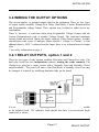
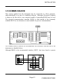
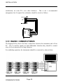
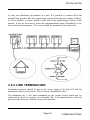
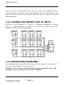
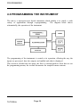
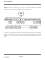
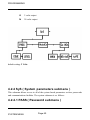
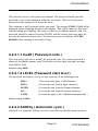
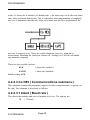
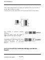
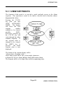
1
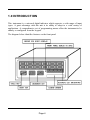
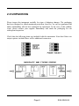
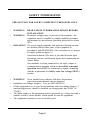
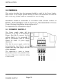
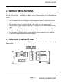
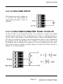
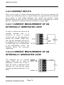
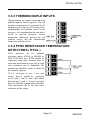
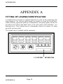
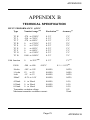
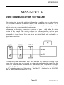
52-314-2063-03
DM4000U
SMART
INDICATOR
Whilst every effort has been taken to ensure the accuracy of this document, we accept
no responsibility for damage, injury, loss or expense resulting from errors or
omissions, and reserve the right of amendment without notice.
This document is issued by Status Instruments Ltd and may not be reproduced in any
way without the prior written permission of the company.
Page 1
August 2003
CONTENTS
GETTING STARTED
1.0
INTRODUCTION
3-5
2.0
UNPACKING
6
INSTALLATION
3.0
WIRING
7 - 24
USER GUIDE
4.0
PROGRAMMING
25 - 67
5.0
OPERATION
68 - 73
Appendix A
FITTING OF LEGEND ID
Appendix B
SPECIFICATION
75 - 79
Appendix C
TROUBLESHOOTING
80 - 81
Appendix D
MAINTENANCE
82
Appendix E
USER COMMUNICATION SOFTWARE
83 - 92
Index
74
93 - 94
Page 2
GETTING
STARTED
Page 3
1.0 INTRODUCTION
This instrument is a universal digital indicator which supports a wide range of input
types. A great advantage with this unit is its ability to adapt to a wide variety of
applications. A comprehensive set of programming menus allow the instrument to be
entirely re-configured from the keypad.
The diagram below identifies features on the front panel.
Page 4
The diagram of the rear panel below shows the slot positions for all electrical
connections.
There are two output slots into which the user may fit a range of options, including
relays, current re-transmission and voltage output boards. In addition there is also a
communications board slot allowing up to 30 units to be directly networked together
to a host computer.
A schematic of the unit showing internal power supplies and possible options is
shown below
Page 5
2.0 UNPACKING
Please inspect the instrument carefully for signs of shipping damage. The packaging
has been designed to afford maximum protection, however, we can not guarantee that
undue mishandling will not have damaged the instrument. In the case of this unlikely
event, please contact your supplier immediately and retain the packaging for our
subsequent inspection.
Check that the following items are included with the instrument. Note that if there are
output options included there will be additional connectors.
Page 6
SG4-2069-04
INSTALLATION
Page 7
SAFETY INFORMATION
THIS SECTION FOR USE BY COMPETENT PERSONNEL ONLY
•
•
•
WARNING
READ SAFETY INFORMATION BELOW BEFORE
INSTALLATION
WARNING Hazardous voltages may be present on the terminals - the
equipment must be installed by suitably qualified personnel
and mounted on an enclosure providing protection to atleast
IP20.
ISOLATION The power supply terminals and associated internal circuitry
are isolated from all other parts of the equipment in
accordance with BS EN61010-1 for connection to a Category
II supply (pollution degree 2)
Functional isolation (500v max) is provided between input
and output circuits, and between inputs and communications
(where fitted).
Any terminals or wiring connected to the input, output or
communications terminals which are accessible in normal
operation must ONLY be connected to signals complying
with the requirements for Safety extra low voltage (SELV)
circuits.
•
•
•
•
•
WARNING
If not installed in accordance with these instructions,
protection against hazards may be impaired
Installation overvoltage category - 2 (as per BS EN61010-1)
(If this equipment is to be used in environments with overvoltage category 3,
transient suppressors should be installed on wiring greater that 50VAC or
75VDC).
The Mains supply to the equipment must be protected by a 1Amp fuse and a
suitable switch or circuit breaker which should be near the equipment.
The equipment contains no user serviceable parts.
Page 8
MECHANICAL INSTALLATION
When installing the instrument into the panel, the following dimensions should be
taken into account.
The unit is held in the Panel by two metal clamp bars, on diagonally opposite corners,
fitted from the rear. A gasket is available, and should be fitted wherever sealing of the
instrument is required. See diagram below.
The maximum panel thickness is 3.5mm with a gasket and 4.5mm without. The gasket
has a self adhesive side which should be stuck to the panel around the cutout. The
instrument may then be inserted and tightened against the gasket to form a seal. The
panel should be clean and smooth for the seal to be effective.
Page 9
INSTALLATION
3.0 WIRING
This section describes how the instrument should be wired for the Power Supply,
Input Sensor or any Output options that may be fitted. All connections are made to
three or five way sockets which are removable for ease of wiring.
Installation should be undertaken in accordance with relevant sections of
BS6739 - British Standards code of practice for "Instrumentation in Process
Control Systems: Installation design and practice".
See important safety information on page 8
3.1 POWER SUPPLY
The Power supply rating will be
indicated on the top of the instrument.
Ensure that this is correct for the
voltage that is to be connected. If
there is a difference, refer to Service
Manual for details of power supply
adjustment.
Note that the power supply socket has
had polarisation keys fitted to prevent
insertion into any other plug at the rear
of the instrument.
The connection is made as shown.
Ensure that no bare wire protrudes from
the rear of the power connector risking
a short circuit.
POWER SUPPLY
Page 10
INSTALLATION
3.2 WIRING PRECAUTIONS
The unit can accept a variety of sensor inputs, some of which produce very small
voltages. Therefore it is advisable to adhere to the following rules of good installation
pratice.
•
•
•
•
•
•
Do not install close to switchgear, electromagnetic starters, contactors, power
units or motors.
Do not have power or control wiring in the same loom as sensor wires.
Check power supply voltage is the same as printed on the label attached to the
unit.
Check wires (especially the power supply voltage wires) are not loose before
switching on the unit.
Use screened cable for sensor wiring with the screen earthed at one end only.
Follow the wiring instructions in this manual
3.3 SENSOR CONNECTIONS
All sensor connections are made via the five way socket at the rear of the unit as
shown below.
Page 11
SENSOR CONNECTIONS
INSTALLATION
All sensor connections are summarised in the diagram below.
3.3.1 DC VOLTAGE INPUTS
The unit has two individual voltage inputs. One supports millivolt inputs ( up to
100mV ), and the other, voltage inputs up to 10 volts.
If the voltage input to be measured is to be no greater than 100mV it is connected to
the millivolts input. If the signal is less than 10 volts but greater than 100mV, it is
connected to the Voltage input. Any voltages greater then 10 volts may still be
measured, but must be divided down first. Each of these cases is discussed in more
detail below.
3.3.1.1 MILLIVOLTS INPUT
This input accepts signals up to
+/-100mV in normal operation. The
signal source must be connected to
pins 4 and 5 as shown opposite.
SENSOR CONNECTIONS
Page 12
INSTALLATION
3.2.1.2 VOLTAGE INPUT
This input pin can take voltages up
to 10 volts. The signal should be
connected between pins 3 and 5 as
indicated.
3.2.1.3 VOLTAGES GREATER THAN 10 VOLTS
In order for these to be measured correctly, it is necessary to connect some simple
external circuitry outside the unit to divide down the voltage to a nominal maximum of
10volts. This is done using a resistor divider chain as shown in the diagram below.
The choice of resistors are given as the nearest preferred values to those calculated in
the equations for R1 and R2 below. It is possible to correct for any errors in the
divide down chain by making R2 a trimmer, or correct by adjustment of scale range.
Care must be taken to insulate any high voltages to protect from electric shocks or
damage to any other equipment.
Page 13
SENSOR CONNECTIONS
INSTALLATION
3.2.2 CURRENT INPUTS
There are two types of current measurement possible, the first type measures the
current of an external loop, that is, a current that has been generated from an external
power supply, or from another instrument. The second type measures current
generated from the units own 20V excitation supply. Before connecting up a current
input it is important to establish which one of these two groups apply.
3.2.2.1 CURRENT MEASUREMENT OF AN
EXTERNALLY GENERATED LOOP
In order to measure the current in an
externally generated loop, it is
necessary to insert a resistor
in-circuit and use the instrument to
measure the resultant voltage drop.
Note that the instrument will need to
be configured as a 1-5V input and not
a 4-20mA input; this is described later
in the programming section. The
diagram shows the necessary
connections.
3.2.2.2 CURRENT MEASUREMENT OF AN
INTERNALLY GENERATED LOOP
The instrument has an excitation
supply which can be used for
generating a current loop. If this is
used, the circuit is connected in the
following way. Note that the current
input has an internal impedance of 50
ohms.
SENSOR CONNECTIONS
Page 14
INSTALLATION
3.3.3 THERMOCOUPLE INPUTS
Thermocouples are simply connected to the
millivolt input as shown opposite. The cold
junction compensation is performed by the
integral sensor at the rear of the unit or by a
programmable cold junction value. For best
accuracy, it is important that the rear plate is
fitted to prevent draughts causing
temperature differences between the cold
junction sensor and the thermocouple
connection with the device.
3.3.4 Pt100 RESISTANCE TEMPERATURE
DETECTORS ( RTDs )
These detectors are for platinum
resistance inputs (Pt100) to BS1904 or
DIN 43760 three wire. RTDs should be
connected using three identical wires in
order that measurement errors due to lead
wire resistances can be eliminated. The
connections should be made as shown in
the diagram opposite.
If it is necessary to use a two wire
sensor, then it should be connected
across pins 2 and 4, with a link added
between pins 4 and 5. It must be noted,
however, that this configuration will suffer
from inaccuracies due to the total series
resistance of the wiring.
Page 15
SENSOR
INSTALLATION
3.3.5 TRANSDUCER BRIDGE INPUT
A transducer bridge requires two sets of connections. A power supply and bridge
output. The bridge output is treated as a millivolts signal and connected between pins
4 and 5 as in the diagram below.
Note that the power supply could be from the units bridge excitation output option or
an external power supply.
SENSOR CONNECTIONS
Page 16
INSTALLATION
3.4 WIRING THE OUTPUT OPTIONS
This section applies to optional outputs fitted to the instrument. There are four types
of output option available; Change-Over Relay, Dual Relay, Current Retransmission
and Programmable voltage Output. These options may be fitted to either slot in any
combination.
There is, however, a restriction when using Programable Voltage Output with the
Current Retransmission card or another Voltage Output. The combined maximum
current should not exceed 50mA; the supply capacity of the Output options. Another
consideration with a pair of analogue output options ( Voltage or Current ) is that
although there is 500V * isolation from the Input, there is no isolation between output
slots.
* See safety information on page 8
3.4.1 RELAY OUTPUTS, option 1 and 2
There are two types of relay outputs available, Dual relay and Change-Over relay. The
dual relay board has two independent contacts sharing the same common. The
Change-over relay has a single contact with a Normally Open and Normally Closed
output available. The power-off state of the Dual Relay is normally closed, but may
be changed, if required, by modifying hardware links on the board.
It is recommended that a proprietary suppressor network is fitted as close as possible
to the inductive load. DC inductive loads should also have a reverse biased diode
connected as shown.
Page 17
RELAY OUTPUT
INSTALLATION
The contact states both these types of relays are summarised in the table below.
If the current to be switched is very low (<100mA) the varistors on the relay board
may need to be removed.
RELAY OUTPUT
Page 18
INSTALLATION
3.4.2 Current Output (Retransmission), option 03
The Current output board can support current loops generated from an external
power supply, or generate a loop source from the instrument itself. Both of these
cases are shown in the diagrams below.
Note that connecting directly across pins 1& 3 may cause damage to the
output card.
The instrument may be used as a voltage output by connecting a suitable resistor
between pins 1 and 2.
For example by placing a 250 ohm resistor across pins 1 and 2, and setting the output
board to 4-20mA the voltage output will produce a voltage between 1 and 5 volts.
Page 19
CURRENT OUTPUT
INSTALLATION
3.4.3 Voltage Output ( Bridge Excitation ),option
04
There are two options. Either a programmable 2 to 20 volt output or a fixed 24 volt
output. The connections for both cases are shown below.
VOLTAGE OUTPUT
Page 20
INSTALLATION
3.5 COMMS BOARD
This section explains how the instrument may be connected to a Host computer,
either individually or as part of a multidrop network. Although a Personal Computer
is shown as the host device, any computer capable of generating RS485 may be used.
The electrical communications standard, RS485 is used instead of the commonly
available RS232 as its robustness is more suitable for process instrumentation.
The Comms board is fitted in its own dedicated slot accessible from the rear of the
instrument as identified below.
Although RS485 is the recommended interface, RS232 has been found to operate
COMMS
PORT
1
2
3
4
5
9 WAY
RX
2
TX
3
SIG GND
5
DCD
DSR
RTS
CTS
1
6
7
8
Page 21
25 WAY
3
2
7
8
6
4
5
COMMUNICATIONS
INSTALLATION
satisfactorily on some PCs over short distances. This is not a recommended
arrangement, but if required for evaluation, should be wired as follows.
SMART INDICATOR
485
CARD
1
2
3
4
5
GND 1
Amplicon
Liveline
Model
485F25
EN 2
TX-B 3
LINK
TX-A 4
RX-A' 5
RX-B' 6
VDC 7
GND 8
+5 TO +13V DC
3.5.1 BASIC CONNECTIONS
The diagram below shows the basic connections between the instrument and a Host
PC. The Tx and Rx signals are both differential, therefore they should be twisted
wires for best operation over long distances.
For multidrop operation, the instruments should be connected as shown below.
COMMUNICATIONS
Page 22
INSTALLATION
As only one instrument can transmit at a time. It is possible to connect all of the
transmit lines together, this does depend upon each unit being given a unique 'address'
or device number, a subject which is dealt with in the programming section of this
manual. It may be necessary to screen the communications wiring if installed in a very
noisy electrical environment. The screen should be grounded at one point only.
3.4.2 LINE TERMINATION
Termination resistors should be put on the receive inputs of the Host PC and the
instrument furthest away from it. This is shown schematically above.
The instrument has a 100 ohm termination on the comms board which may be
connected in-circuit by moving a user selectable link. The normal position, when the
unit leaves the factory is with the resistor disconnected.
Page 23
COMMUNICATIONS
INSTALLATION
There is more to the termination at the Host PC receiver. The additional resistors
ensure that when all units are tri-state, the differential line rest in an 'idle' state and
therefore do not risk detection of spurious data due to noise or slight offsets in the
differential inputs.
3.5.3 CONNECTING MORE THAN 32 UNITS
RS485 has a drive limitation of 32 receivers. If additional instruments are required
(there is a logical maximum of 99 units ) it is necessary to buffer the Host PC
transmitter as shown in the diagram below.
3.5.4 GROUNDING PROBLEMS
Each instrument has an internal link which connects the comms 0v to unit ground. If
this causes any problems, it may be removed.
Warning Do not remove the Earth strap from the instrument as this could
potentially leave the instrument in an unsafe condition.
COMMUNICATIONS
Page 24
USER
GUIDE
Page 25
PROGRAMMING
4.0 PROGRAMMING THE INSTRUMENT
The unit is a microprocessor based instrument which enables it to satisfy a wide
variety of applications through re-programming.
The diagram below shows
schematically, the operation of the instrument.
The programming of the instrument is central to its operation, effecting the way the
inputs are processed, how the outputs are handled and what is displayed.
This section is divided into two parts, the first is a tutorial guide to show how to use
the programming menus, the second documents the complete menu contents.
TUTORIAL
Page 26
PROGRAMMING
4.1 PROGRAMMING TUTORIAL GUIDE
Before starting with the Tutorial, it is useful to understand that the unit has three
operating modes. These are :DISPLAY PROCESS VARIABLE MODE
MENU MODE
EDIT MODE
THE DISPLAY PROCESS VARIABLE MODE is the principal mode of
operation. From here, the Process Variable is displayed and all other modes are
accessed. The unit will always time-out back to this mode from any other mode of
operation.
THE MENU MODE gives the user access to the programmable parameters within
the unit. It is called a Menu Mode because the parameters are arranged in lists
according to their type.
THE EDIT MODE is entered into from the Menu Mode and allows the user to
inspect or modify a parameter value.
Page 27
TUTORIAL
PROGRAMMING
4.1.1 KEY DEFINITIONS
All programming is done using the
three front panel keys. How these
keys are used to program the
instrument is shown in this tutorial.
The functions of the keys are
summarised as follows. The black
symbols indicate the keys to press.
Shaded keys indicate that the keys
should pressed simultaneously.
4.1.2 GETTING INTO MENU MODE
The Menu mode is accessed from the Display PV mode by pressing the following
sequence of keys.
The display will now show SETPt. In order to understand what this means, the
following diagram shows where we are within the basic or Root menu structure.
TUTORIAL
Page 28
PROGRAMMING
4.1.2.1 MOVING AROUND THE MENU
We can browse through the other items in the Root menu by pressing
Subsequent presses of Cycle moves the menu position from right to left on the
previous diagram of the root menu. Notice that after reaching CALIB, the menu
position wraps around to the start. This principle of menu operation is applied
throughout the system.
4.1.2.2 GETTING INTO A SUBMENU
Up to now we have simply moved within the Root menu, in order to get into a
submenu, we must first cycle around the Root menu until the required submenu is
displayed.
For the purposes of this tutorial press the
CYCLE key until InPut is displayed.
In order to get into the INPUT menu
simply press the SHIFT key.
Page 29
TUTORIAL
PROGRAMMING
SENSor will now be displayed; we are now in the Input submenu. The diagram
below shows our position in relation to other items in the menu.
As before, pressing the CYCLE moves the menu position from left to right, wrapping
around at the end. Do not worry if the contents of the menu as shown above is not
exactly as you find; the unit alters items in the menu list depending upon settings
made.
TUTORIAL
Page 30
PROGRAMMING
4.1.3 EDITING A PARAMETER
Although the items displayed in the menu can either be submenus or parameters, most
of the items in the Inputs menu are parameters. This means that they can be edited.
Press the CYCLE key until SENSor is
displayed,
and then press SHIFT.
We are now in EDIT mode. This mode is
indicated by a flashing display. The display shows the contents of the parameter being
edited. The flashing entry is most likely to be currnt. This means that the Input
sensor type was previously set to monitor current inputs.
This item is changed by pressing the INC
key.
The choice of options available will be found to be as follows:INCrement the edit options around until Volts is displayed flashing.
Note that whilst the display is flashing, the option on the display has not been saved
to memory.
Page 31
TUTORIAL
PROGRAMMING
To select an option, the ENTER key sequence is used.
Now press ENTER.
The display will be seen to stop flashing
momentarily before returning to Menu
mode. Instead of returning back to the
SENSor entry, rANgE will now be displayed. The system has automatically stepped
on to the next entry to speed the process of programming.
This method of editing parameters is repeated broadly throughout the menu structure,
with the exception of programming number fields which will be dealt with next.
The method of editing a field is a bit different, though as easy as for any other entry.
As before, we will see it through an example.
Cycle around the Inputs menu until Hi is displayed.
This is the engineering high range value,
although its function is unimportant in the
tutorial, it simply provides a numeric field to
edit.
As before pressing SHIFT takes us into the edit mode.
The value on the display will have its most
significant digit flashing and represents the
value previously entered for the engineering units high range.
As before, the INC key modifies the editable value, but this time, this will only be the
digit flashing. This digit is said to be under
the edit cursor.
To move the edit cursor, press the SHIFT key.
TUTORIAL
Page 32
PROGRAMMING
The edit cursor moves one digit to the
right. If the SHIFT key is repeatedly
pressed, the edit cursor will be seen to
wrap around to the most significant digit once more.
Therefore it can be seen how a number may be programmed in this field by selective
use of the INC and SHIFT keys. We could enter the edited value as done in the
previous example, but for the purposes of this tutorial we shall abandon the edit.
This is done using the ESCAPE key
sequence.
Pressing this returns us to the MENU mode, showing FiltEr, the next item in the
Input menu.
We could go on and program other items within this or other menus using the same
principles as we have done in the previous examples. Instead, we shall return to the
Root menu, and then back to the DISPLAY PV mode.
4.1.4 RETURNING FROM SUBMENUS
It has been shown that the method of getting into a submenu is pressing the SHIFT
key on a submenu item. The reverse operation is to press the ESCAPE key.
This may be done anywhere in a
menu. Pressing the ESCAPE key from
our current position in the Inputs menu
takes us back to the Root menu.
OUtPUt will now be displayed, as the menu position has automatically stepped on to
the menu item.
The Root menu, as its name suggests is not a submenu. Pressing the ESCAPE key
sequence whilst in the Root menu will take the user out of MENU mode and into the
DISPLAY PV mode. Thus the monitored process variable will be shown on the
display.
Note that escaping to DISPLAY PV mode saves all programmed data to non-volatile
memory, retaining it during switch off.
Page 33
TUTORIAL
PROGRAMMING
4.2 THE MENUS
The previous section explained how to get into program mode, to move around the
menus and how to edit. This section details the contents of the menus and explains
how to program the unit for your own particular application.
As described before, Program mode is entered by pressing ENTER then CYCLE
from the process variable display. This takes the system into the Root menu. The
Root menu is divided into five submenus: SETPOINTS, INPUTS, OUTPUTS,
SYSTEM and CALIBRATION.
Note: If there are analog output options fitted ( Current output or Voltage output ) in
both output slot positions, there will not be any setpoints available and the
SETPOINT submenu will be removed from the Root menu.
ROOT MENU
Page 34
PROGRAMMING
4.2.1 The SEtP (SETPOINTS) submenu
This submenu is provided as a quick means of modifying setpoints. Only the setpoint
values are available to be changed. The availability of the setpoints depends upon the
output options fitted. The logic directing this is discussed in detail in section 4.2.3,
under the Output submenu section. With this in mind, it should be taken that any or all
of the setpoints ( 1 to 4) could be unavailable and therefore removed from the
submenu. If all setpoints are unavailable then the entire submenu is occulted. The
submenu is represented as follows:-
In each case, the editable value is the setpoint in engineering units. The number of
decimal places for this field is defined by rES in the Inputs menum see 4.2.2.5.
The default value for all setpoints is zero.
Page 35
SETPOINT MENU
PROGRAMMING
4.2.2 The INPUt submenu
This submenu is used to program all the characteristics of the input sensor and any
signal conditioning that may be required. The selection of an option in the list may
effect items further down. Therefore, during programming, the user should start at the
top of the menu and work down, to avoid setting an option which may later become
obsolete. For instance if a temperature sensor is selected, then there is no requirement
to select the engineering range.
The structure of the Input menu is represented in the following diagram.
INPUT MENU
Page 36
PROGRAMMING
4.2.2.1 SENSOr ( Type of sensor connected )
This parameter defines the type of electrical sensor connected.
There are four options.
currnt
( Current inputs, internally generated loop )
tc
( Thermocouple input )
VoltS
( Voltage input, including millivolts )
rtd
( Resistance thermometer )
default setting: currnt
4.2.2.2 rANgE ( electrical range for voltage or
current inputs)
This Range parameters will only be available if the sensor option has been set to either
current or voltage. The options available will vary between these two settings.
4.2.2.2.1 rANgE [ SENSOr=currnt ]
If the sensor type has been set to current, the following options are available.
4-20
( Internally generated 4-20mA )
0-20
( Internally generated 0-20mA )
0-10
( Internally generated 0-10mA )
default setting: 4-20.
4.2.2.2.2 rANgE [SENSOr=VOLtS]
If the sensor type has been set to voltage, the following options are available.
0.100
( 100mV on the millivolt input )
1
( 1 Volt on the voltage input )
1-5
( 1 to 5 volts on the voltage input )
10
( 10 volts on the voltage input )
default setting: 0.100
Page 37
INPUT MENU
PROGRAMMING
4.2.2.3 SENSOr ( Type of thermocouple )
This menu option is only available if a thermocouple has been selected as sensor type.
This option allows the user to set the thermocouple type. The options are:CA
( K type thermocouple )
J
( J type thermocouple )
t
( T type thermocouple )
r
( R type thermocouple )
S
( S type thermocouple )
E
( E type thermocouple )
F
( F type thermocouple )
n
( N type thermocouple )
b
( B type thermocouple )
Default setting: CA.
4.2.2.4 UnitS ( Temperature sensor units )
This item is only available if a temperature sensor has been selected, that is, either a
thermocouple or an RTD. The two options are:dEg C ( Degrees Centigrade )
dEg F ( Degrees Fahrenheit )
Switching between these two has the effect of changing the engineering range between
Degrees centegrade and Degrees Fahrenheit.
Default setting: dEg C.
INPUT MENU
Page 38
PROGRAMMING
4.2.2.5. rES ( Engineering units display resolution )
This option defines the number of decimal places displayed for the process variable.
There are four options:
8888
No places of decimal ( integer value )
888.8
One place of decimal
88.88
Two places of decimal
8.888
Three places of decimal
Note that the Low and High engineering range adopts this resolution, as do the Rate
setpoints, so consideration needs to be given to appropriate resolution for the
required application. It is advised that the number of decimal places is set before the
engineering range is programmed. There are five digits allocated for all engineering
values, so the number of significant figures must fit within this field.
If there are more significant digits than can be displayed, the number will be
right justified.
default setting: 888.8 (One place of decimal)
4.2.2.6 CJ (Cold Junction Select )
This is only shown if thermocouple has been selected as input type. This entry
provides choice of cold juction compensation between a internal thermistor measuring
the actual input terminal temperature or a set programmable temperature.
iNtErN
( Internally measured input terminal temperature )
PrOG
( Programmable Cold junction )
default setting: iNtErN
4.2.2.7 PrOGCJ ( Programmable Cold Junction )
This is shown if CJ has been set to PrOG and contains the value with which the
thermocouple calculation will use as cold junction. The value is in engineering units;
Degrees C or Degrees F.
Page 39
INPUT MENU
PROGRAMMING
Default setting: 0.0
4.2.2.8 LO and HI ( Rate Engineering range )
LO and HI are used to define the engineering range for Rate.
This range applies to low and high electrical inputs being monitored by the unit. For
example, if the electrical input has been set to Volts, on the 100mV range, and it is
required that the Rate value be 0.0 at 0mV input and read 50.0 at 100mV, LO and HI
are set to the following values:
LO = 0.0 HI = 50.0
The display value will increase linearly from 0.0 to 50.0 as the millivolts increase from
0 to 100. Similarly as the millivolts reduce from 0 to -100 the Rate falls from 0.0 to
-50.0. This relationship is shown on the following diagram.
On all ranges, a 7% overhead is allowed on the scale before the unit detects an
out-of-range signal. If the input signal is out of range at the positive end of the scale,
OVEr is displayed instead of the Process Variable. If out-of-range at the negative
end, Under is displayed.
Note that it is quite acceptable to have a reverse acting engineering range, where LO
will be greater than HI.This method of setting the engineering range may also be used
for removing gain or offset errors from the system being measured.
INPUT MENU
Page 40
PROGRAMMING
Note that the maximum value that may be entered is 64000.
default setting: LO: 0.0; HI: 100.0
4.2.2.9 brnout ( Temperature Sensor burnout )
Burnout enables the user to select up-scale (Hi) or down-scale (Lo) burnout
condition. This is available for thermocouple or RTD sensors only, and effects the
operation of all alarms and output options. When a temperature sensor is detected to
be open circuit, the burnout comes into operation, forcing the Process Variable
up-scale or down-scale. burn is shown on the display in place of the Process
Variable display.
The options are:
Hi ( High scale burnout )
Lo ( Low scale burnout )
default setting: Hi
The factors which can cause a burnout error are any of the following :Thermocouple open circuit
Cold junction thermistor temperature out of bounds
Cold junction thermistor electrical fault
Any RTD wire becoming open circuit
Page 41
INPUT MENU
PROGRAMMING
4.2.2.10 FiltEr ( Input filtering or smoothing )
If an input is particularly noisy, it is possible to filter out noise using this
programmable feature. There are eight filter values which may be selected. These filter
factors represent the time it would take a step change in an input value to reach
approximately 63% of its final value.
The following filter factors are available:
nonE
( Filtering switched off )
0.5 SEC
( Filter Factor 0.5 seconds )
1 SEC
( Filter Factor 1 second )
2 SEC
( Filter Factor 2 seconds )
4 SEC
( Filter Factor 4 seconds )
8 SEC
( Filter Factor 8 seconds )
16 SEC
( Filter Factor 16 seconds )
INPUT MENU
Page 42
PROGRAMMING
32 SEC
( Filter Factor 32 seconds )
default setting: 2 SEC Also see jump out in section 4.2.2.11
4.2.2.11 JP out ( Filter jump out )
This sets the change in input value, expressed as a percentage of full scale, below
which the filter operates and above which the filter is inoperable. This enables the
indicator to respond quickly to large changes, whilst filtering smaller noisy signals.
The diagram below shows the operation of the Jumpout on a filtered input. Each of
the waveforms is based upon the same raw input 'A'. By setting the Jumpout band
just greater than the noise level; the filtering is switched off for any change in actual
signal. In this way, a compromise between heavy filtering and signal response can be
reached.
The following options are available:
nonE
( No jump out, filter in operation all of the time)
1 PEr
( Jump out band, 1% of engineering range )
5 PEr
( Jump out band, 5% of engineering range )
Page 43
INPUT MENU
PROGRAMMING
10 PEr
( Jump out band, 10% of engineering range )
Note that 1% of engineering range for thermocouples is 20 degrees and for RTDs is
10 degrees.
default setting: 1 PEr
4.2.2.12 Cond ( Input conditioning for Current
and Voltage ranges)
This feature is available for Voltage and Current inputs only, and enables the user to
specify one of the following input characteristics. This characteristic is then applied to
the Raw input.
The five options are:
LinEAr
( Linear relationship, no conditioning )
USEr
( User defined characteristic. See 4.2.2.13 )
S root
( Square root Law. See 4.2.2.14 )
root 32
( Power 3/2. See 4.2.2.15 )
INPUT MENU
Page 44
PROGRAMMING
root 52
( Power 5/2. See 4.2.2.15 )
default setting: LinEAr
4.2.2.13 User linearisation
Selection of this option for Cond allows access to the User submenu. Within this
menu, thirteen points may be programmed to relate electrical input to engineering
value. These points are represented by IN and OUT entries within the menu, where IN
are the electrical inputs and OUT the resultant engineering value. An example of a user
linearisation utilising all thirteen points is shown below.
There are a few rules which should be followed when using this facility.
a)
The HI and LO values for engineering range should have been set before any
entry of data. Any engineering values entered should lie between HI and LO.
b)
The entries for the electrical inputs should progressively increase. There is no
such restriction on the engineering units.
c)
If not all thirteen points are used, it is necessary to reproduce the values in the
last entry in entry 13.
Page 45
INPUT MENU
PROGRAMMING
d)
Any electrical input falling outside the bounds specified by the table will be
regarded as out of bounds and under-range or over-range will be indicated
instead of the Process Variable. If a small amount of valid signal over/under
range is required, this must be built into the linearisation table.
4.2.2.14 Square Root.
When the Square root characteristic has been selected, the engineering range will still
increase from LO to HI as the electrical input is increased, but the response will be a
square root rather than Linear, see the diagram below.
The bottom 1% of the range is made to reflect equivalent linear value (times 10) to
avoid the near infinite gradient at zero. The Process Variable is set to Low engineering
range for all negative electrical inputs.
INPUT MENU
Page 46
PROGRAMMING
4.2.2.15 Power 3/2, 5/2 law
The root 3/2 and root 5/2 characteristics are for specific applications. For example,
calculation of Flow Rate from rectangular and ‘V’ notch weirs require these non-linear
corrections. The operation of the characteristic is the same as for square root except
that the bottom 1% is not made linear, the response is as follows.
Page 47
INPUT MENU
PROGRAMMING
4.2.3 OUTPUT SUBMENU
There are two types of outputs, namely digital (relays) or analogue, which are available
as options. Each of the two output slots can contain either of these options. The
processor identifies which options are present on power-up and invokes the
appropriate programming menus accordingly.
Entry into the outputs menu presents a list of submenus relating to the output cards
fitted. The conditions determining the availability of submenus is summarised below.
OUTPUT MENU
Page 48
PROGRAMMING
4.2.3.1 Relay alarms and LED alarms submenus
The submenus for the Relay and LED alarms are shown below.
Note that the only difference in content between them, is there is no SENSE option in
the LED submenu. This is because the SENSE option relates to the activation of a
Page 49
OUTPUT MENU
PROGRAMMING
relay and is therefore irrelevant if no relay is fitted. Both types of alarms activate a
discrete LED on the front panel of the instrument if triggered, although this is all a
LED alarm does, hence its name.
4.2.3.1.1 ActIOn ( Alarm action )
This programs how the alarm is to operate. The options are:
oFF ( Alarm inactive )
Lo ( Low alarm. Triggers when PV goes below setpoint )
Hi ( High alarm. Triggers when PV goes above setpoint )
dEv ( Deviation alarm. See Deviation band 4.2.3.1.5 )
Default setting: oFF
4.2.3.1.2 LAtch ( Latch enable for an alarm )
The options for this are:
FALSE ( Latch disabled )
trUE ( Latch enabled )
When Latch is enabled, the alarm remains set once triggered, even when the Process
Variable has returned to a non alarm condition. A non-latching alarm is self-resetting
when the alarm condition is removed.
Pressing CLEAR, from the Display Process Variable mode, clears a latched alarm if
not in an alarm state.
Default setting:FALSE
4.2.3.1.3 SEtP ( Alarm Setpoint )
This entry allows the user to program the setpoint value. This is entered in engineering
units. This can also be set from the SEtP menu ( see 4.2.1 ) which provides a quick
OUTPUT MENU
Page 50
PROGRAMMING
means of adjusting setpoints whilst running.
Default setting: 0.0
4.2.3.1.4 HySt ( Alarm hysteresis or dead band )
This enables the hysteresis or dead-band to be programmed. This is the difference
between the points at which the alarm triggers and releases and is expressed as a
percentage of engineering range. For high and low alarms, the alarm triggers exactly at
setpoint and is removed at the hysteresis level away from the setpoint. See example
based upon a high alarm below.
In the case of deviation alarms, the hysteresis is applied to each trigger point either
side of the setpoint.
Note that for thermocouples, a 1% hysteresis band would be equal to 20 degrees
Centigrade and 10 degrees Centigrade for an RTD.
Page 51
OUTPUT MENU
PROGRAMMING
default setting: 0.00
4.2.3.1.5 DEv ( Deviation band )
This option will only appear if the alarm action is set for deviation, and it signifies the
amount, as a percentage of the engineering range that the input variable may vary
before the alarm condition is activated. This is illustrated in the example below.
The deviation alarm creates two alarm trigger points; one above and one below the
setpoint. The trigger points are equally distant from the setpoint. This is known as the
deviation band and is a percentage engineering range.
OUTPUT MENU
Page 52
PROGRAMMING
Each of these trigger points may be regarded as an upper and lower setpoint, and as
such the operation of the hysteresis is as on individual upper and lower setpoints.
Note that 1% deviation represents 20 degrees Centegrade for a thermocouple and 10
degrees Centegrade for an RTD.
default setting: 0.00
4.2.3.1.6 SENSE ( Invert activation of relay )
This option sets the sense of the relay, ie in the event of an alarm, is the relay to be
energised or de-energised?
Page 53
OUTPUT MENU
PROGRAMMING
The options are:
noninv ( energise relay on alarm, de-energise normally )
iNv ( energise normally, de-energise relay on alarm )
This function is tied in with the fail safe requirements of the relay and its electrical
configuration. The following summarises all options.
Default setting: noninv
4.2.3.1.7 dElAy ( Delay before activation of alarm)
This option allows a delay time to be programmed ( in seconds ) which must elapse
between an alarm being detected and then indicated ( and relay state changed ).
The options are:
oFF
( No delay time )
1 SEC
( 1 second delay )
2 SEC
( 2 second delay )
5 SEC
( 5 second delay )
10 SEC
( 10 second delay )
15 SEC
( 15 second delay )
20 SEC
( 20 second delay )
If the alarm condition is removed during the delay period and then re-applied, the
delay time starts again from the time the alarm condition re-occurs.
Default setting: OFF
OUTPUT MENU
Page 54
PROGRAMMING
4.2.3.2 curnt1(3) CURRENT OUTPUT
(RETRANSMISSION ) BOARD
The current retransmission board provides a range of current output options. If fitted,
the following menu will be available from the Output menu.
4.2.3.2.1 SPAN ( Output current span )
Span is the current range at which the output board is to operate.
The options are:
4-20mA ( Output current will vary from 4 - 20mA )
0-20mA ( Output current will vary from 0 - 20mA )
0-10mA ( Output current will vary from 0 - 10mA )
Page 55
OUTPUT MENU
PROGRAMMING
Default setting: 4-20
4.2.3.2.2 tyPE ( Type of output operation )
This determines the type of operation. The choices are either fixed programmable
output or current retransmission based upon the process variable.
The options are:
rEtrAN ( Retransmission of the input )
PrESEt ( Constant preset output )
Default setting: rEtrAN
4.2.3.2.3 lo ( low retransmission range )
This is the engineering value at which the current output will be at its minimum value
(either 0 or 4mA), depending upon the span setting.
The value is entered as an engineering value.
Default setting: 0.0
4.2.3.2.4 hi ( high retransmission range )
This is the engineering value at which the current output will be at its maximum value
(20mA or 10mA). See the diagram below for an example of the operation of this
feature.
Note that it is acceptable for the hi range to be less than the lo; although both must be
within the span of the input engineering range. Note that the current output is limited
to the extremes of the current range selected.
Default setting: 100.0
The following diagrams on the next page show the different output responses for a
variety of configurations.
OUTPUT MENU
Page 56
PROGRAMMING
Page 57
OUTPUT MENU
PROGRAMMING
4-20mA
0-20mA
0-10mA
4.2.3.2.5 PrESEt ( Preset output value )
This line is only available if PrESEt has been selected as the tyPE of operation. In
this mode the current output will directly relate to the value set within this
programmable option. The value entered must fall within the hi and lo range and will
cause the maximum current to be output when set to the hi value and the minimum
output current when set to the lo value.
OUTPUT MENU
Page 58
PROGRAMMING
4.2.3.3 Vprog1 (3) Bridge Excitation board
This menu entry is available when a bridge excitation board is fitted in either slot 1 or
2. This is used to program a fixed voltage output from the following range of options.
2
2 volts output
2.5
2 volts output
3
2 volts output
3.5
2 volts output
4
2 volts output
4.5
2 volts output
5
2 volts output
6
2 volts output
7
2 volts output
8
2 volts output
9
2 volts output
10
2 volts output
12
2 volts output
Page 59
OUTPUT MENU
PROGRAMMING
15
2 volts output
20
20 volts output
default setting: 2 Volts
4.2.4 SyS ( System parameters submenu )
This submenu allows access to all of the system based parameters such as passwords
and communications facilities. The system submenu is as follows:
4.2.4.1 PASS ( Password submenu )
SYSTEM MENU
Page 60
PROGRAMMING
This provides access to the password submenu. The password facility provides
protected access to the submenus within the root menu. The level of password
protection works progressively down the menu.
This submenu is itself protected with a password. The message ENtEr, PASS will be
displayed before displaying the password template. This will be shown as four zeros
with the leading zero flashing. This may be edited as an ordinary numeric field. The
password should be entered. Pressing ENTER with the correct password takes the
user into the submenu shown above. An incorrect password displays ACCESS,
dEniEd before returning to the point of entry.
4.2.4.1.1 CodE ( Password code )
This entry allows the user to modify the password code. The current password is
shown as an editable numeric entry. Passwords are four digits long and can range
from 0000 to 9999.
default setting: 4000
4.2.4.1.2 LEvEL (Password start level )
The password level may be set up to start from any of the following levels.
SEtPt
( The passwords apply to all submenus )
INPUt
( Passwords start from in Input submenu )
OUtPUt
( Passwords start from the Output submenu )
SyS
( Passwords start from the System submenu )
CALIb
( Passwords apply to the Calibration submenu only )
default setting: CALIb
4.2.4.2 AUtOCy ( Automatic cycle )
Autocycle is a parameter which is used to control the way that the menu operation
Page 61
SYSTEM MENU
PROGRAMMING
works. If Autocycle is enabled ( its default state ), the menu steps on to the next menu
entry after each menu item action. This is convenient when programming a completely
new set of parameters into the unit. After each menu item has been programmed, the
next one is stepped on to. There are certain situations, however, when this is
inconvenient. Switching the Autocycle feature off ( Setting it to FALSE) will inhibit
any automatic stepping.
There are two possible options:
trUE
( Autocycle enabled )
FALSE
( Autocycle disabled )
default setting: trUE
4.2.4.3 Co NEt ( Communications submenu )
This submenu contains the parameters required for the communications to operate on
the unit. The submenu is described as follows:
4.2.4.3.1 bAud ( Baud rate )
This allows the transmit and receive baudrate to be set. The options are:
75
SYSTEM MENU
( 75 baud )
Page 62
PROGRAMMING
150 ( 150 baud )
300 ( 300 baud )
600 ( 600 baud )
1200 ( 1200 baud )
2400 ( 2400 baud )
4800 ( 4800 baud )
9600 ( 9600 baud )
Default setting: 9600
4.2.4.3.2 dEviCE ( Network device number )
It is possible to multidrop up to 99 instruments on one network. The device number
allocates a unique device reference for each individual unit. Note that without suitable
buffering, there is is a hardware limit of 30 instruments.
Default setting: 1
4.2.4.3.3 tyPE ( mode of Comms operation )
There are two modes of Comms operation possible. If the unit is to be operated
within a network, or a host computer accesses selective data then Slave mode is used.
The other mode, simply outputs a complete ASCII status report, consisting of the
process variable and the state of any alarms or output options. It is possible to dump
this data to a dumb terminal or to a printer.
The options are:
SLAVE
( Slave mode )
ASC OP
( Ascii output report mode )
Page 63
SYSTEM MENU
PROGRAMMING
Default setting:SLAVE
4.2.5 CALIb ( Calibration submenu )
This submenu, which will always have password protection, provides access to
enable the total (or partial) recalibration of the System. Casual access into this
submenu is therefore discouraged.
CALIBRATION MENU
Page 64
PROGRAMMING
Do not enter the CALIB submenu unless you know exactly what you are doing.
If the calibration settings are disturbed, it may be necessary to return the unit
to the factory.
The submenu may alter with the fitting of various output options, but is represented as
follows:
4.2.5.1 OFFSET ( Input offset adjustment )
This is a numeric value in engineering units which is added to the Process Variable
value in order to take out any system offset errors. This should be used with care as
there is no indication in the Process Variable display mode that this offset is being
applied and is thus capable of introducing an inadvertent error.
Default setting: 0.0
4.2.5.2 CAL 1 to CAL 10
(Input calibration)
These are used to calibrate the input system. Not recommended for users.
4.2.5.3 CLcUr1(3) Calibrate Current o/p board
Page 65
CALIBRATION MENU
PROGRAMMING
If the Current Output Board is to be fitted in the unit by the user, it is necessary to
use this entry to calibrate the option.
Connect up the Current output board to the Sensor input board as shown below.
Press ENTER, to commence automatic
calibration.
Note if the display reads either 'siglo' or
'sighi' recalibrate the output card again.
On completion ESCAPE back to the Process
Variable display mode.
This stores the
calibration information in non-volatile
memory.
4.2.5.4 CLvoP1(3) Calibrate Bridge excitation
board
CALIBRATION MENU
Page 66
PROGRAMMING
If the Voltage Output Board ( Bridge Excitation ) is to be fitted in the unit by the user,
it is necessary to use this entry to calibrate the option.
Connect up the Voltage output board to the
Sensor input board as shown below.
Press ENTER, to commence automatic
calibration.
Note if the display reads either 'siglo' or 'sighi' recalibrate the output card again.
On completion, ESCAPE back to the Process Variable display mode. This stores the
calibration information into non-volatile memory.
4.2.5.5 rESEt ( Reset all parameters to default )
Pressing ENTER on this option resets all programmable parameters to their default
values.
Page 67
CALIBRATION MENU
OPERATION
5.0 OPERATION
Previous sections have shown how the unit may be configured for user applications.
This section shows how the user may access additional information from the Display
PV mode and an explanation of how the instrument processes input data and activates
outputs.
5.1 USER OPERATION
There are a number of facilities available from the Display PV mode using the front
panel keys. These are summarised in the table below.
In addition, it is possible to get into Menu Mode by pressing
followed by
USER OPERATION
Page 68
OPERATION
5.1.1 VIEW SETPOINTS
The function of this mode is to provide a quick read-only access to the Alarm
setpoints. This operation is easier to do than to describe and is therefore shown
diagramatically below.
Pressing the CYCLE
key puts you into
VIEW
SETPOINTS
MODE. The display
will show the first
setpoint
number
available to be viewed,
possibly
SEtP1.
Successive pressing of
the CYCLE key will
cycle through the other
available setpoints. If
any setpoint value is
required to be viewed,
the SHIFT key is
pressed.
The actual
setpoint value is now
displayed.
The format of the setpoint display will be
<alarm action><Setpoint value>
where alarm action will be one of four single characters:o-Alarm Off; L-Low Alarm; h-High Alarm; d-Deviation Alarm
The Setpoint will be a five digit value scaled in engineering units.
Page 69
USER OPERATION
OPERATION
5.1.2 VIEW PEAK VALUE
The maximum Process Variable value measured since switch-on or last reset of
Peak/Valley (See 5.1.4), is continuously calculated within the instrument. The current
value may be inspected by pressing the SHIFT key whilst in Display PV mode. The
display will briefly show PEAc before revealing the actual peak value. This value will
remain displayed until 1s after the key is released. It will then return to the Process
variable display.
5.1.3 VIEW VALLEY DISPLAY
This operates in exactly the same way as the View Peak display except that the INC
key is used and the minimum Process Variable value displayed.
5.1.4 RESET PEAK/VALLEY & CLEAR LATCHED
ALARMS
Pressing the CYCLE and INC keys simultaneously performs two independent
functions. It sets the Peak and Valley values to the current Process Variable value
and it also clears any latched alarms.
USER OPERATION
Page 70
OPERATION
5.2 INSTRUMENT OPERATION
This section describes how the instrument processes input data and activates outputs.
The diagram below shows the sequence of processing.
5.2.1 INPUT PROCESSING
The electrical input is read in and converted to a digital value, corrections are made
for offset and drift. Readings are made ten times a second.
5.2.2 SIGNAL CONDITIONING
This process depends largely upon the menu programming. If the input is a
temperature sensor, the temperature characteristic is linearised here. If the input is a
voltage or current, the conditioning will be Linear, Square root, Power Law or User
defined, as programmed in the Inputs menu.
5.2.3 FILTERING
The programmable filter reduces noise from the conditioned input.
Page 71
INSTRUMENT
OPERATION
5.2.4 ERROR DETECTION
The instrument and the input is checked for a range of faults.
5.2.4.1 OPEN CIRCUIT
This is only checked for temperature sensors. If an open circuit is detected, the
process variable is forced full positive range or full negative range depending upon the
brnout setting in the Inputs menu. burn will be shown on the display in place of the
Process Variable display.
5.2.4.2 UNDER RANGE/ OVER RANGE
This is only checked for voltage or current inputs. If the input value is found to be
greater that 107% of full range, or less than -107% of full range, it is limited to 107%
or -107% of full range respectively. In this case, either OVEr or UNdEr is shown on
the display instead of the process variable value. This condition will also occur if the
user nonlin conditioning is used and the input falls below the minimum entry or
exceeds the maximum.
5.2.5 OUTPUT CONTROL
The alarm Relays, LED alarms and current retransmission options may all use the
filtered, conditioned Process Variable Value. This is the same value which is
displayed.
This process responds to any errors detected. If the input is a temperature sensor, an
open circuit will invoke the burnout condition, going to hi scale or low scale
depending upon the burnout programming.
5.6 DISPLAY
This will show the Process Variable in engineering units, filtered and conditioned. If
any errors have been detected, they will be indicated on the display. The number of
places of decimal will be as defined in the rES entry of the inputs menu, but if there
are more significant digits than can be displayed within the five digit field
available, the number will be right justified. For example 1234.567 will be
displayed as 1234.57. Although the electrical input is updated ten times a second, the
display is updated at the more visually practical rate of three times a second.
INSTRUMENT OPERATION
Page 72
OPERATION
5.7 INSTRUMENT FAULTS
The instrument continuously checks itself for correct operation. Detection of a fault
causes an error message to be displayed. The error messages are as follows :
Err
Err
Err
Err
Err
Err
Err
01
02
03
04
05
06
07
Non Volotile memory failure
RAM decode error
RAM size unrecognised
Input card error
EPROM checksum error
Ram Fault
Calibration data corruption fault
burn - SENSOR BURNOUT ERROR
Open circuit RTD (Any one of the three wires)
Open circuit Thermocouple
Cold junction thermistor temperature out of bounds
Cold junction thermistor electrical fault
OvEr / UndEr - INPUT SENSOR FAULT
Sensor over-range
Sensor under-range
Open loop current circuit
RTD short circuit
Open circuit mV
User non-lin function out of bounds
If an error message is displayed first remove power and re-apply. If the error
condition remains the instrument should be returned to the supplier.
Page 73
INSTRUMENT
APPENDICES
APPENDIX A
FITTING OF LEGEND/IDENTIFICATION
A standard sheet of legends is supplied which may be used for the engineering units
being displayed. The selected legend should be carefully cut from the overall sheet,
marked with any appropriate plant tag or identification, and pushed gently into the slot
provided in the bottom right hand corner of the front panel of the instrument (see
drawing below). These legends may be subsequently removed by means of a sharp
pin in the notch provided.
The Legend sheet is included with the instrument.
APPENDIX A
Page 74
APPENDICES
APPENDIX B
TECHNICAL SPECIFICATION
INPUT PERFORMANCE @20°C
Type
Nominal range(vii)
Resolution(vi)
TC
TC
TC
TC
TC
TC
TC
TC
TC
-270
-210
-270
0
0
0
0
0
1000
to
to
to
to
to
to
to
to
to
0.1°C
0.1°C
0.1°C
0.5°C
0.5°C
0.5°C
0.5°C
0.5°C
0.5°C
1°C
1°C
1°C
2°C
2°C
1°C
1°C
1°C
3°C
0
to 50°C(iii)
0.1°C
1°C(v)
K
J
T
R
S
E
F
N
B
Cold Junction
1200°C
760°C
400°C
1750°C
1750°C
650°C
600°C
1300°C
1800°C
Pt100
-200 to 800
10volts
1-5volts
1volt
100mV
-10V to
1V to
-1V to
-0.1V to
10V
5V
1V
0.1V
0.05°C
Accuracy(i)
0.1 +/- 0.1% (ii)
0.004%
0.008%
0.004%
0.004%
0.02%
0.04%
0.02%
0.02%
4-20mA
4 to 20mA
0.004%
0-20mA
0 to 20mA
0.004%
0-10mA
0 to 10mA
0.004%
Transmitter excitation voltage:
Maximum transmitter excitation current:
0.1%
0.1%
0.1%
19V
25mA
Page 75
APPENDIX B
APPENDICES
ADDITIONAL INPUT SPECIFICATION
Input
Average(iv)
Type
Acquisition Rate
T/C
6.8Hz
mV
8.9Hz
Volts
8.9Hz
Current
8.9Hz
Pt 100
1.7Hz
Cold junction(see T/C)
Isolation
Input impedance
(RTD current)
1M ohm(ix)
1M ohm(ix)
2M ohm
51 ohm
(less than 1.1mA)
NA
Power Supply:
2500VAC
Output Options: 500VAC
Comms Interface: 500VAC
Thermal drift
per ºC
0.001%
0.001%, 0.004% (x)
0.002%, 0.011% (xi)
0.001%
0.013°C
0.06°C
)
) see safety information
) on page 8
INPUT OVER-RANGE PROTECTION
Input Pin Usual Function Absolute Maximum Rating
1
0V
NA
2
RTD
30VAC(xii)
3
Volts
200VAC(xii)
4
Millivolts
200VAC(xii)
5
Curret
100mA
RELAY OUTPUT BOARD (OPTION 01 AND 02)
Maximum Rated Load
Maximum Power
Maximum Switching Voltage
7A@250V 7A@30V
1750VA
210W
380V
125V
Electrical Life
Mechanical Life
105 operations at rated load
50 million operations
Contact shunt capacitance
200pF
This is due to the Varistor and causes a reactance of 15Mohms at 50Hz.
Alarm detection delay
200mS
APPENDIX B
Page 76
APPENDICES
CURRENT RETRANSMISSION BOARD (SOURCE AND SINK) OPTION
03
PERFORMANCE @20°C
Accuracy:
Resolution:
Response:
Minimum Current O/P:
Maximum Current O/P:
Thermal Drift:
20uA
(0.1% of Max current)
2uA
(0.01% of the input range )
100ms for approx 63% of step change
0mA
21mA (approx)
900nA/ºC (0.0045% of Max current /ºC
)
Maximum loop impedance:
Output voltage drop @20mA:
Maximum external loop power supply voltage:
Minimum practical loop power supply voltage:
1000 ohms
(Source)
3 Volts
(Source & Sink)
30VDC
(Sink)
(RL* 21mA)+3 (Sink)
Where RL is the Loop impedance
Ripple Current:
Approx 5uA
Isolation:
Input
Power Supply
Comms I/F
500VAC
2500VAC
500VAC
)
) See safety information
) on page 8
VOLTAGE OUTPUT BOARD (OPTION 04) PERFORMANCE @20°C
Range:
Accuracy:
Maximum Current O/P:
Thermal Drift:
Ripple:
Fixed Voltage:
Programmable Voltages:
2-24 volts DC
24mV
(0.1% of Max voltage)
(xi)
50mA
1080uV/ °C (0.0045% of Max voltage /°C)
Approx 6mV
24V
2,2.5,3,3.5,4,4.5,5,6,7,8,9,10,12,15,20
Isolation:
Input
Power Supply
Comms I/F
Page 77
500VAC (see safety
2500VAC (information
500VAC (on page 8
APPENDIX B
APPENDICES
RS485 COMMUNICATION OPTION
GENERAL
Configuration
Maximum fan-out
Baud Rate
Data bits
Start bits
Stop bits
Parity
Maximum line length
Protocol
Four wire, Half Duplex
32 units(viii)
9600
8
1
1
none
4km
based on ANSI X3.28
TRANSMITTER
Maximum differential output voltage
Output voltage with 50ohm load
5v
>1.5v
RECEIVER
Differential input threshold voltage
Input receiver impedance
Common mode range
+/-200mV
12kohms
-7v to +12v
ENVIRONMENTAL
Ambient operating temperature range
Ambient storage temperature range
Relative Humidity
EMI Emissions
EMI Susceptibility
Safety
Power Supply
Power consumption
Max in-rush current
Front panel sealing(with gasket)
IP65
APPENDIX B
0 to 50°C
-20 to 80°C
20% to 95% non condensing
BS EN61326
BS EN61326
BS EN61010-1
240VAC,110VAC,24VAC 50/60Hz
6.5Watts max
100mA @240VAC
Page 78
APPENDICES
PHYSICAL
Dimensions
Mounting
Terminals
Weight
48 x 96 x 140mm
Panel cutout(91 to 92)mm x (43 to 44)mm
All two part captive screw terminals
850g
(i)
The accuracy values represent +/- spread from nominal. Unless otherwise
stated '%' represents the percentage of full scale value.
(ii) '%' represents percentage of reading in stated units
(iii) Represents the valid thermistor temperature range used for measuring Cold
junction temperature.
Slight internal warming from the unit means that temperature is 3 or 4°C
above ambient.
(iv) Average taken over a 1 second time frame. Acquisition defined as complete
refresh of electrical sensor value including readings to compensate for gain
and offset errors.
(v) Cold junction accuracy includes thermal tracking error, temperature
measurement error and linearisation error. This should be added to the
individual thermocouple accuracy to get an overall accuracy value.
(vi) '%' represents percentage of full scale value.
(vii) Input is measured correctly within a small margin outside the normal range.
This is 7% for bipolar (+/-) electrical inputs. Current inputs that go down to
zero do not under-range otherwise all other sensor inputs have a 7%
over/under-range margin.
(viii) This may be extended with suitable buffering
(ix) There is an internal 10M ohm pull down resistor to -2.5V. This is only
significant for high source impedance mV inputs.
(x) 50mV and 100mV respectively.
(xi) 1V and 10V respectively.
(xii) With respect to Pin 1 or Pin 5.
Page 79
APPENDIX B
APPENDICES
APPENDIX C
TROUBLESHOOTING
1) UNIT IS COMPLETELY DEAD
1.1) Check supply voltage is present on the rear connector
1.2) Check that supply voltage corresponds with voltage stated on the top
of the instrument
1.3) Consult service manual for instructions on replacing internal fuse
2) INCORRECT READING
2.1) Check that the unit is set up for the correct sensor type
2.2) Check that the Engineering range has been set correct for voltage
and current and correct units for temperature sensors.
2.3) Check that thermocouples have correct compensation cable and the
polarity is correct.
2.4) Check that all three wires are connected properly for an RTD.
3) UNDER/OVER RANGE
3.1) Check that the sensor wiring is correct.
3.2) Check that voltage/current sensor is not open circuit
3.3) Check that the unit is set up for correct sensor
APPENDIX C
Page 80
APPENDICES
4) ERROR CODES
Several error codes may appear due to the internal self checking of the instrument.
These indicate serious faults which cannot be rectified by the user. In the event of
these codes being displayed, the unit should be returned to the supplier.
The Error Codes are as follows:
Err 01
Non Volatile memory failure
Err 02
Ram decode error
Err 03
Ram size unrecognised
Err 04
Input card Error
Err 05
EPROM Checksum error
Err 06
RAM fault
Err 07
Calibration data corruption fault
Page 81
APPENDIX C
APPENDICES
APPENDIX D
MAINTENANCE
The instrument is a precision piece of electronic measuring equipment, and yet, due to
the nature of its design, requires very little maintenance.
1) CLEANING
The only cleaning required is to wipe the front panel with a damp cloth containing a
small quantity of detergent.
DO NOT use an abrasive cleaner
DO NOT use any industrial solvents as they might affect the polyester membrane.
DO NOT apply water to any other part of the instrument other than the front panel.
The rear of the instrument is not sealed, and water in this area could be dangerous and
may lead to damage of the instrument.
APPENDIX D
Page 82
APPENDICES
APPENDIX E
USER COMMUNICATION SOFTWARE
This section aims to provide sufficient information to enable a user to write software
for a Personal Computer to interface directly with instruments on a network. As all
configuration and runtime data are available via the comms, there is great potential to
tailor a system to a users individual requirements.
Information for electrically connecting a network of units is dealt within the wiring
section of this manual. This section explains the software interface and the basic
comms operation of the instrument. The schematic of a typical network showing three
instruments is shown below. Note that this is not wiring detail, only a schematic of
signal interconnections.
You will notice that the transmit lines from the units are connected together. This
means that only one unit can transmit at a time without clashing the signal. For this
reason the communication software in the instrument(s) only responds to messages
issued by the PC. No messages are generated spontaneously by the units, in this way
the PC maintains control over the network. Thus the PC is regarded as the MASTER
and the units on the network are SLAVES.
Page 83
APPENDIX E
APPENDICES
The other problem obvious from the above schematic is that even though the
MASTER transmits to all of the SLAVES simultaneously, only one may respond,
otherwise signals will clash together. This is arranged by allocating each SLAVE unit a
unique address. This address is called the device number and is programmed into the
unit before it is connected to the network by programming the CO NET parameters
menu within the SYS menu. See the programming section for details.
The comms messages issued by the host can be one of two types.
Data Request - MASTER requests data from a SLAVE.
Data Imposition - MASTER writes data to a SLAVE.
The most convenient way to describe these message types is to show an example for
each message type. It is not important to understand the full detail of the message at
this stage as this will be covered later, however the following control code definitions
will probably be useful.
<SOH>
<STX>
<ETX>
<ACK>
<BCC>
Start Of Header
Start Of Text
End Of Text
Acknowledge
Block Check Character
For the purposes of this example assume that the MASTER is connected to three
SLAVE units as shown in the above schematic. The Device numbers for the units are
1,2 and 3 and device number 2 has an Thermocouple input measuring 79.8 degrees C
and an Alarm Output.
APPENDIX E
Page 84
APPENDICES
EXAMPLE 1 DATA REQUEST
The MASTER requests the Process Variable from SLAVE device 2. The process is
initiated by the MASTER sending the following message.
02<STX>?CH000<ETX><BCC>
In order to see what actual data is sent from the host, see the table below. Note that
the data is in hexadecimal.
All three units receive the message, although units 1 and 3 will disregard it as the 02
carried in the initial part of the message designates the message as being for device 2
only. Device 2, on receipt of the message recognises the 02 address as its own device
number and examines the main part of the message to see what action to take. The
main part of the message in this case is ?CH000. The question mark is the first
character and is used to denote that the message is a data request. CH is a mnemonic
representing CHannel value ( Process Variable ). A full list of mnemonics are
available later on in this Appendix. The remainder of the message is called the index,
and as there is only one Channel on this device it is superfluous and is set to zero.
Having recognised a valid message, the instrument first acknowledges back to the host
and then replies with the current Process Variable value. The format for the message
is shown below, notice there is no device number embedded in the message- there is
only one MASTER device.
Page 85
APPENDIX E
APPENDICES
EXAMPLE 2 DATA IMPOSITION
For a second example, take the case of the MASTER issuing a message, this time to
change an Alarm Setpoint value again directed at device 2.
The MASTER sends the following sequence.
The receipt of the message by device number 2 is exactly as in the previous example.
This time, however, the ! indicates the message is a data imposition and applies to the
Alarm Setpoint (AS). There are two alarms, the index 001 indicates that it applies the
first Alarm ( Alarm 2 would have an index of 002). Device 2 updates the Alarm
setpoint with 80.0 and then responds with an acknowledgement as shown below.
There is one important point to understand here. The new Alarm Setpoint has been
programmed into the device and will be used to control the Alarm operation.
However, it has not been programmed into non-volatile memory within the instrument,
so when power is removed, it will be lost and on powering the instrument again, the
original setpoint value will be restored.
The next example shows how programmed data is stored to non volatile memory.
EXAMPLE 3 ACTION
APPENDIX E
Page 86
APPENDICES
Although, at the start of this section, it was stated that there are two types of message;
a Data Request and a Data Imposition; there is strictly a third type. This message has
the same format as a data imposition except no data is transferred and it has the effect
of making the instrument do an action. In this case the action is to save all of the
settings to non volatile memory.
The MASTER sends the following sequence.
Again device 2 receives the message which is initially treated as a Data imposition.
The ds mnemonic is taken as an instruction to do a data store to non volatile memory.
An index or data is superfluous and is not included. On doing a data store an
acknowledge is issued as shown below.
THE CONTROL CODES
Page 87
APPENDIX E
APPENDICES
Up to now the control codes have broadly been ignored, although the function of
most of them is probably self-evident from the above examples. These will be
explained in more detail here.
The control codes have two functions. First of all, they provide markers to indicate
the start of the message and separate the different types of data with the message.
And secondly, they provide integrity checking of the message.
The <SOH> Start of Header control code will always be the first character in the
message. This indicates that the Header will follow and has a value of 01.
The <STX> Start of Text character indicates that the Header information has finished
and the Text or main body of the message will follow. this has a value of 02.
The <ETX> End of Text character indicates the end of the end of the main part of
the message and the Block check character will follow. The End of Text character has
a value of 03.
The <BCC> has not got a fixed value like the other control codes as it is a calculated
value based upon a modulo 256 sum of all non control code characters in the
message. This is calculated for each message before it is transmitted and the receiver
confirms that a repeat calculation of the message results in the same block check
value. If there has been any corruption in any part of the message, the block check
character and the recalculated value will not tie up. If an instrument receives a
corrupted message, it is ignored. It is up to the writer of PC software to determine
what the MASTER does in such a situation.
The Block check character is for the message in example 1 is calculated as follows:30
32
3F
43
48
30
30
30
Total 1BC
Modulo 256 ( least significant byte ) BC
EXAMPLE BASIC PROGRAM
APPENDIX E
Page 88
APPENDICES
The following basic program provides an example of a simple communications
interface to run on a PC. The program is coded to use COM1 and communicate with
device 1, but these may be modified as required.
10 OPEN ``COM1:9600,N,8,1'' AS #1: header$=''01''
20 INPUT ``Enter text string ( 0 to quit)'';text$:if text$=''0'' goto 90
50 gosub 100: PRINT#1,TX$
70 gosub 200: if left$(text$,1) = `'!'' then mid$(text$,1,1)= `'?'':goto 50
80 print ``RECEIVED[ `';rx$;'' ]'': goto 20
90 end
100 REM Calculates block check character based on header and text strings
150 sum=0: lh=len(header$):lt=len(text$)
170 for i=1 to lh:sum=sum+asc(mid$(header$,i,1)):next
180 for i=1 to lt:sum=sum+asc(mid$(text$,i,1)):next:bcc=sum-(256*int(sum/256))
190tx$=chr$(1)+header$+chr$(2)+text$+chr$(3)+chr$(bcc)
195 return
200 REM Reads in received data without checking block check character
240 rx$=''''
245 ch$ = input$(1,#1):if ch$ <> chr$(1) goto 245
250 ch$ = input$(1,#1):if ch$ <> chr$(2) goto 250
260 ch$ = input$(1,#1):if ch$ = chr$(3) goto 270
265 rx$=rx$+ch$:goto 260
270 return
The following tables list the available comms mnemonics for the instrument.
RATE IN ENGINEERING UNITS
Page 89
APPENDIX E
APPENDICES
INSTRUMENT COMMS MNEMONICS
DESCRIPTION
MNEM
INDEX
PROCESS VARIABLE IN ENGINEERING UNITS
CH
NA
VALUE
1ENGINEERING UNITS
NO OF DECIMAL PLACES FOR ENG UNITS
DP
NA
OPTAIN
0,1,2,3
SENSOR INPUT TYPE
IT
NA
OPTION
VOLTS,RTD,CURRENT,T/C
VOLTAGE RANGE
RV
NA
OPTION
100mV,1V,1-5V,10V
CURRENT RANGE
RC
NA
OPTION
4-20,0-20,0-10mA
THERMOCOUPLE TYPE
ST
NA
OPTION
K,J,T,R,S,E,F,N,B
TEMPERATURE SENSOR BURN OUT
BO
NA
OPTION
HIGH, LOW
TEMPERATURE SENSING UNITS
UT
NA
OPTION
ºC, ºF
ENGINEERING UNITS HIGH RANGE
IH
NA
VALUE
REAL
ENGINEERING UNITS LOW RANGE
IL
NA
VALUE
REAL
INPUT CONDITIONING
IC
NA
OPTION
LINEAR,SQUARE-ROOT,USER-DEFINED
FILTER FACTOR TIME CONSTANT (SECONDS)
FF
NA
OPTION
OFF, 0.5,1, 2, 4, 8, 16, 32
FILTER JUMP-OUT (PERCENTAGE)
FJ
NA
OPTION
NONE, 1, 5, 10
USER LINEARISATION ELECTRICAL UNITS
IX
1-13
VALUE
ELECTRICAL UNITS
USER LINEARISATION ENGINEERING UNITS
IY
1-13
VALUE
ENGINEERING UNITS
ALARM ACTION
AA
1,2,3,4
OPTAIN
OFF,LOW,HIGH,DEVIATION
ALARM LATCH ENABLE
AL
1,2,3,4
OPTAIN
FALSE,TRUE
ALARM SETPOINT
AS
1,2,3,4
VALUE
ENGINEERING UNITS
ALARM HYSTERESIS
AH
1,2,3,4
VALUE
PERCENTAGE OF ENGINEERING RANGE
ALARM DEVIATION
AD
1,2,3,4
VALUE
PERCENTAGE OF ENGINEERING RANGE
ALARM RELAY SENSE
As
1,2,3,4
OPTAIN
NON-INVERTED,INVERTED
ALARM DELAY (SECONDS)
Ad
1,2,3,4
OPTAIN
OFF,1,2,5,10,15,20
ALARM CONDITION
AC
1,2,3,4
OPTAIN
NO-ALARM,SENSED,DETECTED,LATCHED
CURRENT RTX SPAN OUTPUT
SI
1,3
OPTION
4-20,0-20mA
CURRENT RTX MODE OF OPERATION
TI
1,3
OPTION
RETRANSMISSION,PRESET
CURRENT RTX HIGH RANGE
HI
1,3
VALUE
ENGINEERING UNITS
CURRENT RTX LOW RANGE
LI
1,3
VALUE
ENGINEERING UNITS
CURRENT RTX PRESET VALUE
PI
1,3
VALUE
ENGINEERING UNITS
PROGRAMMABLE VOLTAGE OUTPUT
OV
1,3
OPTION
2, 2.5, 3, 3.5, 4, 4.5, 5, 6, 7, 8, 9, 10, 12, 15, 20
AUTOCYCLE
Ac
NA
OPTION
ENABLED,DISABLED
PASSWORD CODE
PC
NA
VALUE
UNSIGNED INTEGER
PASSWORD LEVEL
PL
NA
OPTION
SETPOINT,INPUT,OUTPUT,SYSTEM,CALIB
USER OFFSET
UO
NA
VALUE
ENGINEERING UNITS
GENERAL SYSTEM STATUS REPORT
GS
NA
STRING
SYSTEM CONFIGURATION REPORT
SY
NA
STRING
STORE DATA TO NON-VOLATILE MEMORY
ds
NA
NO DATA
APPENDIX E
DATA
Page 90
FORMAT
APPENDICES
DATA FORMAT DEFINITION
NO DATA
No data actually transferred.
This type of message initiates an activity within the instrument rather
than accessing data. For instance, sending the Text string !ds will
cause the unit to store its scratch parameter data area to EEPROM.
This must always be done after configuration parameters have been
modified via the Comms. If this is not done the changes will be lost
when the instrument is switched off.
OPTION
An ASCII number corresponding to the position of an item within
the list of parameters denoted in the associated FORMAT column
of the Message table. The numbering starts
from zero. E.G An Alarm action (AA) High Alarm will have a data
field corresponding to 2.
VALUE
These are ASCII numeric fields which are scaled and formatted
according to the entry in the FORMAT column of the message
table.
TYPE OF DATA
ENGINEERING UNITS
REAL
ELECTRICAL UNITS
10 Volt range
1-5 Volt range
1 Volt range
100mV range
4-20mA
0-20mA
0-10mA
% of Eng range
Unsigned integer
HIGH
LIMIT
-ENG HI - 7%
-32000
+ENG HI +7%
64000
6
6
DP
DP
-10
0
-1
-100mV
0
0
0
0.00
0
10
5
+1
+100mV
20
20
10
99.99
65535
6
6
6
6
6
6
6
5
5
2
3
3
1
2
2
2
2
0
Page 91
FIELD
WIDTH
DECIMAL
PLACES
LOW
LIMIT
APPENDIX E
APPENDICES
STRING
This is an individually formatted string, usually (but not always )
read-only. See below for details.
SY: System request
This reports upon the identity of the instrument. This may only be data requested the
returned data format is as follows.
aabbbbbb0ccde0000ff0000
aa:
bbbbbb:
cc:
d:
e:
ff:
device type DM for Digital Meter
Issue date of software
Variant type; U=01, C=02; A=03
Contents of option slot 1;
Nothing fitted=0;
Single Relay board=2;
Dual Relay board=3;
Volt o/p=4;
RTX board=5
Contents of option slot 2; Format as above.
Number of channels; 01 always
APPENDIX E
Page 92
INDEX
A
D
Accuracy
Alarms
Submenu
alarm state
latch enable
setpoint
hysteresis
deviation band
relay state
delay
75
Display information
72
Editing a parameter
Error codes
31
81
Instrument faults
Filtering
description
input filtering
jump out
73
Comms board grounding problems
24
E
48
49
50
50
51
52
53
54
B
F
71
42
43
G
Burnout
41
C
I
Calbration submenu
input offset adjustment
input calibration
current o/p card calibration
voltage o/p card calibration
reset parameters to default
Cold junction select
Comms board
description
wiring
line termination
connecting above 32 units
Communication submenu
baud rate
device number
comms state
Communication software
Comms mnemonics
Current retransmission
wiring
current output submenu
output span
output operation
retransmission range
preset value
calibration
64
65
65
66
67
39
21
22
23
24
62
63
63
83
90
19
55
55
56
58
65
Input wiring
sensor connection
voltage input
millivolt
voltage
voltage greater than 10V
current input
external loop
internal loop
thermocouple
RTD
transducer bridge
Input submenu
sensor connection
electrical range
thermocouple type
temperature sensing units
resolution
select cold junction
programme cold junction
engineering range
burnout
filtering
jump out
conditioning
user linearisation
square root
power 3/2, 5/2 law
Page 93
11
12
12
13
14
14
15
15
16
37
37
38
38
39
39
39
40
41
42
43
44
45
46
47
INDEX
L
R
Legend sheet
74
Maintence
Mechanical installation
Menus
setpoints
input
output
system
calibration
82
9
Relay boards
wiring
submenu
alarm state
latch enable
setpoint
hysteresis
deviation band
invert activation of relay
delay
Reset all parameters to default
M
35
36
48
60
64
O
17
50
50
50
51
52
53
54
67
S
Output card
wiring
relay board
current board
voltage board
calibration
Output submenu
relay and led alarms submenu
current output board
bridge excitation board
17
19
20
65
49
55
59
P
Sensor connections
Setpoints
setpoints submenu
view setpoints
Signal conditioning
System parameters
password submenu
communication submenu
Specification
11
Troubleshooting
80
Unpacking the instrument
6
Voltage excitation card
accuracy
voltage board calibration
voltage outputs
wiring
77
66
59
20
Wiring
input connections
output connections
comms connections
12
17
21
35
69
71
60
64
75
T
Password submenu
code
level
automatic cycle
Power supply
wiring
wiring precautions
Programming
tutorial guide
user key definitions
getting into menu mode
moving around the menu
entering into a submenu
editing a parameter
escaping from submenus
61
61
61
U
V
10
11
27
28
28
29
29
31
33
W
Page 94