1
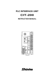
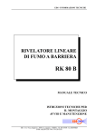
1.0 GENERAL
The unit is a highly accurate and stable digital process indicator that
accepts all commonly used process signals. The unit can be used
"stand alone" or, with the Modbus serial communications pod option,
as part of a larger system.
The diagram shows the rear panel positions for all electrical connections.
THIS SECTION FOR USE BY COMPETENT PERSONNEL ONLY
OPTION POD SLOT 2
(NOT SHOWN)
3.1 Safety Information
OPTION POD SLOT 1
The case design enables option Pods to be easily installed without
the need for dismantling or re-calibration. A range of Pods are
available for:
Relay outputs
Isolated 4-20 mA re-transmission
Modbus serial communication.
FRONT PANEL
SEALED TO IP65
BRIGHT FOUR
DIGIT DISPLAY
1
2
o
SHIFT
KEY
INCREMENT
KEY
WARNING
READ SAFETY INFORMATION BELOW
BEFORE INSTALLATION
WARNING
Hazardous voltages may be present on
the terminals - the equipment must be
installed by suitably qualified personnel and
mounted in an enclosure providing protection
to at least IP20.
ISOLATION
The power supply terminals and associated
internal circuitry are isolated from all other
parts of the equipment in accordance with
BS EN61010-1 for connection to a Category
II supply (pollution degree 2)
Functional isolation (500v max) is provided
between input and output circuits, and between
inputs and communications (where fitted).
Any terminals or wiring connected to the
input, output or communications terminals
which are accessible in normal operation
must ONLY be connected to signals
complying with the requirements for Safety
extra low voltage (SELV) circuits.
DISCRETE LED
ALARM INDICATORS
PROCESS
INPUT
CYCLE
KEY
3.0 INSTALLATION
3
C
POWER
CONNECTOR
2.0 UNPACKING
Please inspect the instrument carefully for any signs of shipping
damage. The packaging has been designed to afford maximum
protection, however, we cannot guarantee that mishandling will not
have damaged the instrument. In the case of this unlikely event,
please contact your supplier immediately and retain the packaging
for subsequent inspection.
4
Tag No.
LEGEND
WINDOW
3.2 Installing Into a Panel
WARNING
If not installed in accordance with these
instructions, protection against electrical
hazards may be impaired.
Installation overvoltage category - 2 (as per BS EN61010-1)
The Mains supply to the equipment must be protected by an
external 1 Amp fuse and a suitable switch or circuit breaker
which should be near the equipment.
The equipment contains no user serviceable parts.
The Mains supply to the equipment must be protected by an
external 1 Amp fuse and a suitable switch or circuit breaker
which should be near the equipment.
140.0
10 mm MAX PANEL THICKNESS
DM3420 SERIES
INTELLIGENT
PROCESS
INDICATOR
OPTION POD
CLAMPING SCREW
PANEL CLAMP
Cutout 92.0/92.8 x 45.0/45.6 mm (DIN 43700)
(+) L
N (-)
Refer to section 8.0 for Mechanical Detail.
The maximum panel thickness is 10mm. The instrument case has an
integral gasket which forms a seal when the instrument is tightened
against the panel. The panel should be clean, smooth and at least
1.6mm thick for the seal to be effective.
WARNING
Use only the retaining screws provided to
clamp the instrument to the panel (screws
must be tightened sufficiently to effect a seal
but must never be overtightened).
Wires are retained by screws. Ensure that the exposed section of
the wire is fully inserted and that no loose strands are exposed.
3.5 Sensor Connections
All sensor connections are made via the five way "fast wiring" socket
at the rear of the unit (wire size 0.5 to 1.5mm²).
1
2
Installation should be undertaken in accordance with relevant
sections of BS6739 - British Standards code of practice for
"Instrumentation in Process Control Systems: Installation
design and practice".
3.5.2 Current Measurement of an Externally Powered Loop
1
2
-
+
1
2
-
Tx
Issue: 4
A 24V internal power supply is available to power external field transmitters.
To make a connection: Insert small screwdriver blade into tension
clamp orifice, (1) push and twist to deflect clamp into open position.
Do not lever screwdriver thus forcing connector body sideways.
Insert conductor tail sufficiently into (2) then release screwdriver.
Ensure no loose wire strands protrude.
4.3 Entering Menu Mode
The Root Menu mode is accessed from "Run" by pressing ENTER
(B&C) followed by CYCLE (A). The display will now show "inPt". In
order to understand what this means, the following diagram shows
where we are within the basic Root menu.
ROOT MENU
4.0 PROGRAMMING THE INSTRUMENT
The unit is a microprocessor based instrument enabling it to satisfy
a variety of applications. All programming is available from the front
panel or via a PC using the RS485 Modbus communications pod.
INPUT
ESCAPE
CYCLE
0 - 1 Volts
B
B
OUTPUT
SYSTEM
POD 1
POD 2
SUBMENU
SUBMENU
4.3.1 Moving Around The Menu
You can browse through the Root menu by pressing CYCLE (A)
which moves the menu position from left to right (after reaching SYS,
the menu position wraps around to the start).
4.3.2 Entering A Submenu
To enter a submenu, first cycle around the Root menu until the
required submenu is displayed. For the purposes of this tutorial
press the CYCLE (A) key until InPt is displayed. Pressing SHIFT (B)
enters the Input Submenu. tYPe will now be displayed. The diagram
shows our position in relation to other items in the menu.
Pressing CYCLE (A) moves left to right, wrapping around at the end.
The unit alters items in the menu list depending upon settings made.
InPt
tYPE
dP
r ngE
Lo
Short Menu
C
CLEAR
INC
A
SYS
SUBMENU
ENTER
SHIFT
B
C
OUTPUT
SLt2 *
* Slot menus only appear when respective option pods are fitted.
CYCLE (A), SHIFT (B) and INC (C) keys are pressed singularly.
ESCAPE (A&B), ENTER (B&C) and CLEAR (A&C) are obtained by
simultaneously pressing the two keys.
A
SLt1 *
inPt
SUBMENU
4.2 Key Definitions
All programming is done using the three front panel keys, A,B and
C are shown to assist the tutorial.
A
0 - 10 Volts
1 - 5 Volts
Every effort has been taken to ensure the accuracy of this
specification, however we do not accept responsibility for
damage, injury, loss or expense resulting from errors and
omissions, and we reserve the right of amendment without
notice.
Stock code : 52-314-2246-02
RUN is the principal mode of operation, which displays the Process
Variable from which all other modes are accessed. The unit will
always time-out back to this mode after one minute.
MENU mode provides access to the programmable parameters.
EDIT mode is entered from Menu Mode and allows the user to
inspect and modify a parameter.
3.5.3 Voltage Connection
+ +
Current retu
4-20mA
0-20mA
0-10mA
4.1 Programming Guide
The unit has three operating modes. These are :RUN (DISPLAYS PROCESS VARIABLE)
MENU
EDIT
4-20mA
0-20mA
0-10mA
Green Lane. Tewkesbury.
Gloucestershire. GL20 8DE. UK
Telephone : 01684 296818.
Fax : 01684 293746.
Email: [email protected]
3.5.1 Current Measurement of an Internally Powered Loop
3.3 Wiring
All connections are made to sockets which are removable for ease
of maintenance.
3.4 Power Supply
The Power supply rating will be indicated on the top of the instrument,
ensure it is correct for the application.
Designed, manufactured and supported by :
C
FiLt
Lin
Full Menu
Hi
4.3.3 Editing A Parameter
The items displayed in the menu can either be submenus, parameters
or numbers, most of the items in the Inputs menu are parameters
which can be edited.
The Root menu, as its name suggests is not a submenu. Pressing
the ESCAPE (A&B) key sequence whilst in the Root menu will take
the user out of Menu mode and into Run mode. Thus the process
variable will be shown on the display. Refer to section 5.2 if an error
code is shown after programming in menu mode.
Press the CYCLE (A) key until tYPe is displayed, then press SHIFT (B).
4.4 The Menus
4.4.1 The INPt (INPUT) Submenu
The INPt submenu is used to program all the characteristics of the
input sensor and any signal conditioning that may be required. The
selection of an option in the list may affect items further down.
Therefore, during programming, the user should start at the top of
the menu and work down, to avoid setting an option which may later
become obsolete. Short menu only items shown in bold.
The current setting will now be shown flashing. This item is
changed by pressing the INC (C) key.
The choice of options available is as follows:
inPt
TITLE
tYPE
dP
rngE
rngE
Lo
Hi
Lin
FiLt
uSEr
tYPE
crnt
VoLt
Press the INC (C) key until "crnt" is displayed.
Note that whilst the display is flashing, the option on the display has
not been saved to memory. To select an option, the ENTER key
sequence is used. Press ENTER (B&C). The display will stop flashing
momentarily before returning to Menu mode. The system automatically
steps on to the next entry to speed the process of programming. This
method of editing parameters is repeated throughout the menu structure.
4.3.4 Returning From Submenus
To return up from the inPt menu to the root menu wait for 1 minute
or press the ESCAPE (A&B) key.
Pressing the ESCAPE key from our current position in the Inputs
submenu takes us back to the Root menu. The menu position will
automatically step to the next menu item, if no pods are fitted the unit
will show SYS, if pods are fitted SLt1 or SLt2 will be shown.
6.0 SPECIFICATION @20 ºC
6.1 Process Specification
DC VoltageRange
Accuracy
Thermal Drift
DC CurrentRange
Input Impedance
Accuracy
Thermal Drift
Excitation
0-1 volts / 1-5 volts / 0-10 volts
0.05% FS
Zero 0.1µV / ºC Span 100 ppm /ºC
0-20mA / 4-20mA / 0-10mA
47 ohm (current) 1 Mohm (voltage)
0.05% FS
100 ppm / ºC
24V ±5% @ 50 mA
6.2 General Specification @ 20 ºC
Input/Output Isolation
500VAC rms (galvanically isolated)
Update time
250 mS maximum
Time Constant (Filter off)
<1 second (to 63% of final value)
Filter Factor
Off, 2 Seconds,
10 Seconds or Adaptive
Warm-up time
2 minutes to full accuracy
Display Range
-999 to 9999
Power Supply
S1
90-253 VAC 50/60 Hz
S2
20-35 VDC
Power Consumption
6VA Maximum (options fitted)
Environmental
Sealing to PANEL
IP65
Ambient Operating Range - Non UL: -30 to +60 ºC
UL: -30 to +40°C
Ambient Storage Temperature
-50 to +85 ºC
Ambient Humidity Range
10 to 90% RH non condensing
Approvals
EMC
BS EN61326
Electrical Safety
BS EN61010-1
Environmental Approvals for Tension Clamp Terminals
Low Temperature
IEC 68-2-1
Dry Heat
IEC 512-6-9
Damp Heat
IEC 512 -6-3
OPTIONS
crnt, VoLt
888.8, 88.88, 8.888, 8888
4-20, 0-20, 0-10
1-5, 0-1, 0-10
000.0
100.0
nonE, Sqrt, cust
nonE, 2.5s, 10s, Adaptive
in 0........ in 9 out 0..........out 9
DETAIL
Set Current or Voltage
Defines decimal point location
mA range setting, only for Current input
Voltage setting, only for Voltage input
Low engineering range, -999 to 9999
High engineering range, -999 to 9999
Linearity: none, square root or custom *
Input filtering or smoothing
User Linearisation
Selecting "cuSt" in the "Lin" parameter allows access to the "uSEr"
submenu. Within this menu, 10 points may be programmed to relate
electrical input to engineering value. These points are represented by "IN"
and "OUT" entries within the menu, where "IN" are the electrical inputs
and "OUT" the resultant engineering value. The entries for the electrical
input must progressively increase. Inserting an electrical value less
than the previous electrical value will mark the end of the interpolation.
Any value falling outside the bounds specified by the table will be regarded
as out of bounds and under or over range will be displayed.
Peak/Valley Display
The max and min process variables measured since switch-on or last
reset are continuously calculated within the instrument. To view peak,
press "shift", to view valley, press "INC". Peak and Valley can be
reset by pressing "CYCLE",
Damp Heat cyclical
Salt Spray
Sulphur Dioxide
Hydrogen Sulphide
Gas Tightness
IEC
IEC
IEC
IEC
IEC
68-2-30
512-6-6
68-2-46
68-2-16
512-Pr.11n
4.4.2 The SyS (System) Submenu
TITLE
LiSt
cLEn
SPEn
Adel
PASS
oFFS
OPTIONS
DETAIL
FuLL, SHrt
Selects full or short menu
oFF, on
Clear enable (option pods)
oFF, on
Setpoint enable (option pods)
oFF, 2,5,10,20,60,120,240 Power-up alarm delay
4 digit passcode
Modify any password code
User defined offset
Take care when replacing sensor
Refer to section 7.0 for SLt menu structures.
5.0 OPERATION
5.1 Run Mode Operation
The normal display shown in this mode is the process variable.
ACTION
View setpoints (Adjust value if SPEn enabled)
Clear latched alarms (cLEn enabled)
KEYPRESS
CYCLE (A)
CLEAR (A&C)
5.2 Failure Modes
If the input is outside the measuring range of the instrument, the
following error messages will be shown.
Input
Display
Over range *
----
PV > 110% Eng. Span
----
PV < Eng. Low (1.25% Eng. Span)
Under range *
Condition
* If the instrument is programmed with a custom linearisation the
instrument will display over or under when the input falls outside
the linearisation bounds. If a small amount of valid signal over/under
range is required, this must be built into the linearisation table.
Hysteresis Operation
HIGH ALARM
Setpoint
LOW ALARM
Hysteresis
Band
Hysteresis
Band
Setpoint
7.0 OPTION PODS
7.0.1 Installing Pods
Power must be removed from unit before adding/removing a pod.
Alarm State
Slot 1 (alarm 1 and 2) should be positioned on the left side of the
unit looking from the front to correspond to front panel alarm indicator,
slot 2 (alarm 3 and 4) is positioned on the right.
To install an option pod, slide back the cover to its next engaging
position and push the pod connection within the mating connector.
To remove an option pod, disengage the supporting latch situated
beneath the pod by pushing the back cover forward, the pod can
then be lifted away from the instrument connector.
The relay pod has two "change over"
relays with a common wiper.
1
2
3
4
5
NC = Normally closed
NO = Normally open
7.1.1 SLT1, SLT2 (Relay Pod) Submenu
Each relay can be set as high or low alarm independently.
TITLE
AL 1
SEt1
dEL1
HYS1
LAt1
inUI
OPTIONS
Hi, Lo
User defined
oFF,2,5,10,20,60,120,240
User defined
oFF, on
oFF, on
DETAIL
Alarm action
PV at which the alarm triggers
Alarm delay (seconds)
Hysterisis band (see below)
Sets latching to on or off
Invert relay operation
Alarm State
7.1.2 Relay Specification
AC
DC
Maximum Load
5A @ 250V
5A @ 30V
Maximum Power
1750VA
210W
Maximum Switching
250V
125V
Electrical Life
105 operations at rated load
Mechanical Life
50 Million operations
7.2 Isolated 4-20mA Re-transmission Pod. POD-3000/03
-
7.1 Dual Relay Pod. POD-3000/02
R Load
V
+
R Load
1
2
3
4
5
1
2
3
4
5
The re-transmission pod (when fitted) is designed to provide
0-10mA, 0-20mA or 4-20mA output in active or passive modes. The
output can be any portion of the display. The pod can be used in two
modes:
Active (Source)
Passive (Sink)
Max RLoad = 1K
Note:
RLoad < (V-2) K Ohm
22
And Vmax = 30V
Only one Re-transmission pod can be fitted.
Continues through for Relays 2 - 4 (when fitted).
7.2.1 SLT1, SLT2 (Re-transmission Pod) Submenu
7.3.1 SLT1, SLT2 (Communications) Submenu
TITLE
Lo 1
Hi 1
SPAn
TITLE
Addr
baud
Line
OPTIONS
User defined
User defined
4-20mA, 0-20mA, 0-10mA
and "INC" simultaneously when "cLEn" is set to "ON" within the
"SYS" menu
DETAIL
Low span range
High span range
User defined output current
7.2.2 Re-Transmission Pod Specification
Minimum Current Output
> 0mA
Maximum Current Output
< 23mA
Accuracy
0.07% or 5µA, which ever is greater
Maximum External Power Supply 30V (passive mode)
Voltage Effect
0.2µA / V
Ripple Current
<3µA
Isolation
500V AC
Temperature Stability
1µA / ºC
7.3 Modbus Serial Communications Pod. POD-3000/05
The diagram below shows a PC connected to Modbus pods.
OPTIONS
User defined
9.6, 19.2
2, 4
96.0
DETAIL
Instrument device number
User selected baud rate
4 Wire or 2 wire half duplex RS 485
7.3.2 Comms Pod Specification
Configuration, system I/O and display unit PC communication.
Physical Layer
4 wire or 2 wire half duplex RS485
Isolation
500V AC
Maximum Fan out
32 units
Software Baud Rate
19,200 or 9,600
Protocol
Modbus RTU format
1
o
2
C
3
4
48.0
Tag No.
* Optional link
11.0
1
2
3
4
131.0 BEHIND BEZEL
5
Modbus link
* Connection of the link connects a 100 ohm termination resistor
across pins 4 and 5. This resistor should only be selected for the
instrument furthest away from the host. Full details of the modbus
protocol are supplied separately with the pod.
8.0 MECHANICAL DETAIL
Device 1
Device 2
Device 3
LINK, Device 4
Material
Weight
Flammability
Pod weight
Panel cutout
ABS/PC
200
IEC707 FV0
40g typical
92mm x 45mm
Stock code : 52-314-2246-02, Issue: 4