1
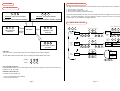
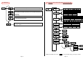
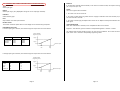
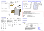
INDEX
MEDACS Universal & Frequency
Status Instruments Ltd, Green Lane Business Park, Tewkesbury, Glos. GL20 8DE
Tel: +44 (0)1684 296818
Email: [email protected]
Fax: +44 (0)1684 293746
Web: www.status.co.uk
52-214-2405-01 Issue: Web
SECTION
CONTENTS
PAGE NO.
1.0
2.0
3.0
4.0
5.0
6.0
7.0
8.0
9.0
10.0
11.0
12.0
13.0
14.0
DESCRIPTION
UNPACKING
SPECIFICATION
INSTALLATION
WIRING
INPUT/OUTPUT CONNECTIONS
PROGRAMMING
OPERATION
GENERAL MENU NAVIGATION
INPUT MENU STRUCTURE
OUTPUT MENU STRUCTURE
SYSTEM MENU STRUCTURE
SERIAL COMMUNICATIONS
ENABLING MULTI DROP COMMS
1
1
1-4
4-5
5-6
6-9
9-10
11
12-13
14-19
19-21
22-23
24
24
3.1 INPUTS
1.0 DESCRIPTION
The MEDACS 2XXX series is a range of DIN rail transmitters with a wide range of options available. This manual
documents the functionality of the MEDACS 21XX, 22XX, 23XX and 24XX. The units are available with the
following output option combinations:
PART No.
2122
2113
2133
2211
2222
2233
2213
2322
2313
2333
2411
2413
2422
2433
INPUT
U
U
U
U
U
U
U
F
F
F
F
F
F
F
O/P 1
C/O relay
Current (4
Twin relay
Current (4
C/O relay
Twin relay
Current (4
C/O relay
Current (4
Twin relay
Current (4
Current (4
C/O relay
Twin relay
to 20) mA, (0 to 10)mA, (0 to 20)mA
to 20) mA
to 20) mA
to 20) mA, (0 to 10)mA, (0 to 20) mA
to 20) mA
to 20) mA
O/P 2
C/O relay
Twin relay
Twin relay
Current (4 to 20) mA
C/O relay
Twin relay
Twin relay
C/O relay
Twin relay
Twin relay
Current (4 to 20) mA
Twin relay
C/O relay
Twin relay
The units' performance is enhanced by the inclusion of Status' own TFML (Transfer Function Module Library).
TFML was designed to make the transmitters' signal processing capabilities as flexible as possible. TFML is
not documented in detail in this manual. Please contact your supplier for further information.
2.0 UNPACKING
Please inspect the instrument carefully for any signs of shipping damage. The packaging has been designed
to provide maximum protection, however we cannot guarantee that mishandling will not have damaged the
instrument. In the case of this unlikely event, please contact your supplier immediately and retain the
packaging for subsequent inspection.
3.0 SPECIFICATION
EMC Approval
Immunity
Emissions
Supply
Ambient
EN61326: 1997
Annex A Industrial
Class A
24 V ± 10 % DC @ 200 mA maximum per unit
(-30 to 60) °C
Care must be taken when installing units into an enclosure to ensure that the above ambient range is not
exceeded. Power supply units can produce heat and if possible are best mounted in a separate enclosure
away from the MEDACS units.
3.1.1 UNIVERSAL INPUT 21XX AND 22XX ONLY
SENSOR
mA
RTD
T/C
Volts
RANGE
4 to 20, ± 20, ± 10
Pt100, Ni120
K, J, T, R, S, E, N, L, B
± 0.1, ± 10, ± 1, ± 5, 1 to 5 slidewire
CURRENT INPUT
Base Accuracy
Thermal Drift
Input Impedance
Linearisation
0.05 % FS ± 0.05 % of reading
0.02 %/°C
20 Ω
Linear, Square root, Power 3/2, Power 5/2, Custom
Two isolated and regulated 19 V power supply's are available to power the current loops, and are capable
of sourcing 25 mA for each channel.
RTD
Sensor Range
Linearisation
Basic Accuracy
Thermal Drift Zero
Span
Excitation Current
Lead Resistance Effect
Max. Lead Resistance
(-200 to 850) °C
BS EN 60751/JISC 1604/Custom
0.1°C ± 0.05 % of reading
± 0.004 Ω/°C
0.01 % /°C
1 mA
0.002 °C/Ω
50 W/leg
THERMOCOUPLE TYPE
K
J
T
R*¹
S*¹
E
L
N
B*²
Custom
RANGE (°C)
-200 to 1370
-200 to 1200
-210 to 400
-10 to 1760
-10 to 1760
-200 to 1000
-100 to 600
-180 to 1300
-10 to 1650
-1999 to 9999
Accuracy
Linearisation
Cold junction error
Cold junction tracking
Cold junction range
Thermal drift Zero
Span
± 0.04 % FS ± 0.04 % reading or ± 0.5 °C, whichever is greater
BS4937/IEC 584-3/Custom
± 0.5 °C
0.05 °C/°C
(-20 to 70) °C
4 µV/°C
0.02 % /°C
*NOTES:
1. Accuracy true for (800 to 1760) °C
2. Accuracy true for (400 to 1650) °C
Page 1
Page 2
VOLTAGE INPUT
Range
Accuracy
Thermal drift
Input impedance
Linearisation
*Slidewire
± 100 mV, ± 1 V, ± 5 V, ± 10 V, (1 to 5) V
0.04 % FS ± 0.04 % of reading
0.02 %/°C
1 MΩ
Linear, Square root, Power 3/2, Power 5/2, Custom
3 wire Potentiometer inputs can be accommodated between 50 Ω and 10 KΩ
RELAY OUTPUTS
Two relay options are available, either a single changeover or twin independent relays with normally closed
contacts.*¹
Alarm Action
Hysteresis
Delay Time*²
Start-up Delay
Off, High, Low, Deviation, Test
Programmable (0 to 100) %
Programmable
Programmable
Max. Switching Voltage
Max. Current
Max. Power
Contact Resistance
Operate Time
Electrical Life @ Full Load
Mechanical Life
AC
DC
48 V RMS
48 V
1 A @ 48 V
1 A @ 30 V
60 VA
30 W
< 100 mΩ
< 5 ms
100 000 operations
10 000 000 operations
3.1.2 FREQUENCY INPUTS 23XX AND 24XX ONLY
A wide range of input types and frequencies can be accommodated without the need for Switches or
Jumpers. Totalise functions are a standard feature on the single channel version and are stored during
power down.
Input Types
Frequency range
Accuracy
Namur, Low Voltage (> 10 mV), TTL, Open Collector, PFC
0.1 Hz to 20 kHz.
0.003% FS
DIGITAL INPUTS 21XX AND 23XX ONLY
Single channel units can also accept two external digital inputs which can be TTL, Open Collector, 24 VDC
Logic or Potential Free Contacts. Dig 1 is dedicated to a reset/clear function enabled by the configuration
software whilst Dig 2 is reserved for use with TFML. Both digitals can be read via the communications and
used to signal events.
OUTPUTS
Two output option types are available per channel, relay or current re-transmission. The configuration of
these will vary depending upon whether they are fitted on the single or dual channel transmitter.
CURRENT RE-TRANSMISSION
Output Range
Single Channel
Dual Channel
Max. Current Output
Accuracy
Max Power Supply
Temperature Stability
OUTPUTS
(0 to 10) mA, (0 to 20) mA, (4 to 20) mA source or sink
(4 to 20) mA sink
< 23 mA
0.07 % or 5 mA, whichever is greater
30 V (In SINK mode)
5 µA/°C
*NOTE: Maximum source load 750 R
*NOTES:
1. Contacts are normally closed i.e the contact is closed at power off and when operating in an alarm
condition. The contact opens in the absence of an alarm condition. The active function can be reversed
in software.
2. Alarm must be continuously present for this period in order to be recognised
3.2 GENERAL
Response Time
Filter
Power Requirements
Breakdown Isolation
Ambient Operating Range
Ambient Storage
Ambient Humidity
EMC Emissions
EMC Immunity
Display Range
300 ms
Programmable or Adaptive
24 VDC ± 10 % @ 200 mA
1 kV I/P~O/P~PSU
(-30 to 60) °C
(-50 to 85) °C
(10 to 90) % RH
BS EN61326
BS EN61326
-1999 to 9999
4.0 INSTALLATION
THIS SECTION FOR USE BY COMPETENT PERSONNEL ONLY
SAFETY INFORMATION
WARNING!
THE EQUIPMENT MUST BE INSTALLED BY SUITABLY QUALIFIED PERSONNEL AND
MOUNTED IN AN ENCLOSURE PROVIDING PROTECTION TO AT LEAST IP20. THE
EQUIPMENT CONTAINS NO USER SERVICEABLE PARTS.
4.1 ISOLATION
The 24 VDC power supply and RS485 comms bus share the same common connections. Isolation is provided
between input, output and supply/comms breakdown isolation voltage 500 VAC RMS flash tested to 1 kVDC.
Page 3
Page 4
4.2 INSTALLATION DETAIL DIAGRAM
OUTPUTS
BUS
JUMPER
5.2 POWER/COMMS CONNECTIONS
BUS
JUMPER
55.0 mm
35.0 mm
BUS
JUMPER
Ensure that the power supply is correct for the application. Over voltage could damage the instrument.
Ensure that the exposed section of the wire is fully inserted and that no loose strands are exposed.
44.0 mm
6.0 INPUT / OUTPUT CONNECTIONS
6.1.1 FREQUENCY INPUT CONNECTIONS WIRING DIAGRAM
55.0 mm
86.0 mm
SINGLE CHANNEL UNIT
DUAL CHANNEL UNIT
53.0 mm
INPUT
CONNECTOR
INPUTS
1
2
3
4
5
CH1
CLIP - PULL TO RELEASE UNIT
SINGLE CHANNEL
UNIT
1
4 5
8
1
8
1
4 5
6
7
1
2 3 4
5
6
7 8
1 2 3
4 5
6
7
8
3
4
5
6
7
8
DISCRETES
1
4
1
4
4
2
TTL
TTL
4 5
6
7
3
8
4
mV
mV
+mV-
Page 5
2
NPN
1 2 3
‘BUS JUMPER’
5
PNP
5.1 WIRING-UP MULTIPLE UNITS
Wires to Power and
communications to
one connector are
‘Bussed’ to all.
4
6
7
8
8
NPN
MEDACS is provided with a unique ‘BUS JUMPER’ system for quick wiring of COMMS and POWER connections.
To use the Bus Jumper, disconnect all power supply/comms connectors and place them so that they
connect between the two units. Wiring to one connector then connects to all units.
3
NAMUR INPUT
PNP
All connections are made to sockets which are removable for ease of maintenance. Installation should be
undertaken in accordance with relevant sections of BS6739 - British Standards Code of Practice for
"Instrumentation in Process Control Systems: Installation Design and Practice".
2
CH1
NAMUR
INPUT
1 2 3
5.0 WIRING
7
CH2
+mV-
+mV-
Page 6
(5 to 24) V
DIS 2
DUAL CHANNEL
UNIT
6
DIS 1
INPUTS
58.6 mm
A separate
power supply is
required for
discretes if
isolation is to
be maintained
6.2 OUTPUT CONNECTIONS WIRING DIAGRAM
2 N/C Relays*²
3
4
5
2
7
1
8
CH2
CH1
1
6
3
5
6
2
3
4
1
7
2
5
6
7
8
O/P 2
3
5
+
6
-
7
+
8
-
RTD
O/P 1
6
-
+
2
8
2
-
+
4
6
-
+
4
(5 to 24) V
THERMOCOUPLE
THERMOCOUPLE
2
-
+
8
VOLTAGE
-
+
4
V
VOLTAGE
V
CURRENT ACTIVE
(Externally powered)
1
CURRENT PASSIVE
(Using MEDACS
internal power)
3
4
7
8
+
-
+
-
3
TX
+
V
-
7
5
TX
+
3
4
+
-
CURRENT ACTIVE
(Externally powered)
1
CURRENT PASSIVE
(Using MEDACS
internal power)
-
A separate
power supply
is required for
discretes if
isolation is to
be maintained
3
3
4
4
5
5
5
-
6
6
7
7
8
8
6
7
8
TYPE: XX11
TYPE: XX22
Re-transmitted
Current Passive
Output
Changeover
Relays*¹
Pins 1+2, 3+4, 5+6,
7+8 are
connected together
internally.
1
RLY B
2
3
RLY A
4
RLY B
RLY B
RLY A
RLY A
Passive
5
RLY B
-
6
-
7
RLY A
8
TYPE: XX33
Active
TYPE: 2113,2313
ALARM
STATE
IN ALARM
NOT IN ALARM
SETTING
NINV
INV
Power Off
8 and 7/4 and 3
8 and 6/4 and 2
8 and 7/4 and 3
8 and 6/4 and 2
8 and 7/4 and 3
8 and 7/4 and 3
*² Normally closed relays
ALARM
STATE
IN ALARM
NOT IN ALARM
SETTING
NINV
INV
Power Off
Page 7
2
4
5
-
6
7
8
TYPE: 2213,
2413
2 N/C Relays*² Re-transmitted Current
+19 V to Power Loop Re-transmitted
Current
on PIN 8
Passive Output
NOTE: ‘Active’ is when
MEDACS powers current loop. ‘Passive’ is
when external device
powers loop.
*¹ Changeover relays
-
1
3
3
TX
+
DIS 2
-
+
4
DIS 1
2
-
2
4
3
DISCRETES
CH1
RTD
1
2
2 N/C Relays*²
+
2
2
+
1
1
1
+
INPUT
CONNECTOR
+
SINGLE CHANNEL UNIT
DUAL CHANNEL UNIT
+
6.1.2 UNIVERSAL INPUT CONNECTIONS WIRING DIAGRAM
Relay Closed
Relay Open
Relay Closed
Relay Open
Relay Closed
Relay Closed
Page 8
6.3 POWER SUPPLY/COMMS WIRING DIAGRAM
7.2 KEY PRESS DEFINITIONS
Each key pressed
individually produces
the following menu
action (shaded
circle signifies key
pressed):
“BUS JUMPER”
RX+
RX-
TX+
TX- POWER GND
R
G
B
CYCLE
R
G
B
SHIFT
R
G
B
INC
Keys pressed
simultaneously produce
the following menu
actions (shaded
circle signifies key
pressed):
R
G
B
ESCAPE
R
G
B
ENTER
R
G
B
CLEAR
Each MEDACS unit has 3 keys (RED, GREEN and BLUE) to enable menu programming.
7.3 ENTERING MENU MODE
On power up, the unit will take a few seconds to configure itself. Run mode will then automatically be
entered. Menu mode is accessed from run mode by pressing ENTER followed quickly by CYCLE. The user
will then be able to move around the root menu.
7.0 PROGRAMMING THE INSTRUMENT
The unit is a microprocessor based instrument enabling it to satisfy a variety of applications. For single
channel units, a display/keypad allows local menu programming from the front panel. For single or dual
channel units, programming is available via a PC using the RS485 Modbus communications utility.
NAVIGATING AROUND THE MENU
The user can navigate around the root menu (or any submenu) by pressing CYCLE. Menu navigation wraps
around at the end of the menu list. The items displayed in the menu can either be submenus, parameter
lists or numbers.
ENTERING A SUBMENU
Pressing SHIFT enters the submenu or enables parameter list/number editing, depending on where the
menu structure is currently being pointed. If the menu navigation is pointing at a submenu, the subsequent
submenu can then be cycled around by pressing CYCLE.
7.1 MENU PROGRAMMING
OPERATING MODES
The MEDACS has 3 operating modes. These are:
7.4 EDITING A PARAMETER LIST
RUN MODE - Process Variable (PV) is displayed.
MENU MODE - Enables navigation around menu structure.
EDIT MODE - Enables menu parameters to be edited.
Run mode is the principal mode of operation. The other two modes are accessed as shown in the diagram
below.
RUN MODE
ENTER then CYCLE
ESCAPE
MENU MODE
SHIFT
ESCAPE or ENTER
EDIT MODE
A parameter is selected from a list of options. The parameter option list can be cycled through by pressing
INC. The user will be able to distinguish between a menu cycle action, and a parameter list cycle action
by having the following 2 dynamic display styles:
ACTION
Menu cycle
Parameter list cycle
DISPLAY STYLE
Display changes on cycle press, no flash
Display flashes
EDITING A NUMBER
A number is edited by incrementing each digit in turn. The user will know which digit is currently selected
for incrementing by the flashing digit. Pressing INC will increment the digit. On overflow, the digit will
wrap around to '-', ‘-1’ or '0', whichever is applicable. Pressing SHIFT will shift the currently selected digit
right one place. If the number is a whole number, pressing SHIFT when the right most digit is selected will
wrap the selection around to the left most digit, and the process starts again.
If the number has a decimal point (DP), pressing SHIFT when the right most digit is selected will select the
decimal point position as the editable parameter. In this case, pressing INC will shift the DP position one
place to the right. If the current DP position is the right most, the DP will wrap around to the first DP position. Pressing SHIFT will select the left most digit as the editable parameter, and the process starts again.
While the display is flashing, the number/option on the display has not been saved to memory. When the
desired number is in view, pressing ENTER will save it to memory. The display will stop flashing for 1 s to
confirm the saved number, before returning to the previous submenu. Waiting for 60 s without a key press,
or pressing ESCAPE will return the user to the previous submenu, without saving the number.
Page 9
Page 10
9.0 GENERAL MENU NAVIGATION
8.0 OPERATION
The diagram overleaf details how to move around the menu structure and enter data and shows:
8.1 RUN MODE OPTIONS
R
G
1. How to enter a real number
2. How to choose an option from a list
3. How to enter and navigate around a submenu
B
R
G
B
UNIVERSAL SHOW VALLEY READING
UNIVERSAL SHOW PEAK READING
FREQUENCY SHOW FREQUENCY READING
FREQUENCY SHOW SECONDARY VARIABLE READING
Using these three procedures the user can enter all applicable data to configure the unit to suit the application. The options displayed in the menu depend on whether the short menu or full menu option are
enabled. (This can be selected in the sys submenu).
9.1 GENERAL MENU STRUCTURE
R
G
B
G
B
RUN MODE
ESCAPE
PERFORM CLEAR
FUNCTION
FR
EDIT SETPOINTS
SHORTCUT
R
R
G
SHIFT INTO EDITABLE VALUES
B
SHIFT INTO EDITABLE VALUES
CYCLE AROUND MENU ITEMS
EQ
1. ENTER
REAL
NUMBER
R
G
R
Itn1
DESCRIPTION
ENTER VALUE
UE
R
G
OR
B
NC
Y
ENTER TO ACCEPT CHANGE
ON
LY
R
G
B
SHOW UPPER 4 DIGITS
OF TOTAL
2. CHOOSE
FROM
OPTION
LIST
R
G
B
G
INC TO
INCREMENT
CHOICE
B
OR
G
R
G
B
R
G
B
ESCAPE TO REJECT CHANGE
Itn2
DESCRIPTION
R
B
R
ENTER TO ACCEPT CHANGE
G
OptA
OptB
DESCRIPTION A
DESCRIPTION B
B
ESCAPE TO REJECT CHANGE
SHIFT INTO SUBMENU
RUN MODE
This is the normal run time mode where the PV is displayed to the chosen resolution.
To enter MENU mode from RUN mode, the user should press ENTER followed by CYCLE.
ENTER =
CYCLE =
R
R
G
G
B
3. ENTER
SUBMENU
R
G
B
R
G
B
It3A
DESCRIPTION 3A
Itn3
DESCRIPTION
It3B
DESCRIPTION 3B
ESCAPE TO EXIT SUBMENU
R
G
B
CYCLE AROUND MENU ITEMS
B
EDIT SETPOINTS SHORTCUT
If enabled (EnbL submenu), and if relay output card is fitted, this menu gives access to the relevant alarm
setpoints, 1A, 1B, 2A and 2B.
PERFORM CLEAR FUNCTION
If enabled, pressing CLEAR will:
1. Clear the stored Peak/Valley readings
2. Clear any latched alarms
Page 11
B
1234
INC TO
INCREMENT
DIGIT
SHIFT INTO OPTION LIST
R
G
B
Page 12
10.0 UNIVERSAL INPUT MENU STRUCTURE 21XX AND 22XX ONLY
9.2 MENU MAP
START
InPt
The input submenu is where the input to the unit is selected and configured
InPt
OUt1
OUt2
Output configures the outputs of the unit. The format of the output submenu
varies according to the output options fitted. The two possible output types are:
type
Type
tc
Thermocouple
rtd
RTD
0.1
(0 to 100) mV
rnge
Range
mA Output
Relay output
4-2
20
(4 to 20) mA
none
None Linear
SYS
This submenu configures the units system characteristics
e.g communications and passcode
lin
Linearity
j
J
If a TFML module is loaded, this submenu gives access to the 8 TFML
configuration modules
UNIT
Unit
888.8
1 DP
enlo
Engineering low
Enter value
enhi
Engineering high
Enter value
filt
Filter
ULI n
User linearisation
s9rt
Square Root
T
T
hi
High
5
±5V
1-5
5
(1 to 5) V
rt32
Power3/2
n120
Ni120
R
R
uolt
Voltage
10
± 10 mA
S
S
rt52
Power5/2
user
User defined
jisc
Pt100 Japanese/USA
user
User Defined
E
E
de9c
Degree C
dp
Decimal Place
burn
Burnout
1
±1V
20
± 20 mA
p100
Pt100 European
CA
K
tFnL
10
± 10 V
crnt
Current
F
F
N
N
B
B
de9F
Degree F
88.88
2 DP
8.888
3 DP
8888
0 DP
lo
Low
Enter value
SE9S
Segments
Enter value
entr
Enter
In1
Input 1
Enter value
OUt1
Output 1
Enter value
Etc.
NOTE: that shaded menu entries
Page 13
user
User Defined
are only available if FULL menu type is chosen.
Page 14
BURNOUT
If TC/RTD input selected. Defines whether, in the event of a sensor burnout, the output current goes high
(21.5 mA) or low (3.6 mA).
10.1 UNIVERSAL INPUT MENU FUNCTION BLOCKS 21XX AND 22XX ONLY
TYPE
Select input type.
FILTER
There are 3 types of filter available:
RANGE
Select input range. (Only displayed if voltage or current input type selected).
1. Set value to 0.1 to turn filter off.
LINEARITY
Choose linearity type.
2. Set value to a filter factor of greater than 0.3 to apply a fixed filter with time constant (TC) equal to
the value entered in seconds.
UNIT
Only available if TC/RTD input selected.
3. Set value to 0.0 to apply an adaptive filter where the TC adapts to the dynamic behaviour of the
input signal.
DECIMAL POINT
The number of decimal places shown on the display can be selected using this option.
USER LINEARISATION
When user linearisation is selected, linear interpolation data can be entered.
ENGINEERING HIGH/LOW
If current input type is selected, the electrical high/low input values are set as follows:
Segments - This submenu gives the number of interpolated segments = between 1 and 59
The submenu also contains prompts for the X (in) and Y (out) co-ordinates. The X values are the electrical
input values. The Y values are corresponding engineering values.
Process Variable
(engineering units)
RANGE
ELECTRIC LO
ELECTRIC HI
Eng hi
(4 to 20) mA
± 20 mA
± 10 mA
4 mA
0 mA
0 mA
20 mA
20 mA
10 mA
Eng lo
Electrical Input
Elec
low
Elec
high
If voltage input type is selected, the electrical high/low input values are set as follows:
Process Variable
(engineering units)
RANGE
± 0.1 V
± 10 V
±1V
± 5V
(1 to 5) V
ELECTRICAL LOW
0 V
0V
0V
0V
1V
ELECTRICAL HIGH
0.1 V
10 V
1V
3V
5V
Eng hi
Eng lo
Electrical Input
Elec
low
Page 15
Elec
high
Page 16
10.2 FREQUENCY INPUT MENU STRUCTURE 23XX AND 24XX ONLY
InPt
F9LO
Frequency low
Enter value
F9HI
Frequency high
Enter value
EnLO
Engineering low
Enter value
EnHI
Engineering high
Enter value
dp
Decimal point
Enter value
Process Variable
(engineering units)
Eng lo
Frequency Input
Range
Freq low
> 0.1 Hz
rAtE
Rate is displayed
LIn
nonE
None-linear
uSEr
User defined
onE
Input frequencies are entered in Hz
fiLt
Filter
Enter value
rSEt
Total reset value
Enter value
diU
Total divider
Enter value
FAct
Total factor
Enter value
tbAS
Total time base
ULI n
User linearisation
ENGINEERING LOW / HIGH
In engineering units.
oFF
When frequency falls below cut_low,
rate is equated to zero
Enter value (Hz) (See Aulo)
UnIt
DECIMAL POINT
The number of decimal places shown on the display can be selected using this option.
DISPLAY VARIABLE
Rate or total is displayed.
thou
Input frequencies are entered in kHz
LINEARISATION
The input type selected will determine the linearisation options available.
AUTOCUT LOW
When frequency falls below 0.05 % of frequency high rate is is equated to zero. And when frequency falls
below cut_low, rate is equated to zero.
CUT-LOW
Only displayed if AuLo is turned off.
FREQUENCY UNIT
SEc
60S
FILTER
There are 3 types of filter available:
hour
1. Set value to 0.1 to turn filter off
SE9S
Segments
Enter value
entr
Enter
2. Set value to filter factor 0.5 greater than 0.3 to apply filter with time constant (TC) equal to the
value entered in seconds.
In1
Input 1
Enter value
OUt1
Output 1
Enter value
Etc.
NOTE: that shaded menu entries
Freq high
< 20 kHz
FREQUENCY LOW / HIGH
In Hz.
totL
Total is displayed
on
When frequency falls below 0.05% of
frequency high, rate is equated to zero
ctLo
7 % of range
Eng hi
di SP
AUlo
Autocut-low
10.3 FREQUENCY INPUT SUBMENU BLOCKS 23XX AND 24XX ONLY
3. Set Lo 0.06 apply adaptive filter where the (TC) adapts to the dynamic behaviour of the input signal.
TOTAL RESET VALUE
When total is reset it will revert to this value.
are only available if FULL menu type is chosen.
Page 17
Page 18
TOTAL DIVIDER / TOTAL FACTOR / TOTAL TIME BASE
Factor, divider and tbase are used to scale the amount by which the total is incremented every second.
While pulses are sensed, the total added every second is:
rate.factor
tbase.divider
Where tbase = (1, 60 or 3600) s
RELAY OUTPUT MENU
out1
Output 1
Seta
Setpoint
out2
Output 2
Note that even though this increment is indirectly based on rate, if no pulses are served, no increment
occurs. Similarly, if pulses are very infrequent (e.g 1 pulse per day), they will be counted accordingly.
USER LINEARISATION
When user linearisation is selected, linear interpolation data can be entered.
Segments - This submenu gives the number of interpolated segments = between 1 and 59
acta
Alarm action
out1
Output 1
dela
Alarm delay
Enter value
dsbl
Disable
inua
Relay sense
ninu
Non invert
deua
Deviation
Enter value
hi
High
test
deu
Deviant Test
trab
Trip above
total
trbl
Trip below
total
puls
Pulse out when
total=setpoint
enbl
Enable
inu
Invert
mA OUTPUT MENU
type
Type
out2
Output 2
lo
Low
Enter value
lcha
Latch
NOTE: Output 1 and Output 2 can be either mA or Relay outputs.
Off
Off
hysa
Hysteresis
This submenu also contains prompts for the X (in) and Y (out) co-ordinates. The X values are the frequency
input values. The Y values are corresponding engineering values.
11.0 OUTPUT MENU STRUCTURE
Enter value
slct
Select
retn
Re-transmission
NOTE: that shaded menu entries
prst
Preset
rate
Rate is chosen as output source
Span
Span
4-2
20
(4 to 20) mA
rtlo
Re-transmission low
Enter value
0-2
20
(0 to 20) mA
totl
Total is chosen as output source
0-11 0
(0 to 10) mA
are only available if FULL menu type is chosen.
11.1 OUTPUT MENU FUNCTION BLOCKS
If PRst is chosen, the output current can be edited in leul. Otherwise, the re-transmitted current is
derived linearly from the process variable, using rtlo and rthi.
11.2 RTX OUTPUT MENU
TYPE
Re-transmission or preset.
rthi
Re-transmission high
Enter value
leul
Level
Enter value
SELECT
Rate or total can be chosen as output source.
SPAN
On dual channel units (MEDACS 22XX and 24XX) only (4 to 20) mA span is available.
RE-TRANSMISSION LOW/HIGH
Enter value in engineering units.
NOTE: that shaded menu entries
are only available if FULL menu type is chosen.
LEVEL
Enter value in
Page 19
Page 20
11.3 RELAY OUTPUT MENU
12. SYSTEM MENU
For a changeover relay, there is only one alarm (A). For a twin relay. there are two alarms (A & B), so the
previous relay output menu will be duplicated for alarm B.
SETPOINT
The setpoint value defines the engineering value associated with an alarm.
The system menu allows the communications to and from the device to be configured and also various
functions to be enabled from the run mode. The passcode can also be changed from within this menu.
12.1 SYSTEM MENU STRUCTURE
ALARM ACTION
ALARM ACTION
Off
(Off)
Lo
(Low)
HI
(High)
DEu
(Deviation)
Test
(Test)
sys
System
ALARM BEHAVIOUR
Always off
Alarm triggers when PV < setpoint
Alarm triggers when PV > setpoint
Alarm triggers when PV moves out of deviation band
Alarm on
HYSTERESIS
The hysteresis value is the difference between the points at which the alarm triggers and releases, expressed
in the relevant engineering unit.
Deviation
Alarm
Output
source
Deviation
Hysteresis
nep
Network enable password
Enter value
addr
Modbus device address
Enter value
line
Number of RS485 wires
4
4 wire
2
2 wire
baud
Comms BAUD rate
19.2
19 k2
9.6
9 k6
type
Menu type
shrt
Short
full
Full
High Alarm
Low Alarm
Setpoint
Deviation
Hysteresis
Triggered
Alarm
Function
Setpoint
Hysteresis
Not Triggered
Alarm
Function
Hysteresis
Triggered
Not Triggered
ALARM DELAY
The alarm will not trigger until the PV has been in the alarm region for more than the selected number
of seconds.
strt
Start up delay time
disc
Discrete active level select
Enter value
achi
Active high
pass
Menu access passcode
aclo
Active low
Enter value
LATCH
When latch is enabled, any alarm will remain triggered until it is manually cleared.
enbl
Enable submenu
RELAY SENSE
DEVIATION
If deu action is chosen, this value determines the amount by which the PV may change before the alarm
is triggered.
NOTE: that shaded menu entries
Page 21
clat
Clear latch
off
on
edsp
Edit setpoints
off
on
cltl
Clear total
off
on
tcti
Total control
off
1
rset
2
are only available if FULL menu type is chosen.
Page 22
paus
3
13.0 SERIAL COMMUNICATIONS
12.2 SYSTEM MENU FUNCTION BLOCKS
NETWORK ENABLE PASSWORD
Each MEDACS unit has a correct Nep (Network Enable Password) associated with it. When the correct Nep
is set this menu item becomes inaccessible, and the user is able to set a non-zero device address.
Each MEDACS unit has a RS485 serial communications port. The unit is supplied configured for single-drop
communications for remote configuration by a PC using M-Config. The unit can be upgraded to multi-drop
mode by the entry of an network enable password which is obtainable from your supplier.
DEVICE ADDRESS
When the correct Nep is set, the device address can be set to any value between 0 and 247, thus enabling
multi-drop comms.
The communications port can be configured for 4 or 2 wire operation. 4 wire mode supports full duplex communication as the receive/transmit signal lines use separate wires. 2 wire mode is more efficient to connect
but the receive and transmit data share the same wires and therefore only half duplex communication is
supported. In 2-wire mode, the RX +/- terminals are used.
LINE
Defines 4 (full duplex) or 2 (half duplex) wire communications mode.
BAUD RATE
Defines comms baud rate, displayed in kbps.
TYPE
When shrt type is chosen, access to greyed out menu items is restricted. To allow access to these items,
choose full menu type.
START UP DELAY TIME
MEDACS outputs will not be asserted until SDT (Start up Delay Time), measured in seconds has expired.
MEDACS enforces the condition:
5 < SDT < 3600
A MEDACS slave device responds to a Modbus Master request in approximately 10ms. In 4 wire mode, this
poses no problem but in 2 wire mode the Master output buffer needs to be disabled in time to prevent a
data clash. This direction control problem can be overcome by using an intelligent RS232/485 converter,
such as the MED2921, which automatically sets the data direction as well as converting the RS485 to RS232
for direct connection to a PC. Please contact your supplier for full details on all Modbus registers etc. or
visit out web site www.status.co.uk
14.0 ENABLING MULTI-DROP COMMS.
All units can be programmed on a 1:1 basis from a PC running M-Config. To use in multi-drop mode you
need the network enable password. In order to set the device address to anything other than device ‘0’,
contact your supplier with the unique ID of the device to obtain the code. The unlock code is then entered
from the system menu, or for dual channel units, via M-Config.
DISCRETE ACTIVE LEVEL SELECT
The function of the discrete input disc is to mimic that of a CLEAR button press. This submenu item selects
whether the clear function is executed when the discrete is high (24 V) achi or low (0 V) aclo.
MENU ACCESS PASSCODE
When accessing the menus from RUN mode, the user is prompted for his passcode. If it is zero (default),
there is no prompt, and password function is disabled.
ENABLE SUBMENU
When set to on, latched alarms can be cleared by pressing CLEAR or asserting discrete.
CLEAR LATCH
When set to ON, latched alarms can be cleared by pressing CLEAR or asserting discrete.
EDIT SETPOINTS
When set to ON, the EDIT SETPOINTS submenu can be accessed directly from RUN mode.
CLEAR TOTAL
When set to ON, the total is reset by clear button press.
TOTAL CONTROL
1. Total is unaffected by discrete 1
2. Total is reset when discrete 1 is asserted
3. Total is paused when discrete 1 is asserted
Page 23
Page 24
ALSO AVAILABLE:
Smart In Head Temperature Transmitters
DIN Rail Mounted Temperature Transmitters
Panel & Field Temperature Indicators
Temperature Probes
Trip Amplifiers
Signal Conditioners
And many other products
For further information on all products:
Status Instruments Ltd, Green Lane Business Park, Tewkesbury, Glos. GL20 8DE
Tel: +44 (0)1684 296818
Email: [email protected]
Page 25
Fax: +44 (0)1684 293746
Web: www.status.co.uk