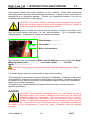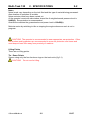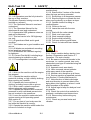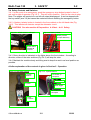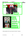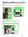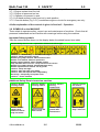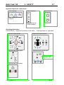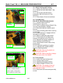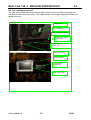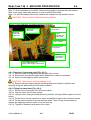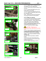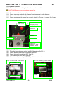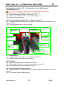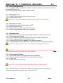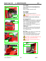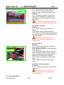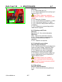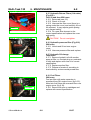
1
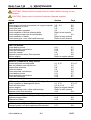
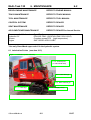
Multi-Task 120
SafeTrak
Operators’ Manual
Multi-Task 120
SECTION:
CONTENTS
1
1. Introduction and Purpose
2. Technical Specifications, Dimensions and Noise Level
3. Safety and Symbols
3.1
3.2
3.3
3.4
3.5
3.6
3.7
3.8
Ensure!
Never!
Always!
Safety controls and switches
Tracking Levers
Engine Stop switch
Control Cut outs
Symbols on the machine
4. Machine Preparation
4.1
4.2
4.3
4.4
4.5
Fuelling and parking
Fitting the tool
Removing the tool
Seat adjustment
Cab additional features
5. Operation
5.1
5.2
5.3
5.4
5.5
5.6
5.7
5.8
5.9
5.10
5.11
5.12
5.13
5.14
Pre-work checks
Starting machine
Moving machine
Autodrive controls
Starting the tool
Front Guard adjustment
Tilt adjustment
Tool Float
Frame adjustment
Tool crowd adjustment
Stopping the tool
Reversing the rotor
Operating Hints
On completion of work
©GreenMech Ltd
-1-
06/07
Multi-Task 120
CONTENTS
2
6. Maintenance
For Engine, Tracks and IQAN system please refer to separate
manuals
6.1
6.2
6.3
6.4
6.5
6.6
6.7
6.8
6.9
6.10
6.11
6.12
6.13
6.14
6.15
6.16
6.17
6.18
6.19
6.20
Routine Maintenance schedule
Raising Cab
Engine Oil
Coolant
Hydraulic Oil
Fuel level
Coolers (Radiator)
Steam Cleaning
Air Cleaner
Electrical Connections
Battery
Bearings and pivots
Hydraulic connections
Mountings
Hydraulic Return Filters
Hydraulic Pressure Filter
Hydraulic Oil change
Fuel Filters
Fuses
Fault finding chart
7. Storage
7.1
7.2
Storage
Removal from storage
8. Disposal
9. Appendix
9.1
9.2
9.3
9.4
Hydraulic Circuit
Electrical Circuits
Certificate of Conformity
Risk Assessment
©GreenMech Ltd
-2-
06/07
Multi-Task 120 1. INTRODUCTION AND PURPOSE
1-1
INTRODUCTION
This manual explains the proper operation of your machine. Read these instructions
thoroughly before operating and maintaining the machine. Failure to do so could result in
personal injury or equipment damage. Consult your GreenMech supplier if you do not
understand the instructions in this manual.
CAUTION! This symbol indicates important safety messages in this manual.
When you see this symbol, be alert to the possibility of injury to yourself or
others, and carefully read the message that follows.
We recommend that you keep this manual with the machine in the box, if provided. Note
here the serial number and quote it in any communications. This is important when
ordering spares. Remember to include all numbers and letters.
S/N plate on floor to left of seat
S/N plate
Serial Number...................
VIN number…………………
Write in the numbers!
This manual covers the GreenMech Multi-Task 120 Safetrak tool carrier fitted with Seppi
Mulching Head model…………………, new crane model………….and flail
model…………………………
CAUTION! Always refer to individual Instruction Manuals supplied with the engine
and tools.
If in doubt, always quote the serial number in any communications.
The information in this manual is correct at the time of publication. However, in the course
of development, changes to the machine specification are inevitable. Should you find any
information to vary from the machine in your possession please contact your GreenMech
dealer for up to date information.
The manual may contain standard and optional features and is not to be used as a
machine specification.
PURPOSE
CAUTION! This machine is designed solely as a tool carrier for use in
vegetation control and forestry operations and must only be fitted with
GreenMech approved attachments The machine should only be used by
trained operators who are familiar with the contents of this instruction
manual. It is potentially hazardous to fit or use any parts other than genuine
GreenMech parts. This machine is for Off Highways use only. GreenMech Ltd disclaims
all liability for the consequences of such use, which in addition voids the machine
warranty.
©GreenMech Ltd
1-1
06/07
Multi-Task 120
2. SPECIFICATIONS
Fig 2.1 Multi-task 120 Safetrak
2-1
Main features
Cab
Seat
Engine
covers
Frame
Tie-down
point
Linkage
Track leg
Mulcher
attachment
Track
TECHNICAL SPECIFICATION Multi-Task 120
Hydraulic drive Output
157 litres/min at 350 bar
Auxiliary hydraulic
2 double acting services 10 litres/min at 230 bar
1 double acting services 25 litres/min at 230 bar
Power unit
Fuel capacity
Hydraulic capacity
Length (without tool)
Length (with Seppi Mulcher)
Width over body
Track width
Track size
Height
Weight
Ground pressure
©GreenMech Ltd
90KW @ 2200rpm water cooled Deutz diesel
140Lt
190Lt
3600mm
4500mm
1500mm
1590mm-2490mm
250mm x 2145mm
2340mm - 2700mm
4880Kg
0.6kg/cm2
2-1
10/07
Multi-Task 120
2. SPECIFICATIONS
2-2
Noise
Noise levels vary depending on the tool fitted and the type of material being processed.
Also duration of operation is variable.
Noise emission tests have been carried out:
At the operator’s seat with cab window closed the A weighted sound pressure level is
84dB(A). Ear protection is recommended.
Outside the machine the guaranteed sound power level is 109dB(A)
Minimise noise by switching to idle or stopping the engine whenever work is not in
progress.
CAUTION! The operator is recommended to wear appropriate ear protection. Other
Site workers and bystanders are recommended to wear ear protection and visors and
must keep at least 20m away from proximity of machine.
Lifting Points
There are no lifting points.
Tie - Down Points
Secure using only the four tie-down rings on the track units (fig 2.1).
CAUTION!
©GreenMech Ltd
Do not use for lifting.
2-2
10/07
Multi-Task 120
3. SAFETY
3.1 ENSURE:
3.1.1 All Operators must be fully trained in
the use of their machine.
(Certificated Operator training courses are
available on request.)
3.1.2 The Operators Manual is read and
understood.
3.1.3 The Operators Manual for the
attachment is read and understood
3.1.4 Appropriate HSE guidance notes are
read and understood.
3.1.5 This tool carrier is for Off Highways
use only.
3.1.6 All guards are fitted and in good
condition.
3.1.7 Tool blades are in good condition and
secure.
3.1.8 All blades are maintained according
to tool suppliers instructions.
3.1.9 All fasteners are checked regularly
for tightness.
3.1.10 Correct First Aid Kit including large
wound dressing is available on site.
3.1.11 Fire extinguisher is available on site.
3.2 NEVER:
3.2.1 Work on the machine until the engine
has stopped.
3.2.2 Operate the machine without
protective clothing, or high visibility clothing
when working on roadside.
3.2.3 Operate with loose articles of
clothing, including loose cuffs on gloves.
3.2.4 Work under a raised component
without adequate safety support.
3.2.5 Operate the machine with untrained
personnel or with individuals present who
are not involved in the operations.
3.2.6 Leave the machine unattended with
engine running at full operating speed.
(See section 4)
3.2.7 Put any part of your body near the
tool while the machine is running.
3.2.8 Operate the machine whilst under the
influence of alcohol or drugs.
©GreenMech Ltd
3-1
3-1
3.2.9 Stand between the tracks and the
machine body.
3.2.10 Stand within 2 metres of the tracks
when the legs are being extended.
3.2.11 Extend legs in a dangerous manner.
3.2.12 Stop the engine or operate the tool
when moving directly up or down a slope.
3.2.13 Operate inside a building or
confined space.
3.2.14 Climb on the tool.
3.2.15 Leave the seat with the rotor
running.
3.2.16 Start with the cutter raised.
3.2.17 Work over loose rocks.
3.2.18 Work towards buildings.
3.2.19 Smoke whilst refuelling.
3.2.20 Fell trees without guard frame.
3.2.21 Check for leaks with bare hands.
3.3 ALWAYS:
3.3.1 Check machine before starting (see
Section 4 Preparation and Section 5.1
Operation: Pre-work checks).
3.3.2 Be aware of potential hazards in the
work area, i.e. uneven ground, tree roots,
obstructions and type of materials being fed
into the machine.
3.2.3 Approach work area slowly.
3.3.4 Have a second trained operator
within easy reach of the machine.
3.3.5 Maintain strict discipline at all times.
3.3.6 Service machine at specified periods.
(see Section 6: Routine Maintenance).
3.3.7 Note direction of debris discharge
and wind direction to prevent debris from
being blown into highway or where it could
affect members of the public.
3.3.8 Adjust legs to keep the body as level
as possible.
3.3.9 Check the route to the worksite for
gradients, undulations and obstructions.
3.3.10 Remove key before doing any
maintenance.
3.3.11 Check any unusual noise and
vibration.
05/08
Multi-Task 120
3. SAFETY
3-2
3.4 Safety Controls and Switches
3.4.1 In the event of an emergency, push the emergency stop button located in front of
cab roof to right of operator (Fig 3.4.1). This will lock in position. Wait for the rotor to stop.
Note: The engine will continue to run with all output disengaged. It can be stopped with
the key switch (see 3.6) but cannot be restarted without resetting the emergency button.
3.4.2 A battery isolator button is located in the fuse cabinet on the left hand side (Fig
3.4.2). This isolates all electrics except the alternator circuit.
CAUTION! See also section 4 Preparation: 4.4 Seat – 4.4.1 Safety
Fig 3.4.1 STOP Switch in cab roof
Fig 3.4.2 Battery isolator
Battery isolator
(except alternator)
STOP switch
isolates all
controls
3.4.3 Rotor direction is indicated on the lights above the front window. According to
direction, either of the rotor switches (Fig 3.4.3) will stop the rotor.
3.4.4 Maintain the machine body and tilting seat to keep the seat in as level position as
possible.
A fuller explanation of the controls is given in Section 5 - Operation
Fig 3.4.3 Left Hand Controls
Fig 3.4.4 Joystick Buttons
Joystick
Buttons
M1-Guard up
M2-spare
Tool Float
Joystick
Mode toggle
M1-Guard down
M2-spare
Rotor
Controls
©GreenMech Ltd
3-2
05/08
Multi-Task 120
3. SAFETY
3-3
Fig 3.4.5 Left Hand Joystick Movements - Mulcher head control
M1 Tool down
M2-Frame down
M1-Crowd out
M2-Tilt left
M1-Crowd in
M2-Tilt Right
M1-Tool Up
M2-Frame Up
Fig 3.4.6 LH Control switches
LH Track: Out - In
RH Track: In - Out
Seat Levelling
Left – Tilt - Right
Tool float pressure adjust
Clockwise - Increase
Track ‘Cruise control’
Toggle On - Off
Rotor: Reverse - STOP
Rotor: Forward - STOP
A fuller explanation of the controls is given in Section 5 - Operation
©GreenMech Ltd
3-3
05/08
Multi-Task 120
3. SAFETY
3-4
3.5 Tracking Levers (Fig 3.5.1 and Fig 3.5.2)
3.5.1 Lever controls operate the drives to the tracks. Push for forward motion. Pull for
reverse motion.
CAUTION! Machine can pitch forward and backwards when controls are operated.
Use firm control movements and familiarize before attempting rough terrain.
Fig 3.5.1 RH Track controls
Fig 3.5.2 Track levers
LH – Forward - RH
Track Levers
Fast - Slow
Cut-outs Override
(emergency only)
LH – Reverse - RH
Track Trim
Left - Right
Engine Key
3.6 Engine stop switch
3.6.1 To stop the engine, turn the start key anticlockwise (fig 3.6).
CAUTION! Do not restart engine until hazard has been removed.
Fig 3.6.1 Engine Key
Glow Plug
Alternator
Engine Key
Clockwise – Start
Anticlock - STOP
3.7 Control cut-outs
©GreenMech Ltd
3-4
05/08
Multi-Task 120
3. SAFETY
3-5
Cut-outs are installed to stop and prevent restarting due to specific events.
3.7.1 Engine coolant level too low.
3.7.2 Engine oil pressure too low.
3.7.3 Operator not present in seat.
3.7.4 Left hand armrest control pod not in work position.
3.7.5 Override button (Fig 3.5.1) immobilizes engine cut-outs for emergency use only.
A fuller explanation of the controls is given in Section 5 - Operation
3.8 SYMBOLS on the MACHINE
These relate to operator safety, correct use and maintenance of machine. Check that all
personnel understand and are familiar with meanings before using the machine.
Important Safety symbols
Take the correct action shown on the display below the stated hazard (see table)
General Safety decal in cab - explanation follows from left to right
Caution! / Remove key / Do NOT start engine
Caution! - Read instruction manual
Beware flying object hazard - Wear helmet & visor
Beware noise hazard - Wear ear protectors
Beware trapping hazard - Wear suitable clothes
Keep machine level-incorrect – Keep machine level-correct
Beware flying object hazard - Keep bystanders away
Beware exposed drives hazard - Fit all guards
Caution! - Keep nuts tight
Caution! - Max safe side slope 35deg
Caution! - Max safe up and down slope 25deg
Electricity! – Keep away from power lines
Caution! – Fasten seat belt
Additional Safety Decals located on machine
Caution! Beware
crushing hazard
Caution! Beware
crushing hazard
Action: Do NOT
stand in area
between machine
body and tracks
Action: Prop cab
when raised
©GreenMech Ltd
3-5
Caution! Beware
moving
components
Caution! Beware
hot surface
Action: replace
guards after
maintenance
Action: Keep
away - until cool
05/08
Multi-Task 120
3. SAFETY
3-6
Important Operating Checks Notice
Before use carry out daily the stated checks in the order shown (see table)
Daily Checks
Every 8 Hours –Daily checks
1. Check machine is level
2 Stop engine
3. Check coolant level
4. Check engine oil level
5. Check hydraulic oil level
6. Check all guards are in place
7. Start engine
Other Information
Noise level
Noise level in Cab
Ear defenders must
be worn outside cab
Ear defenders
recommended
Maintenance Information
Radiator cleaning
Grease point
40 hours / weekly
Hydraulic Filler
8 Hours
Check
radiator
screen
©GreenMech Ltd
40 Hours
Blow out
radiator
core
3-6
05/08
Multi-Task 120
3. SAFETY
3-7
Implement Hydraulic connections
Ram couplings
Motor Couplings
Rotor Direction
Note: Always use correct
locations
Note: Always use
correct locations
Operating Information
Control Decals Implement operation on left hand
Tracking motion on right hand
Left hand Joystick decal
Right hand Joysticks Decal
Left hand upper switch decal
Right hand upper switch decal
Cut-outs Override
(emergency only)
Left hand lower switch decal
©GreenMech Ltd
3-7
05/08
Multi-Task 120 4. MACHINE PREPARATION
4-1
4.1 Initial Fuelling and Parking
4.1.1 Ensure the machine is level.
4.1.2 Fill the fuel tank with diesel. See
section 6.
4.1.3 Top up the hydraulic tank if
necessary, with the correct oil. See
Section 6.
4.1.4 Clean faces of hose connections.
Fig 4.2.1 Tool hitch plate prepared
Teeth
4.2 Tool Mounting
(See 4.6 for boom flail attachment)
4.2.1 Connect catch hoses at
connections II. (fig 4.2.3)
4.2.2 Use LH joystick buttons Mode 2 (fig
3.4.4) to raise hydraulic catches.
4.2.3 Drive the machine carefully up to
the tool.
4.2.4 Hook mounting plate teeth under lip
on tool plate.
4.2.5 Lower catches to engage catches
into slots on tool plate.
4.2.6 Remove and park catch hoses.
4.2.7 Fit the motor (if not fitted) and
connect all hydraulic hoses (fig 4.2.3).
4.2.8 Operate the linkage controls to
check functions and lift the tool.
4.2.9 Check hoses remain clear of any
pinch points.
4.2.10 Check all guarding is in place.
4.2.11 Operate rotor control at Slow
speed to check operation.
Catches
underneath
Fig 4.2.2 Tool hitch plate engaged
Catches
engaged
CAUTION! Ensure all guards are
fitted correctly before use.
Fig 4.2.3 Hose connections
CAUTION! Before travelling, always
check the tool is free from debris.
Motor hose
connections
4.3 Tool removal
4.3.1 Lower tool onto level ground.
4.3.2 Connect catch hoses.
4.3.3 Carefully disengage catches.
4.3.4 Adjust linkage to release tool.
Ram hose
connections
CAUTION! The weight of the tool
may cause it to unhook suddenly and
pitch forward or back.
4.3.5 Disconnect all hoses and park tidily
on tool.
Ram hose connection pairs for
Mulcher - viewed as shown:
Frame : Spare : Front guard
Use II (spare) for catch hoses
©GreenMech Ltd
4-1
08/08
Multi-Task 120 4. MACHINE PREPARATION
4-2
4.4 Seat Adjustment
Fig 4.4 Seat Adjustment Controls (LH joystick pod not shown)
Armrest
adjuster
Backrest
adjuster
Absorber
Hard/Soft
Weight/Height
adjuster
Fore/aft isolator
(if fitted)
Fore/Aft
adjuster
4.4.1 Seat Safety
CAUTION! To prevent back damage, adjust to driver’s weight before use and before
every change of driver. See 4.4.2.1 below
CAUTION! Ensure no objects are within moving area of driver.
CAUTION! Check settings before use.
CAUTION! Do not adjust any settings while driving.
CAUTION! Use the seatbelt. Replace and check all mountings after an accident.
CAUTION! Do not place a load on the seat. Unexpected activation of presence
control may occur.
CAUTION! Do not adjust backrest with upholstery removed.
CAUTION! Do not attempt maintenance without specialist information from
manufacturer.
.
4.4.2 Seat Adjustments (Fig4.4)
4.4.2.1 Set weight with the machine and operator absolutely still, briefly pull weight/height
actuator. The shock absorber must be set to ‘Soft’ (4.4.2.6).
4.4.2.2 Set height by pressing weight/height actuator fully out or in. Do not operate for
more than 1 minute. The shock absorber must be set to ‘Soft’ (4.4.2.6).
4.4.2.3 Adjust backrest using locking lever. Ensure it is locked when set.
4.4.2.4 Set fore/aft position by lifting cross bar. Ensure it is locked when set.
4.4.2.5 Set armrest height using rollers under armrests.
4.4.2.6 Set absorber to suit terrain. Position 1 - soft Position 2 - hard
4.4.2.7 Set fore/aft isolator to suit conditions. position 1 - Off Position 2 - On
©GreenMech Ltd
4-2
08/08
Multi-Task 120 4. MACHINE PREPARATION
4-3
4.5 Cab - additional features
The cab is also fitted with external work lights (front and rear), windscreen wiper, air
conditioner with cabin light, radio, 12V output socket, and engine diagnostic button (for
dealer use only)
Fig 4.5.1 Cab Roof
Cabin Light
Air Conditioner
Work lights and wipers
Radio & 12V outlet
(not shown)
Engine diagnostic button
(dealer only)
Fig 4.5.2 Cab Front view
Emergency stop
Rotor Direction
Iqan Console
(dealer only)
Rear view screen
©GreenMech Ltd
4-3
08/08
Multi-Task 120 4. MACHINE PREPARATION
4-4
4.6 Flail Head on Crane Attachment
Note: To fit this attachment, the Multi-Task mounting plate is removed and the crane is
fitted in two parts, base plate and boom (with or without flail fitted).
Note: LH and RH always refer to the machine as viewed from the operator’s seat.
CAUTION! The use of an overhead crane is essential.
Fig 4.6.1 Front of Machine. Pin positions and hose connections
Stabilizer hose
connections
Steel Pipes
(Remove)
Mounting
Plate pins
(Remove)
Upper
Clevises for
base plate
Cap 2 outlets
Flail motor hose
connections
Lower
Clevises for
base plate
Cover Plate (Remove)
Boom valve supply connections
4.6.1 Removal of mounting plate (Fig. 4.6.1).
4.6.1.1 Rest the plate on the ground and support with a crane.
4.6.1.2 Disconnect all hydraulic pipes where attached to machine mainframe
4.6.1.4 Remove steel pipes to motor connections
CAUTION! Take care to minimise spillage of oil.
4.6.1.5 Remove all pins supporting the mounting plate and hydraulic cylinders and
carefully swing the plate away from the base machine.
4.6.2 Fitting the base plate (Fig. 4.6.1).
4.6.2.1 Remove the cover plate over RH hose outlets.
4.6.2.2 Cap the lower pair of hose outlets.
4.6.2.3 Using a crane, swing the base plate into position, leaving sufficient space to fit the
hoses.
4.6.2.4 Fit the hoses for the crane boom valve and stabilizer legs to the outlets as shown.
4.6.2.5 Fit the pins as shown to secure the base plate. Note: It may be necessary to
release the upper arm bolts in order to line the pins up.
4.6.2.6 Tighten all fasteners and remove the crane.
©GreenMech Ltd
4-4
08/08
Multi-Task 120 4. MACHINE PREPARATION
4-5
4.6.3 Fitting the boom with flail
4.6.3.1 Using a crane, swing the boom
into position onto the base plate.
4.6.3.2 Secure with 8 bolts as shown (Fig
4.6.3.1).
4.6.3.3 Connect the feed hoses to the
boom valve (if not fitted).
4.6.3.4 Fit the front guard (Fig 4.6.3.2).
4.6.3.5 Tighten all fasteners and remove
the overhead crane.
Note: Temporary removal of the boom
only may be carried out as required.
Fig 4.6.3.1 Boom to base plate bolts
Base plate bolts (8)
4.6.4 Fitting the controls
In use the twin joystick bracket is located
on the centre of the seat, between the
legs of the operator. It has a park socket
to the right of the cab to enable the
operator to enter and leave the seat.
4.6.4.1 Place the twin joystick assembly
in the park socket (Fig 4.6.4.1).
4.6.4.2 Connect all electric cables.
Fig 4.6.3.2 Front guard & stabilizers
Stabilizer Leg
CAUTION! Read the tool
Instructions before operating for the first
time
4.6.4.3 Check that the closed loop pump
boost pressure stabilizes at 25 bar by
cranking the engine without starting. See
fig (4.6.4.2) for pressure point behind
engine. If low, top up hydraulic oil (See
Section 6.5)
4.6.4.4 Test all operations as 4.6.5
below.
4.6.4.5 Sit in the seat and place the
joystick assembly into the central work
position (Fig 4.6.4.3).
4.6.4.6 Practice operating controls.
Guard
Fig 4.6.4.1 Boom joystick mountings
Joystick
Park
Joystick
socket
Fig 4.6.4.3 Boom joystick - Working.
Fig 4.6.4.2 Boost Pressure Point
Joysticks
Work
Joystick
socket
Boost pressure point
(furthest from view)
©GreenMech Ltd
4-5
08/08
Multi-Task 120 4. MACHINE PREPARATION
4-6
4.6.5 Operating functions.
Multi-Task Left Hand joystick is used for stabilizer legs only (Fig 4.6.6)
Fig 4.6.6 Left Hand Joystick Dual Mode Movements and Buttons - Stabilizer leg control
M1-III Spare
M2-II spare
M1 Spare
M2- I Spare
Spare
M1-LH leg OUT
M2-RH leg IN
M1-LH leg IN
M2-RH leg OUT
Joystick Mode
Toggle M1 – M2
M1-III Spare
M2-II spare
M1-Spare
M2-I Spare
Multi-Task LH switches are used for flail rotor controls as marked in Fig 5.3.3 Section 5
Boom joysticks. See Boom and Flail head Instruction Manuals for joystick operations
CAUTION! Read the tool Instructions before operating for the first time
©GreenMech Ltd
4-6
08/08
Multi-Task 120 5. OPERATION - MULCHING
5-1
5.1 Pre-Work Checks:
5.1.1 Check work area for foreign bodies, loose rocks, metal etc.
CAUTION! Sparks from the tool can cause fire.
5.1.2
5.1.3
5.1.4
5.1.5
Check no unauthorised people present.
Check other site workers are aware of machine and at a safe distance.
Check seat settings (see 4.4)
Check remote service hoses are correctly fitted. I = Frame, II = spare, III = Guard.
Fig 5.2.1 Right Hand - Engine Start Controls
Tracks
Slow - Fast
Cut-out Override
(Emergency only!)
Track Trim
Glow Plug
Alternator
Engine Key
Clockwise – Start
Anticlock - STOP
5.2 Starting Machine:
5.2.1 Put speed control toggle switch into SLOW position (fig 5.2.1)
5.2.2 Check all other personnel are clear of machine.
5.2.3 Check that rotor is switched OFF (Fig 5.3.1)
5.2.4 Turn start key to PRE-HEAT position.
5.2.5 After 5 seconds, turn key to START position to start engine.
Fig 5.3.1 Right Hand - Track levers
Fig 5.3.2 Reversing - CCTV Screen
LH – Forwards - RH
Rotor direction
Screen
LH – Reverse - RH
©GreenMech Ltd
5-1
05/08
Multi-Task 120 5. OPERATION - MULCHING
5-2
5.3 Moving the Machine
CAUTION! Before moving machine, check for obstructions directly behind.
5.3.1 Check that the tool is lifted clear of the ground.
5.3.2 Push both levers forwards together to start forward movement (Fig 5.3.1).
5.3.3 Check and use the CCTV screen for reversing (Fig 5.3.2).
5.3.4 Extend legs as required, keeping body level. (fig 5.3.3)
5.3.5 Switch speed SLOW to FAST to increase speed (Fig 5.2.1).
5.3.6 Push left or right lever to steer. See also 5.3.9.
5.3.7 At work site adjust legs to level the body as much as possible.
5.3.8 Level Seat as much as possible (Fig 5.3.1).
5.3.9 Set Track Trim knob to bias steering to left or right as required (Fig 5.2.1).
Note: When extending or retracting legs it is advisable to track the machine.
Fig 5.3.3 Left Hand - Control switches
LH Track: Extend - Retract
RH Track: Retract - Extend
Seat Levelling
Left – Tilt - Right
Tool float pressure adjust
Clockwise - Increase
Track ‘Cruise control’
Toggle On - Off
Rotor: Reverse - STOP
Rotor: Forward - STOP
CAUTION! When extending legs, do not force track against solid objects. This may
dislodge track.
CAUTION! Avoid static turns on hard surfaces. This will rapidly wear the tracks
CAUTION! Do not drive directly up slopes exceeding 25 degrees. Slopes up to 35
degrees may be traversed with care.
5.4 Autodrive controls
5.4.1 The ‘cruise control’ toggle (Fig 5.3.3) may be used to lock a set speed.
5.4.2 The machine may then be steered using the track trim bias knob (Fig 5.2.1)
5.4.3 The track trim bias may be used to maintain direction across a slope.
Note. The set speed is reduced to a stop when the mulching tool becomes
overloaded.
CAUTION! Reset track trim bias to straight position prior to driving on roadways.
©GreenMech Ltd
5-2
05/08
Multi-Task 120 5. OPERATION - MULCHING
5-3
The following Instructions 5.5 – 5.13 apply to use of the Mulching tool
5.5 Starting the Tool
CAUTION! Read the tool Instructions before operating for the first time
5.5.1 Switch rotor to FORWARD to start the rotor (Fig 5.2.1).
5.5.2 Note rotor direction is correct for work (Fig 5.3.2).
5.5.3 Switch from SLOW to FAST Increase speed (Fig 5.2.1).
5.5.4 Approach the work slowly.
5.6 Front Guard adjustment (Fig 5.6.1). Remote Service III
5.6.1 Toggle joystick mode button to select Mode 1 - guard movement obtained on LH
joystick buttons.
5.6.2 Use Left Hand buttons to set front guard.
Fig 5.6.1 Left Hand Joystick Dual Mode Movements and Buttons - Mulcher head control
M1-III Guard up
M2-II spare
M1 Tool down
M2- I Frame down
Tool Float
M1-Crowd out
M2-Tilt left
M1-Crowd in
M2-Tilt Right
Joystick Mode
Toggle M1 – M2
M1-III Guard
down
M2-II spare
M1-Tool Up
M2-I Frame Up
5.7 Tilt adjustment
5.7.1 Toggle joystick mode button once to Mode 2 (Fig 5.6.1)
5.7.2 Push joystick to left or right to adjust tool tilt.
5.8 Tool Float
5.8.1 Press tool float button once to allow tool to float
5.8.2 Press again to restore lift control or pull joystick to operate lift
5.8.3 Adjust float pressure with rotary knob (Fig 5.3.3)
5.9 Frame adjustment Remote Service I
5.9.1 Toggle joystick mode button to Mode 2 to switch joystick movement from tool lift to
frame lift.
5.9.2 Pull or push joystick to adjust frame.
©GreenMech Ltd
5-3
05/08
Multi-Task 120 5. OPERATION - MULCHING
5-4
5.10 Tool Crowd adjustment
5.10.1 Toggle joystick mode button to Mode 1 to switch joystick movement from tool tilt to
tool plate tilt fore and aft.
5.10.2 Move joystick to left or right to adjust crowd.
5.11 Stopping the Tool
5.11.1 Press Forward switch down to stop the motor.
5.11.2 Wait for tool to stop.
CAUTION! The rotor will take several minutes to stop due to its inertia.
5.12 Reversing the rotor.
5.12.1 Stop the rotor with Forward switch to OFF.
5.12.2 Wait for rotor to stop.
5.12.3 Switch Reverse switch from OFF to Reverse
5.12.4 Check guard positions and close if necessary.
5.13 Operating Hints
5.13.1 Always set the pitch of the tool and guard settings to suit the type of work.
5.13.2 Do not approach too fast.
5.13.3 Use in float mode where possible to allow head to align with ground.
5.13.4 Close front guard and lift tool before turning.
5.13.5 Select SLOW to reduce speeds to idle when not working.
5.13.6 Use Autodrive controls (Section 5.4) when possible to save operator fatigue
CAUTION! Always read the Instruction Manual(s) supplied with the tool.
CAUTION! Keep working area around the machine clear at all times and check only
authorised personnel are present and in safe position.
5.14 On Completion Of Work
5.14.1 Check that engine has stopped and rotor is stationary.
5.14.2 Remove surplus material from rotor and machine surfaces.
5.14.3 Lower tool
5.14.4 Park machine and lock cab.
CAUTION! Do not leave machine parked directly up or down slope.
Note: Remote Service II is spare and used only to operate hydraulic catches for
implement plate when hoses are fitted. See Section 4.2
©GreenMech Ltd
5-4
05/08
Multi-Task 120
6. MAINTENANCE
6-1
ROUTINE MAINTENANCE SCHEDULE
CAUTION! Always remove key and check for rotation before carrying out any
maintenance.
CAUTION! Always refer to individual Instruction Manuals supplied.
Action
DAILY
Check engine oil level and coolant (ref: engine manual)
Check hydraulic oil level
Check fuel level
Check fuel water separator
Check condition of all tool retaining bolts
Clean radiator screen and around radiator
Check condition of tracks
Check track gear, nuts, rollers and bearings
6.3 – 6.4
6-5
6.5
6-5
6.6
6-5
6.6
6-5
Refer to tool manual
6.7
6-6
Refer to track manual
Refer to track manual
FIRST 50 HOURS
Check battery levels
Check hydraulic connections
Check all mountings
Check air cleaner
Replace hydraulic return filter elements
Service engine
6.11
6-7
6.13
6-7
6.14
6-7
6.9
6-6
6.15
6-8
Refer to engine manual
WEEKLY in addition to Daily actions
Grease all pivots and slide pads
Blow out radiator core with air line
Steam clean machine
Clean air cleaner
Check electrical connections
Check battery levels
Check hydraulic connections
Check all mountings
6.1, 6.12
6.7
6.8
6.9
6.10
6.11
6.13
6.14
250 hours in addition to Daily and Weekly actions
Check condition of bearings and pivots
Check all fluid levels
Service engine
Check track gear units, rollers and bearings
Replace return filter elements
6.1, 6.12
6-3, 6-7
6.3, 6.4, 6.6
6-6
Refer to engine manual
Refer to track manual
6.15
6-8
500 hours in addition to Daily and Weekly actions
Replace pressure filter
Replace fuel filters
6.16
6.18
6-8
6-8
1000 hours in addition to 250 hour actions
Change hydraulic oil when replacing filter element
6.17
6-8
©GreenMech Ltd
6-1
Section
Page
6-3, 6-7
6-6
6-6
6-6
6-6
6-7
6-7
6-7
10/07
Multi-Task 120
6. MAINTENANCE
6-2
DIESEL ENGINE MAINTENANCE
REFER TO ENGINE MANUAL
TRACK MAINTENANCE
REFER TO TRACK MANUAL
TOOL MAINTENANCE
REFER TO TOOL MANUAL
CONTROL SYSTEM
REFER TO DEALER
SEAT MAINTENANCE
REFER TO DEALER
AIR CONDITIONER MAINTENANCE
REFER TO DEALER for Annual Service
Recommended lubricants
Hydraulic Oil*
Grease
Engine
Specification
EQUIUIS ZS46 (ISO6743/4 DIN 51524 HVLP)
Complex grease EP2 (high temperature)
SAE 10W-40 ACEA A3/B3
*Use only GreenMech approved oil in the hydraulic system.
6.1 Lubrication Points (see also 6.13)
Fig 6.1.1 Lubrication points summary
6.1.5 Seat tilt pivot
(in cab behind seat)
6.1.3 Link rams (4)
6.1.4 Hitch catches (2)
6.1.1 Track legs
©GreenMech Ltd
6.1.2 Linkage (1 arm)
6-2
10/07
Multi-Task 120
6. MAINTENANCE
6-3
Fig 6.1.2 Lubrication points detail
6.1.2
6.1.5
(Behind seat)
6.1.3
6.1.1
6.1.6
6.1.4
(behind)
Grease except where stated
6.1.1
Track legs each side
6.1.2
6.1.3
6.1.4
6.1.5
6.1.6
6.1.7
Clean and smear with grease. Operate
full stroke to spread grease.
Nipple each end of arm
Nipple each end of ram
Nipple behind hitch plate
Nipple behind seat
Nipple behind hitch plate
Link arm
Link rams (two)
Hitch plate catches
Seat pivot
Tilt ram
©GreenMech Ltd
6-3
10/07
Multi-Task 120
6. MAINTENANCE
6-4
6.2 Raising Cab
The following components are accessed
for maintenance by tilting the cab
forwards on its mountings. Battery,
Hydraulic return filter, Control valve…
6.2.1 Check that the tool is lowered to
ground.
6.2.2 Remove any loose equipment from
cab.
6.2.3 Fit cab pivot pins to front tilt hinges.
Pins are stored in hand pump enclosure.
(fig.6.2.1)
6.2 4 Remove mounting bolt covers from
four corners. (fig 6.2.2 & 6.2.3)
6.2.5 Remove 8 M12 mounting bolts.
6.2.6 Place handle into hand pump on
left of machine.
6.2.7 Pump until cab is fully raised.
6.2.8 Locate prop to secure (Fig 6.2.4).
6.2.9 To lower, turn knob to gently
release pressure. Check cables and
hoses.
6.2.10 Refit bolts and tighten to secure
cab in operating position.
6.2.11 Replace covers.
6.2.12 Remove pivot pins and stow with
hand pump.
Fig. 6.2.1 Cab lift pump
Tilt pivot pin
Hand pump
Fig. 6.2.2 Cab Front Mounting Bolts
under covers
Cab Mounting
Bolts under
cover in each
corner of cab
CAUTION! Ensure raised cab is
mechanically propped before carrying out
maintenance.
Fig. 6.2.3 Cab Bolts behind seat
CAUTION! Check hoses and cables
are not trapped as cab is lowered.
Fig. 6.2.4 Cab mechanical prop
Prop
Cab Bolts
©GreenMech Ltd
6-4
10/07
Multi-Task 120
6. MAINTENANCE
6-5
Check daily
6.3.1 Release locks and swing back left
hand engine cover to reveal dipstick and
filler (fig 6.2).
Refer to engine manual to refill.
Fig. 6.3 Engine dipstick
Filler
6.4 Coolant
Check daily
6.4.1 Refill as required (fig 6.4).
CAUTION! Do not remove cap when
engine is hot.
Note: Before winter check antifreeze.
Dipstick
6.5 Hydraulic Oil
Check daily at level indicator on right hand
side. Correct level is half way up indicator.
6.5.1 To refill unlock and lift rear cooler
cover to access filler (Fig 6.5).
6.5.2 If below mark, check for leaks and
refill to correct level.
1000 hours
6.5.3 Remove drain plug, Drain tank and
refill with clean oil of correct specification.
6.5.4 Replace filter.
Fig.6.4 Coolant filler
Filler
6.6 Fuel
6.6.1 Check daily before work and fill with
diesel as required. (Fig 6.6.1)
6.6.2 Check water separator (RH engine
cover) and drain if required. (Fig 6.6.2)
Fig 6.5 Hydraulic Filler and level
Level
CAUTION! Use clean diesel fuel only.
If in doubt, use a funnel with a filter.
CAUTION! Do not use any form of
synthetic fuel.
Filler
Fig 6.6.2 Fuel water separator
Fig 6.6.1 Fuel
Water separator
Fuel Fillers
6.3 Engine Oil
©GreenMech Ltd
6-5
10/07
Multi-Task 120
6. MAINTENANCE
6-6
Daily
6.7.1 Unlock and raise rear cooler cover.
6.7.2 Remove clips and lift out each
radiator screen, clean and replace (fig 6.7).
50 hours
6.7.3 In addition to above, remove rear
engine cover and blow out radiator core
from below with suitable airline and clear
from above.
Fig 6.7 Cooler Screens (2)
Screens
CAUTION! A build up of debris risks
overheating of the engine and a risk of fire.
6.8 Steam Cleaning
50 hours
6.8.1 Check all covers are fitted and
closed.
6.8.2 Steam clean machine surfaces.
6.8.3 Clean exposed electrical components
with a damp rag, spray with WD40 and then
wipe with dry rag.
CAUTION! Do not steam clean
directly on to electrical components, e.g.
control boxes.
6.9 Air Cleaner
50 hours
6.9.1 Unlock and hinge back right hand
engine cover to access.
6.9.2 Release clips and remove aircleaner
cover (fig 6.10).
6.9.3 Release wingnut, slide out element
and either blow out with air-line or gently
tap on smooth ground to release debris. If
badly contaminated replace element.
6.9.4 Replace and tighten wingnut fingertight.
6.9.5 Replace cover and close engine
cover.
Fig 6.9 Air Cleaner
Air Cleaner
6.10 Electrical connections
50 Hours
6.10.1 Check all wiring loom connections
are secure.
CAUTION! Poor connections will
affect engine security cut-outs and may
prevent starting.
6.7 Coolers (Radiator)
©GreenMech Ltd
6-6
10/07
Multi-Task 120
6. MAINTENANCE
6-7
6.11 Battery (under cab)
50 hours
6.11.1 Raise cab (see 6.2)
6.11.2 Check electrolyte level and top up if
required (fig 6.12.1)
Fig 6.11 Battery (under cab)
Cut-out
CAUTION! Gases are explosive.
Electrolyte is corrosive. Avoid sparks and
spillage.
6.11.3 Removal of battery
6.11.3.1 First disconnect negative (-) cable.
6.11.3.2 Disconnect positive (+) cable.
6.11.3.3 Remove clamps and carefully lift
out battery.
6.11.3.4 Replace by connecting positive
cable before negative.
Battery
6.12 Bearings and Pivots
50 hours
See section 6.1 for routine lubrication.
250 hours
Note. refer to tool instruction manual.
6.12.1 Check rotating components for
excessive movement and noise in
operation.
6.12.2 Replace as required.
6.13 Hydraulic connections
50 hours then 250 hours
6.13.1 With the aid of the circuit diagram to
follow the hose routings, check all hoses
and connections for leaks and damage.
6.13.2 Replace any worn or damaged
hoses with the correct type and length.
6.13.3 Before removal, check routing and
ensure replacement hose is fitted free of
strains, twists or kinks.
CAUTION! Ensure any residual
pressure is released before dismantling.
CAUTION! Ensure hoses are refitted
free of twists and kinks.
6.14 Mountings
50 hours then 250 hours
6.14.1 Check that all mounting bolts are
tight.
©GreenMech Ltd
6-7
10/07
Multi-Task 120
6. MAINTENANCE
6-8
Fig 6.15. Hydraulic Return filters
6.15 Hydraulic Return Filters (Cab raise)
(Fig 6.18.)
First 50 and then 250 hours
6.15.1 Raise cab (see 6.2)
6.15.2 Check oil is cool.
6.15.3 Unscrew the filter cover (there is a
spring under the cover) and carefully lift out
the element. It may require gentle prising
out, discard safely).
6.15.4 Fit a new filter element to the
correct specification and replace the cover
and spring.
Filters
CAUTION! Do not overtighten.
Fig 6.16. Hydraulic pressure filter
6.16 Hydraulic pressure filter (Fig 6.16)
500 hours
6.16.1 Unlock and lift out rear engine
cover.
6.16.2 Unscrew pressure filter and replace.
6.17 Hydraulic Oil change
1000 hours
6.17.1 Remove hydraulic oil with suction
pump at filler, or via drain plug on underside
of tank and replace with new oil of correct
specification.
6.17.2 Replace suction filter.
6.17.3 Dispose of waste oil according to
local authority environmental procedures.
PressureFilter
6.18 Fuel Filters
500 hours
Fuel pre-filter with water separator is
accessed from RH engine cover (fig 6.6.2).
Main twin fuel filters are accessed from rear
engine cover (fig 6.18).
6.18.1 Remove all spin on cartridges and
replace with correct specification.
Fig 6.18 Fuel filters
Fuel Filters
©GreenMech Ltd
6-8
10/07
Multi-Task 120
6. MAINTENANCE
6-9
Fig 6.19. Fuse cabinet
Fuse - Master
6.19 Fuses
Fuses are accessed behind door on left hand
side (behind cab), except for engine preheat on
back of engine.
Fuse - Alternator
Fuses - Electronics
Fuses – radio equip.
Fuses - ancillaries
Fuse table
Fuse function
Engine preheat
Master to busbar
Alternator charge
Location
Back of engine
Top of cabinet
Side of cabinet
Value
125A
200A
200A
Colour
Ignition/start switch
Seat ram
Base of cabinet
Base of cabinet
20A
30A
N (Thick)
RW
Front lights
Base of cabinet
25A
RY
Rear lights
Base of cabinet
15A
RU
Wipers + Modem
Power Socket + Radio
MDM display / LH Joystick
Power XT2A0 electronics (part)
Power XP2A1 electronics (part)
Power XP2A0 electronics (part)
Base of cabinet
Bas of cabinet
Base of cabinet
Base of cabinet
Base of cabinet
Base of cabinet
20A
15A
5A
20A
20A
20A
RB
NR
RY
RO
RW
R
Power ECU Via Main Relay
Heater Matrix Via eater Rely
Coolant Level Switch
A/C Compressor Via A/C Relay
Spare/Crane
Air Filter + ECU Via Emergency Stop Rely
for ECU
Base of cabinet
Base of cabinet
Base of cabinet
Base of cabinet
Base of cabinet
Base of Cabinet
25A
30A
5A
7.5A
40A
7.5A
R (Thick)
W (Thick)
GU
UG
NY
OW
(Thick)
(Thick)
(Thick)
©GreenMech Ltd
6-9
10/07
Multi-Task 120
6. MAINTENANCE
6-10
6.20 Fault finding
Fault
Engine will not start
Machine unsteady
Unusual noise(s)
Track legs do not extend
Tracks do not drive
©GreenMech Ltd
Check
Emergency stop
Operator presence
Left hand control pod
Battery isolator
Battery
Fuel
Oil pressure
Coolant level
Fuses
Action
Check and release
Check seated correctly
Check in work position
Check switched ON
Recharge
Fill tank
Check Oil level
Fill coolant
Check
Page
3-2
3-5
3-5
3-2
6-7
6-5
6-5
6-5
6-9
Track legs
Tool rotor and bearings
Hydraulics
Hydraulics
Set to correct position
Check and replace
Check operation
Check operation
5-1
6-7
6-13
6-13
6-10
10/07
Multi-Task 120
7. STORAGE
7-1
7.1
Storage
7.1.1
7.1.2
7.1.3
7.1.4
7.1.5
7.1.6
Remove tool
Thoroughly clean machine and note any replacement parts required.
Carry out 250 hour service if not already done. Refer to Section 6
Fit replacement parts when available.
Remove battery.
Refer to 6.11
Drain fuel
7.2
Removal from Storage
7.2.1 Charge battery and refit
7.2.4 Carry out machine preparation as necessary
©GreenMech Ltd
7-1
Refer to 6.11
Refer to Section 4
06/07
Multi-Task 120
8. DISPOSAL
8-1
When the machine is finally scrapped, the following items should be disposed of only at
authorised waste disposal facilities.
Engine oil. Hydraulic oil. Antifreeze. Battery. Tracks.
If in doubt, consult the Local Authority environmental department.
Major non-ferrous items such as hydraulic hoses may also be disposed of separately.
©GreenMech Ltd
8-1
06/07
Operating & Faulting Finding Parker’s Hydraulic System
and IQAN Control System
Operating The Machine
Two Operating Conditions
Mulching Mode – Normal default working mode for travelling with the machine and using it with a mulching
head or flail mower.
Chipping Mode – Engaged when selecting – latch spare functions.
In this mode the Main Hydrostatic Drive and Spare Up function are the only functions available.
Hydrostatic Drive for the chipper drive and the spare for the chipper feed function
The driver does not have to be seated in the cab to operate these functions in this mode.
Operating Safety – Default Mulching Mode
Switch in Seat
System is not functional if the operator is out of the seat, if the operator gets out of the seat all the machine
functions will stop.
Start Up
After start up all functions must be in their – de-activated position before the system becomes available.
Joystick Lever – Mode Select
The Joystick must be in the central position and no buttons activated on the lever before you can change the
Joystick working mode.
If the Float Function is latched it will remain latched when selecting between modes.
On/OFF Functions – Hold to Activate
Digital Outputs on Expansion Units – XP2-A0, XP2-A1 & XT2-A0 - Crowd, Rotate, Frame, Guard, Right Leg, Left
Leg & Spare
What Controls these Functions? – Operator Using - IQAN-LL Lever Axis, Buttons in Handle or Switches mounted in
the operator’s panel.
What Stops the Functions Operating? – Operator not in Seat, Wrong Mode Selected on the Lever
Proportional Functions
Current Output on Expansion Units – XT2-A0 - Lift/Lower Head
What Controls the Functions? – Operator Using - IQAN-LL Lever Axis
Operator Selecting Float Function
What Stops the Functions Operating? – Operator not in Seat.
Another Function Selected at Start Up.
Wrong Mode Selected on the Lever – For Lift/Lower Function Only
Machine in Chipping Mode – Lift/Lower
Operator releases the Lever.
Current Outputs on Expansion Units - XT2-A0 - Mulching Head Forward & Reverse
What Controls the Functions? – Latch Type Switches mounted on the Operators panel.
Page 2 of 20 Pages
What Stops the Functions Operating? – Operator not in Seat – Mulching Mode Only
Switch to activate the mulching in the opposite is latched – Both switches
must be in the de-activated position before selecting the mulching
function.
Note: – Mulching Head is an On/Off Function but requires a current output with 3 sec ramp time from zero to full
speed and the same for full to zero speed.
In Chipping Mode – The Mulching Head will operate without the need for the operator to be in the seat.
Current Outputs on Expansion Units – XP2-A0 Left & Right Tracks
What Controls the Functions?
Operator Using - IQAN-LSL Levers
What Latches these Functions?
Switch on Operators Panel
What Stops the Functions Operating?
Operator not in Seat!
A Function Selected during Start Up
Machine in Chipping Mode – Lift/Lower of Head & Tracks Only
Operator releases lever – Unlatched Condition Only
If the operator selects any or both levers in the opposite direction or
activate the latching switch again. – Latched Condition Only
What Controls Track Speed? -
Operator via IQAN-LSL Levers
Engine Speed Drops Below 1600 RPM – Reduces current to both tracks Tracks slow down
Mulching Pressure > 330 Bar – Reduces current to both tracks - Tracks
Slow Down
Second Speed Select – Selects a different motor displacement – High
Torque Low Speed or the opposite
Trim Potentiometer - mounted in operators panel trims steering of vehicle,
reduces current to one track - one track only slows down.
Other Current Output Functions
Current Outputs Configured as Digital Outputs – XP2-A0 & XP2-A1 - Float Select Solenoid, Float Rotate
Solenoid
Proportional Current Output – Float Control Solenoid
What Controls the Functions? –
Operator via - IQAN-LL Latched Button – Push On/Push Off
Float Rotate Solenoid - Operates Automatically 0.5secs. after Float
Functions reaches its required Float Pressure Level
Mulching Pressure> 340Bar – Float Pressure will increase to lift Mulching
Head
What Stops the Functions Operating? – Operator not in the Seat!
Wrong Mode Selected on the Lever
Machine in Chipping Mode – Lift/Lower of Head & Tracks Only
Engine Speed below 1200 RPM
Operator Presses Button to De-activate Float Function
Page 3 of 20 Pages
Current Outputs Configured as Digital Outputs – XP2-A1 Two Speed Select – Selects 2nd Displacement on
the Track Motors
What Controls the Functions? –
Operator via – Switch in Panel
Tracks have to be at < 20% of their set current for 1 sec – Tracks on
automatically ramp down over .5 sec to <20% and then increase to
selected speed over 0.5sec
What Stops the Functions Operating? – Operator not in Seat!
Machine in Chipping Mode
Current Outputs Configured as Digital Outputs – XP2-A1 Fan Dump Solenoid – When Energized the Hyd Oil
Cooler Fan is at a very low speed.
What Controls the Functions? –
Automatically Controlled by IQAN from Temperature Sensor in Hydraulic
Reservoir –
Oil Temp > 50OC Solenoid De-energised Cooling Fan Running At Max
Speed
Oil Temp < 40OC Solenoid Energised Fan Running at Minimum Speed
What Stops the Functions Operating? – Ignition Off
Current Outputs Configured as Digital Outputs – XP2-A0 Pump Load Solenoid – De-energise Solenoid to
bring the Variable Displacement Implement Pump on Load when any of the On/Off Cetop. Directional Valves are
Selected.
What Controls the Functions? –
Automatically Controlled by IQAN any time the one of the On/Off
Functions are selected by the operator.
Page 4 of 20 Pages
Initial Start Up of Machine or After Major Machine Overall
Before initial start up of the engine, fit a pressure gauge to the pump outlet and in the Load Sense Pressure hose to
the pump.
Note! The engine should not be started without first checking the following:1. All the pipes and hoses are connected correctly and the fitting are fully tightened.
2. All the electric connections are fitted and tightened.
3. Hydraulic Reservoir is filled to the recommended level and the pumps are primed. (See Pump Initial Start
Procedure)
4. The pre- Engine Start Up procedure has been completed (See Engine Instructions).
5. The Correct Application File is present in the IQAM-MDM Unit.
6. There are no IQAN. Communication or other faults reported – All the IQAN expansion modules should have a
constant green and flashing orange light.
Note! The majority of the IQAN – inputs and outputs can be checked using a laptop computer without
running the engine. (See the IQAN Check Procedure). To correct faults use the Fault Finding Procedure.
Checks After Starting Engine.
Main Implement Pump should be at Standby Pressure
Fan Drive on the Engine Cooling Radiator should be running.
The Mulching Head should not be turning.
Before running any functions:Check the Main Implement Pump Standby Pressure - Pressure at Pump Outlet should not be 25 + 2.5/- 0 bar.
Check the charge pressure at the Mulching Head Pump is to the correct level
Note! For details on how to set up the pumps see the manufactures instructions. Use the fault finding
procedures to correct any faults.
Use the Trouble Shooting Procedure to correct any faults.
Setting Up the System
Checking the Pump Pressures
The pump pressure setting should be set in accordance with the suppliers recommendations.
Checking the Valve Pressures
The three – Spool Proportional Directional Control Valve (L90LS) is supplied with the maximum pressure levels set
at the factory and should not be adjusted unless absolutely necessary.
To Check the Relief Valve Setting – The pump cut out pressure setting has to be set to approximately 20 bar above
the desired setting on the valve. The relief valve on the valve should then be set to the correct pressure level (see
circuit drawing) After the Relief Valve on the main valve is set the pump cut pressure should be reset so that it is 20
bar below the valve setting. These setting should be down by stalling out one of the lower flow on/off functions.
Page 5 of 20 Pages
The Relief Valves on the A & B ports of the Track spools cannot be adjusted these are pre-set and welded at the
supplier’s factory.
Check the Functionality
Safety Functions
All functions should stop when the operator leaves the seat. If the operator then returns to his seat it should not be
possible to re-activate a function by the action of the operator sitting down again. All switches/levers have to be
returned to their off position before any function can be re-activated.
On/Off Functions on Multi–Valve Manifold – Settings the Speed
Mulching Head – Function & Speed
Track Function & Speed
Boom Lift & Lower Function
Float Function
Float Rotate Function
Mulching Head - Anti-Stall Function
Fan Drive Speeds & Function
IQAN – Check Procedure
Connect a laptop to the IQAN-MDM Unit using the RS232 Cable – Parker Part No. 5030024.
Note! If the laptop does not have an RS232 Serial Connector a suitable USB to Serial Adaptor will be required
Boot up the computer and open the IQAN –Change Software before switching the Ignition On
Switch on the ignition, but do not start the engine, Check that the Computer Com Port is now on line (Bottom
right hand corner of the IQAN-Change Window) – If no communication is established check that the correct COM
port is selected. (Should be the same as for the Serial Port or USB adaptor) If not change this by going to the file
drop down box and selecting properties and the communication tab then select the correct Com Port.
Upload the Application File from the IQAN-MDM Unit by pressing the Get Application from IQAN system Icon on
the Menu Bar – Application should download and the five CANBUS IQAN modules should be seen in the System
Overview Tab. Check the application file is correct and is the latest issue.
If there is no Application File in the IQAN – MDM Unit, open the latest file in the IQAN-Change Software and
download this to the IQAN-MDM using the Send application to the IQAN-System Icon on the Toolbar.
Note! For more detail about these procedures see the IQAN-develop Manual.
Page 6 of 20 Pages
Having established communication between the laptop and the IQAN System the IQAN-Change Software can be
used to check all of the inputs from the levers, switches and sensors without the engine running only the ignition on
For details about how to do this see Measuring & Fault Finding Page 311 of the IQAN-Develop manual.
Page 7 of 20 Pages
Input Specifications
Channel
Voltage Inputs
Trim Float Switch (IQAN-LL)
A
Seat Switch (IQAN-LL)
B
Track Right Primary (IQAN-XP2-A0)
A
Track Right Secondary (IQAN-XP2-A0)
B
Track Left Primary (IQAN-XP2-A0)
C
Track Left Secondary (IQAN-XP2-A0)
D
Mulch Pressure (IQAN-XP2-A1)
A
Fuel Filter (IQAN-XP2-A1)
B
2nd Speed Select (IQAN-XP2-A1)
C
Air Filter (IQAN-XP2-A1)
D
Hyd. Oil Filter (IQAN-XT2-A0)
B
Hyd. Oil Temperature (IQAN-XT2-A0)
C
Main Filter Indicator (IQAN-XT2-A0)
D
Transmission Filter Indicator (IQAN-XT2-A0)
E
Track Trim Potentiometer (IQAN-XT2-A0)
F
Fuel Sensor (IQAN-XT2-A0)
G
Track Latch Inputs (IQAN-XT2-A0)
H
Page 8 of 20 Pages
Max.
Min.
Input Specifications
Channel
Digital Inputs
Left Leg In (IQAN-LL)
A
Left Leg Out (IQAN-LL)
B
Right Leg In (IQAN-LL)
C
Right Leg Out (IQAN-LL)
D
Mulching Head FWD. (IQAN-LL)
E
Mulching Head REV. (IQAN-LL)
F
Guard/Spare Up (IQAN-LL)
G
Float Latch Switch(IQAN-LL)
H
Guard/Spare Down (IQAN-LL)
I
Mode Switch (IQAN-LL)
J
Directional Analogue
Channel
Crowd & Rotate (IQAN-LL)
X
Lift & Frame (IQAN-LL)
Y
Page 9 of 20 Pages
Max.
Min.
Max.
Min.
Output Specifications
Channel
Current Outputs
Left Track Valve (IQAN-XP2-A0)
(Operator must be in the Seat)
A1
Right Track Valve (IQAN-XP2-A0)
(Operator must be in the Seat)
B1
Pump Load Solenoid (IQAN-XP2-A0)
(Activated on Start Up )
C1
Configured as Digital Output
Float Select Solenoid (IQAN-XP2-A0)
Configured as Digital Output
Second Speed Solenoid (IQAN-XP2-A1)
Activated during Boom Lift & Float Activation
(Operator must be in the Seat)
D1
(Operator must be in the Seat)
A1
(Operator must be in the Seat)
B1
(Operator must be in the Seat)
C1
Activated at Temp
D1
Mulching Head Solenoid (IQAN-XT2-A0)
(Operator must be in the Seat)
A1
Lift Up/Down Solenoid (IQAN-XT2-A0)
(Operator must be in the Seat)
B1
Configured as Digital Output
Float Rotate Solenoid (IQAN-XP2-A1)
Configured as Digital Output
Float Control Solenoid (IQAN-XP2-A1)
Configured as Digital Output
Fan Dump Solenoid (IQAN-XP2-A1)
Configured as Digital Output
Page 10 of 20 Pages
Max.
Min.
Digital Outputs
Channel
Max.
Min.
12 Volt
0 Volt
Frame Up Solenoid (IQAN-XP2-A0)
(Operator must be in the Seat)
A1
Frame Down Solenoid (IQAN-XP2-A0)
(Operator must be in the Seat)
B1
Guard Up Solenoid (IQAN-XP2-A0)
(Operator must be in the Seat)
C1
Guard Down Solenoid (IQAN-XP2-A0)
(Operator must be in the Seat)
D1
Crowd Fwd Solenoid (IQAN-XP2-A1)
(Operator must be in the Seat)
A1
Crowd Back Solenoid (IQAN-XP2-A1)
(Operator must be in the Seat)
B1
Head Rotate Left (IQAN-XP2-A1)
(Operator must be in the Seat)
C1
Head Rotate Right (IQAN-XP2-A1)
(Operator must be in the Seat)
D1
Left Leg In Solenoid (IQAN-XT2-A0)
(Operator must be in the Seat)
A1
Left Leg Out Solenoid (IQAN-XT2-A0)
(Operator must be in the Seat)
B1
Right Leg In (IQAN-XT2-A0)
(Operator must be in the Seat)
C1
Right Leg Out (IQAN-XT2-A0)
(Operator must be in the Seat)
D1
Spare Up Solenoid (IQAN-XT2-A0)
E1
Spare Down Solenoid (IQAN-XT2-A0)
F1
Page 11 of 20 Pages
Fault Finding
Introduction
All the functions on the machine except for the fan drive & mulching head are fed from the single open circuit
variable displacement load sense pump mounted on the back of the closed circuit pump.
This faultfinding procedure only covers:The Open Circuit Hydraulic System shown on Circuit Drawing on Page
The electrical system (IQAN) on Page , for controlling the Open Circuit Hydraulic System and the Closed Circuit
Hydraulics on the Mulching Head.
Note:- The mulching head is the only function fed from the closed circuit pump & motor, to fault find the hydraulic
part of this system see the manufactures service manual.
All the functions on the machine except for the 2 track motors and the Lift functions and the spare function are
controlled from the bank of 6 on/off directional control valves (See circuit drawing Items 5 to 8).
Max flow to these functions – 10 LPM, set by flow regulator (Item 15 on circuit).
Max pressure 230bar – Set by pressure cut off valve on the pump.
The Spare Function is fed via a separate on/off directional control valve (Item 18 on the circuit)
The two track spools are controlled by the first two spools on the 3-Spool L90LS valve and the lift and float
functions by the spool no.3 and the integrated manifold on the L90LS proportional valve (Item 1on the circuit).
Mulching Mode:- When in this mode none of the functions, except for the fan drive, will work if the operator is not
on the cab seat.
Chipping Mode:- In this mode none of the functions will work except for the Spare Function and the Mulching
Function without the operator being in the cab seat.
When diagnosing faults it is important to consider the operator mode of the machine, electrics and hydraulics in this
order as this is the easiest and quickest way.
Electrics
The majority of the electric fault finding can be done with the engine off and ignition on.
Before connecting the laptop it is important to establish that the MDM and Expansion units are properly powered up
and there are no flashing red lights. (See possible faults ** to **).
To do any fault finding under the cab the cab seat switch will require bypassing. FOR SAFETY REASONS IT IS
VERY IMPORTANT THAT ANY BYPASS IS REMOVED AFTER THE FAULTS HAVE BEEN DIAGNOSED.
This fault finding analysis assumes the service engineer has a laptop, the necessary leads to communicate with the
IQAN-MDM Controller in the Cab and a copy of the IQAN-Change software.
Once the laptop communication with the MDM is established the Application file can be downloaded to the
computer by clicking on the Get Application Button
Software:
It is not possible to troubleshoot the original software in the field problems with the operating systems in
the IQAN-MDM should be solved by updating the VMAC file.
The application file in the MDM unit is the property of the original equipment manufacturer and this can
only be modified by him or with his permission.
Hydraulics
Page 12 of 20 Pages
Electrics
System Diagnostics
IQAN-MDM Control Unit (Location – Cab)
There is one LED on the rear of this unit, the LED indicates a supply voltage with a steady green light.
If this LED is out, the supply voltage is missing
Diagnostic messages for the IQAN–MDM or for the system in which it is the master unit are shown on the front
LCD panel.
IQAN-XT2 Expansion Unit (Rear Frame under Cab)
Some of the Fault finding on the Expansion units can be done by looking at the Status of the LED indictor lights on
the front of each unit.
For assistance with using the indicator lights see Parker IQAN – MDM, XT2 & XP2 instruction manuals, these can
be downloaded from www. Iqan.com/documents/
Note – Internal diagnostics of all the units can be done using the IQAN-Change software on the laptop,
Page 13 of 20 Pages
Symptom
Fault
Possible Cause
Remedy
None of the IQAN
modules will come on.
No power supply at any of
the modules.
Isolator switch is Off.
Check switch and
connections at the switch
Poor power supply
connection to the Fuse box.
Check there is a 12 Volt
power supply at the fuse
box.
Poor ground connection.
Battery not properly
connected
Check the connections at
the battery and the earth
connections for each IQANmodule
LED light on the rear of the
IQAN-MDM Unit is out. No
battery Power at Pin 6 on the
MDM,
3A Fuse has blown
Change the fuse.
Faulty wiring harness
Change the harness
3A Fuse keeps blowing
Faulty wiring harness –
direct short in wiring
harness.
Remove Connector from
MDM check there is no
direct short between Pins 6
& 3 on the Harness and
MDM connector using a
meter
Direct Short in MDM
If no volts check the 3A fuse
with a meter.
Change MDM & download
application if not already
installed
Low Voltage at the modules.
Check supply voltage at
each IQAN- Module
Connector using a meter.
MDM does not power up
but expansion units have
powered up but red
lights are flashing on the
Expansion Units.
Electronic System is not
working correctly
Check the I/O Expansion
Units XP2 & XT2 check LED
lights for possible error.
If All Low - Check harness,
Change vehicle battery
If one module only reporting
low voltage – change this
module.
Too high a temperature
CAN error
Hardware Error
Page 14 of 20 Pages
Change the unit displaying
this error.
Symptom
Fault
Possible Cause
Remedy
Electronic System is not
working correctly Continued
Check the I/O Expansion
Units XP2 & XT2 check LED
lights for possible error.
CAN Address error
Check the ID Tag on the Can
address pins are in the
correct position see wiring
circuit. And in the correct
module, use the laptop to
check the address of each
module
Software Error
Use laptop to send new
VMAC File – then send new
application file.
If error still present change
the IQAN-MDM Unit.
Pump stays at maximum
pressure with all the
function de-energised.
LS single at the Pump is not
unloading, Check Pressure
at LS Port
Pump stays at maximum
pressure with all the
function de-energised
and there is no pressure
at the LS port on the
Pump
Pump is failing to de-stroke
System is getting very
hot at average ambient
temperatures.
Temperature Sensor not
sending the correct single to
the IQAN system
No current at Solenoid
Valve (Item 3).
Check the programme is
sending a current to
Solenoid Valve (item3) using
the IQAN-Change
Programme – with no
function activated there
should be a current on
XP2–AO Channel C1 Pin 23
Faulty Solenoid Valve
(Item3) sticking in Closed
position.
Change the Solenoid Valve
(Item3)
Blocked Orifice in the
spools of the L90 Valve
(Item 1) or one of its
spools has failed to return
fully to the neutral
position.
To check for this fault
connect the hose & the LSP
Port on the L90 Valve
(Item1) to tank. If the Pump
is still not unloading to
standby pressure the fault is
in the L90 valve – Change
the valve.
Faulty Pump Controller or
Pump.
Change or clean pump
controller or change the
complete Pump.
Use Pump manufactures
service instruction to
diagnose the fault.
Faulty Temperature
Sensor.
No Warning on the LED
Screen IQAN-MDM at
O
temperatures > 90 C
Page 15 of 20 Pages
Change the temperature
sensor.
Symptom
Fault
Possible Cause
Remedy
System is getting very hot
at average ambient
temperatures.
Fan Drive on hydraulic
cooler has failed to
come on.
Voltage on Solenoid
valve (Item 3) at
temperatures> 50OC
Remove Connector on
the Solenoid valve
(Item23) – check to see if
the fan runs, if it does go
to 1 and if it doesn’t go
to 2.
Solenoid Valve (Item3) is
sticking in the open
position.
Faulty Temperature
Sensor.
1. Check there is no
Voltage at the
Harness Connector
on Solenoid Valve
(Item3). If there is use
the Laptop and IQANChange to diagnose
the fault – could be a
faulty temperature
transducer.
2. Change Solenoid
Valve (Item3)
Warning on the LED
Screen IQAN-MDM –
Hydraulic Oil Temperature
> 90OC
Relief valve in Fan pump
set too low. (Item16).
Check the Relief valve
pressure setting.
Internal leakage on
Pump too high (Item 16)
Internal leakage in Fan
motors too high (Items
17). on the Engine or
Hydraulic Cooler,
Recommend the Change
the Pump first and then
both Motors are
together, if any of these
units are starting to fail it
could affect the others.
Check for contamination
in return line Filter?
At the maximum
pressure the pump is
not backing off
Pressure Cut Off on the
pump set higher than
the Relief Valve in the
L90LS Valve (Item1).
Reduce the pressure cut
off setting at the pump if
this is the fault a
reduction in the noise
level will noticed as the
demand on the engine
reduces. – Reset the
valve relief valve and the
pump cut off pressure.
Faulty Open Circuit
Pump or Closed Circuit
Pump.
One of the pumps could
be starting to fail –
greatly reducing the
Volumetric and
mechanical efficiency
Change the pumps
Faulty Mulching Motor
Motor starting to fail
significant reduction in
the volumetric or
mechanical efficiency
Change the Mulching
head motor
Both Fan Motors
Running too Slow.
Page 16 of 20 Pages
Symptom
Fault
Possible Cause
Remedy
Warning on the LED
Screen IQAN-MDM –
Hydraulic Oil
Temperature > 90OC Continued
Faulty Track Motors.
One of the track motors
starting to fail – tracks
would be slower and not
track straight.
Change the faulty track
motor.
Track Motor Brakes
have not released
properly.
Sticking Brake Actuator
mechanism, damaged
brake discs
Change the track motor
Damaged or trapped
hoses.
Sticking brake actuator
Fan Drive on the
hydraulic cooler
continues running at
hydraulic oil
temperatures < 40OC
Solenoid Valve (Item 23)
is not opening.
Sticking Solenoid Valve.
Replace Valve (Item23).
No voltage at Solenoid
Valve (Item 23)
No voltage signal from
IQAN Controller.
Check there is 12 Volts at
the Solenoid Connector
using a meter.
Faulty temperature
transducer.
Change the Temperature
Transducer
None of the function
will work with the
machine in the
Mulching Mode
Operator on Seat Signal not received from
at the IQAN System – No
voltage signal on the
IQAN-LL Lever-Channel
B Pin C2
Faulty Seat Switch
Change Seat Switch
Fault in wiring
harness/connectors
Check connection or
change harness.
All of the on/off
functions will not work
e.g. Left or Right Leg,
Rotation, Guard/Spare,
Crowd or Frame
Tilt/Spare
Pump is not coming on
load.
Voltage on the Solenoid
Valve (Item3) is not deenergising.
If removing the connector
on the Solenoid Valve
(Item 3) bring the pump
on load fault is in the
IQAN control System.
Solenoid Valve (Item 3) is
sticking in the open
position.
Change the solenoid
valve (Item 3)
Leakage from the load
sense line in the L90
Proportional Valve (Item
1).
Page 17 of 20 Pages
Symptom
Fault
Possible Cause
Remedy
One of the on/off
functions will not work.
Solenoid Operating the
function is not selecting
No Voltage at the
Solenoid valve.
Check there is a voltage
on the connector to the
solenoid valve. If not
present diagnose the
problem using the laptop
& IQAN-Change Software
e.g. Left or Right Leg,
Rotation, Guard/Spare,
Crowd or Frame
Tilt/Spare.
Sticking Solenoid valve
Replace Solenoid Valve.
Left or Right Track Leg
do not stay up.
Page 18 of 20 Pages
Symptom
Fault
Possible Cause
Rotate Function will not
hold its selected
position when the float
function is de-activated.
Rotate Function does
not go into the float
mode when the
Mulching Head Float
Function is selected.
Rotate Stays in Float
when the Float Function
is disengaged or the
Lift Function is
operated.
Track Motors will not
turn.
One track travels much
faster than the other in
both directions.
One track travels much
faster than the other in
one direction only.
Cannot select two
second speed on the
tracks.
Both tracks will only
travel very slowly.
Page 19 of 20 Pages
Remedy
Symptom
Fault
Possible Cause
Page 20 of 20 Pages
Remedy