1
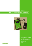
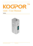
Ver 1.02 UVe-LUX Operators Manual NDT Consultants Ltd Middlemarch House, Siskin Drive, Coventry +44 (0)2476 511151 [email protected] 24/11/2009 Revision History Version 1.00 1.01 1.02 Date 20/11/09 23/11/09 24/11/09 Page All 1,4 1 5 Description 1st draft Typos and spelling mistakes corrected. References to visible light replaced with WL (white light). Menu system section revised UVe-LUX Operators Manual ver 1_02.docx ii 24/11/2009 Table of Contents 1 Introduction .................................................................................................................................... 1 2 System Components ....................................................................................................................... 1 2.1 Sensor housing ........................................................................................................................ 1 2.2 Meter housing ......................................................................................................................... 2 2.3 Buttons .................................................................................................................................... 2 2.4 The Battery.............................................................................................................................. 3 2.5 Display ..................................................................................................................................... 4 2.5.1 Measurement Display ..................................................................................................... 4 2.5.2 Menu system................................................................................................................... 5 UVe-LUX Operators Manual ver 1_02.docx iii 24/11/2009 1 Introduction The UVe-LUX is a compact, lightweight and robust meter specifically designed for the nondestructive testing environment. The meter is a dual white-light (WL) and ultra-violet (UV) meter designed to give simultaneous readings of both WL and UV. The meter has the following specification: Single sensor head measures UV and white light at the same time. 320 x 240 pixel 2.4” colour display. Dimmable display to extend battery life. High contrast ratio OLED screen (over 30 x greater than a TFT-LCD in dark conditions and over 12 x in sunlight). 180°(UD)/180°(LR) viewing angle (over 3 x viewing angle of TFT-LCD in both viewing planes). Auto-ranging on both WL and UV scales. Menu driven setup and multi-function buttons. ‘Auto Hold’ function to record maximum readings. Adjustable auto-power down to conserve battery life. Meets the requirements for non-destructive testing viewing conditions for penetrant and magnetic particle inspections (ISO 3059). Measurement units - WL: lux or fc, UV: μW/cm² Measuring range - WL: 0.1 to 5000 lux, UVA: 1 to 10,000μW/cm² Accuracy - WL: better than 5%, UV: better than 5% 2 System Components The system consists of a sensor housing containing both the WL and UV sensors, and the meter housing containing the main system components such as the screen, battery and user interface. Both the sensor housing and the meter housing are constructed out of reinforced ABS plastic and are rated to IP64 for moisture and dust ingress. The two housings are linked together with 600mm of flexible screened cable for ease of use. 2.1 Sensor housing The sensor housing contains the individual WL and UV detectors in one handy unit. The active area of the sensor housing is the circular glass panel on the front of the housing. Care should be taken to ensure that the glass panel remains clean and is not damaged in any way as any dirt or damage to the glass panel will affect the accuracy of the meter. Should the panel require cleaning a damp cloth with a small amount of detergent can be used the wipe the panel, and a dry, lint-free cloth can then be used to dry the panel. Abrasive cleaners and solvents should NOT be used as they may cause damage to the unit. Should the panel become damaged, the whole meter should be returned to Figure 1 Sensor housing UVe-LUX Operators Manual ver 1_02.docx 1 24/11/2009 the manufacturer for repair and re-calibration. 2.2 Meter housing The Meter housing contains the display screen, buttons and battery for the unit. The meter housing is rated at IP64 for moisture and dust ingress and should it need cleaning it can be cleaned with a damp cloth and using mild detergent. Figure 3 Display Figure 2 Meter housing Figure 4 Buttons 2.3 Buttons On/Off button: Pressing this button when the unit is off will switch the UVe-LUX on. Holding this button down when the system is on will switch the system off. Pressing this button while the system is in measurement mode will reset the max WL and max UV readings. Pressing this button while the system is in menu mode will select the currently highlighted menu function. Down button: Pressing the down button in measurement mode makes the screen darker by one count. Holding this button down in measurement mode will keep decreasing the screen brightness until the button is released. Pressing the down button in menu mode will cycle down through the menu options. Holding the button down in menu mode will keep cycling down through the menu options. Up button: Holding this button down and then pressing the On/Off button when the unit is powered off and keeping it held down until after the welcome screen has appeared will enter menu mode. In measurement mode pressing this button will lighter the screen by one count. UVe-LUX Operators Manual ver 1_02.docx 2 24/11/2009 Holding this button down in measurement mode will keep increasing the screen brightness until the button is released. Pressing the up button in menu mode will cycle up through the menu options. Holding the button down in menu mode will keep cycling up through the menu options. 2.4 The Battery The UVe-LUX is powered by a single 9V PP3 style battery (K9V X/522 MX/MN 1604 A1604 6AM6 4022/1604A/6LR61). The battery is held in its own compartment which is accessible by unscrewing the two screws holding the battery housing cover on the rear of the meter housing. Once the cover has been removed the battery can accessed. The battery can only be fitted in one orientation with the positive terminal of the battery being connected to the ‘+’ clip in the battery compartment. The battery should only be fitted in the orientation described, if the battery is forced in the wrong way round damage may occur to the UVe-LUX meter. The battery housing cover should then be replaced and screwed back down. It recommended that the battery should only be replaced with a new battery and not a previously used one. Figure 5 Battery compartment With typical usage the battery should last for approximately 3 months, and should last over 2 years with the unit powered off. It is recommended to replace the battery every 12 months and to remove the battery when the UVe-LUX is to be stored for a long period of time without use. When the battery indicator (see display section) is reading ‘LOW’ the battery should be replaced. The meter may not give accurate readings when the battery is low. UVe-LUX Operators Manual ver 1_02.docx 3 24/11/2009 2.5 Display The meter is fitted with an OLED display that gives a much higher contrast and superior viewing angle than traditional TFT or LCD displays. The display is protected behind a protective plastic cover, but care should still be taken to protect the screen area from blows or scratches or other damage. In normal operation when the unit is powered up, the first screen to appear is the Logo screen, followed by the Splash screen. The Logo screen contains information about the meter, including the serial Figure 6 Viewing angle number and date of last calibration for the unit. Keeping the ON/OFF button held down during power on will pause the meter at the splash screen until the button is released. Figure 7 Logo Screen Figure 8 Splash Screen 2.5.1 Measurement Display When the unit is powered up it will normally enter the measurement display after the Splash Screen. The measurement display contains five components: Battery level – This gives an indication of the state of the battery life. WL reading- this is the current reading for the white light sensor (this reading is rounded). WL max – this is the maximum value the meter Figure 9 Measurement Display has observed for white light (this reading is absolute). This reading is reset when the ON/OFF button is pressed. UV reading- this is the current reading for the UV sensor (this reading is rounded). UV max – this is the maximum value the meter has observed for UV (this reading is absolute). This reading is reset when the ON/OFF button is pressed. If the meter is exposed to light levels greater than it’s designed range the meter will saturate. When the meter is saturated it will display “>5000” “>10000” or “++++” in red to indicate that it has saturated. The meter will return to normal operation once the light levels have returned to the meters design range. UVe-LUX Operators Manual ver 1_02.docx 4 24/11/2009 2.5.2 Menu system The menu system is entered by holding the UP-button down while the system is powered off and then pressing the On/Off button and keeping the UPbutton held down until after the welcome screen has appeared. Once in menu-mode the UP and DOWN keys can used to scroll through menu items and pressing the ON/OFF key is used to select menu items. Figure 10 Main menu screen Holding the ON/OFF key down for several seconds in menu mode will power the system down. Brighter Brightness Darker Set autooff Back Settings menu Main menu LUX Calibration menu Set units Foot Candles Programing menu Back Back About Power Down Figure 11 Menu Hierarchy UVe-LUX Operators Manual ver 1_02.docx 5 24/11/2009 Main menu – This is first menu entered when the meter enters the menu mode. Settings menu – Contains the settings for changing meter operation. Brightness – enters brightness menu. Brighter – makes screen brighter. Figure 12 Settings menu Darker – makes screen darker. Figure 13 Brightness menu Back – returns to Settings menu. Set auto-off – Sets the auto-power off time (between 20s and 6000s) Figure 14 Set auto-off Set units – Enters Set Units menu. LUX – Selects LUX as white light units. Foot Candles – Sets Foot Candles as white light units. Back – returns to settings menu. Figure 15 Set Units Back – returns to Main menu. Calibration menu – not accessible to user. Programming menu – not accessible to user. About – Displays information about meter. Power Down – powers down meter. UVe-LUX Operators Manual ver 1_02.docx 6 24/11/2009