1
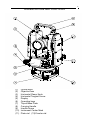
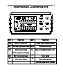
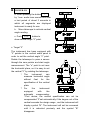
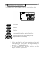
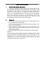
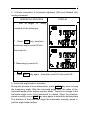
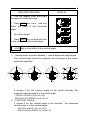
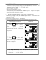
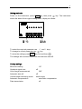
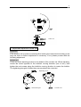
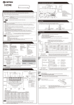
1
Operators’
Manual
Electronic Theodolite FET 420K
2
IMPORTANT!
READ THIS BEFORE USING YOUR INSTRUMENT
1. Make a full check for the instrument before using it. Be sure that the
instrument’
s functions, power, original settings and revised
parameters meet your requires before you operate it.
2. To avoid direct sunlight to the instrument’
s lens, never leave the
instrument exposed to extreme heat longer than necessary, or it
could affect the instrument’
s accuracy..
3. When mounting or dismounting the instrument to or from the tripod,
hold the instrument by one hand, turn the central screw on the tripod
by the other hand to prevent the instrument from falling. If the
instrument must be carried on the tripod, hold the instrument as
vertically as possible. Never carry the instrument horizontally over
your shoulder. Any long distance transport should be done with the
instrument in the carrying case.
4. Put the instrument in the carrying case to avoid extrusion, crash and
shock during the transportation. Shockproof cushion should be
necessarily put inside the carrying case during the long distance
transportation.
5. Clean the dirt on the surface of the organic glass and plastic by floss
or brush after using the instrument. Dry the instrument in time after
use in the rain.
6. Do not use harsh chemicals to clean the surface of the organic glass
and plastic components. A water dampened rag is all that is
necessary.
7. Use absorbent cotton or lenses tissue to clean the exposed optical
parts. Handkerchief, clothes or other things like that are forbidden for
cleaning.
8. The instrument should be stored in an area of low humidity and good
ventilation, where the temperature will not exceed 110º F(45ºC). It
should be necessary to replace the desiccant regularly in the
carrying case.
9. Always remove the batteries before storing the instrument.
10. Please contact our corporation if the instrument’
s functions appear
abnormal. Non-professional repairers are forbidden to disassemble
the instrument.
3
CONTENTS
USAGE
NOMENCLATURE and FUNCTIONS
1. Nomenclature
2. Display Marks
3. Operating keys
PREPARATION BEFORE MEASUREMENT
1. Mounting to prepare for measurement
2. Power on
3. Battery state indication
4. Battery replacement
ANGLE MEASUREMENT
1. Left/Right Observation
2. Target Aim
3. Horizontal Angle 0set (0SET)
4. Measuring Horizontal and Vertical angle (HR? VH or HL? V)
4
ANGLE MEASUREMENT
5. Horizontal Angle Locked----Unlocked (HOLD)
6. Measuring Zenith Distance, Vertical Angle and Height Angle
7. Grade Percent Mode (Grade Angle Measurement)
8. Repeating Angle Measurement
OTHER FUNCTIONS
1. Measuring distance by crosshair of the telescope
2. Incline Correction Function
3. Quadrant Buzzing Function
4. Illumination and Timing Close Function
FUNCTIONS SETTINGS
ERRORS LIST
ASSEMBLY and DISASSEMBLY of BASE PLATE
CHECK and ADJUSTMENT
TECHNICAL SPECIFICATIONS
5
USAGE
Electronic
Digital
Theodolite
FET
420K
series
has
adopted
increment-mode digits system for angle measurement.
The resolving power of horizontal and vertical angles can reach 10”
.
The precision of angle measurement can reach 20”
.
Electronic Digital Theodolite FET 420K can be widely used in 3-4 class
national triangle control measurement, precise lead measurement,
engineering measurement for mine? railway? water conservancy and so
on, landform measurement, and also could be used in the assembly of
the large machinery facilities.
The displays are illuminated so as to make it convenient to operate in
the darker environment.
6
NOMENCLATURE AND FUNCTIONS
(1)
(2)
(3)
(4)
(5)
(6)
(7)
(8)
(9)
(10)
(11)
Optical sight
Objective lens
Horizontal Clamp Knob
Horizontal Tangent Screw
Display
Operating keys
Tripod Base Plate
Carrying Handle
Handle Screw
Instrument Center Mark
Plate vial (12)Circular vial
7
(1) Focusing Knob
(2) Optical plummet
(3) Communication Plug
(4) Footscrew
(5) Battery Compartment
(6) Telescopes Eyepiece
(7) Vertical Clamp Knob
(8) Vertical Tangent Screw
(9) Clamp of Tribrach
8
DISPLAY and DISPLAY MARKS
DISPLAY
1
2
3
4
5
6
Ht
INDICATIONS
General
value
of
repeated values
V
Vertical angle
Number of repeated
measurements
AVG Average of repeated
measurements
HR
Right horizontal angle
HL
Left horizontal angle
DISPLAY
7
8
9
10
11
12
TILT
F
G
%
REP
BAT
INDICATIONS
Incline compensator function
Optional Function keys
Angle unit GON
Vertical slope %
State
of
repeated
measurement
Battery state indication
9
OPERATING PANEL and OPERATING KEYS
KEY
FUNCTION
FUNC
Optional function keys
REP
V/%
KEY
Lighting switch for display window
Repeated angle measurement HOLD
Vertical angle display
FUNCTION
R/L
Hold horizontal angle
Option of left/right horizontal angle
Vertical angle/percent display
0SET
v
0SET for horizontal angle
Move cursor leftward
Power Switch
w
r
Move cursor rightward
Alter the number cursor indicated
10
PREPARATION FOR MEASUREMENT
1. MOUNT INSTRUMENT and PREPARE FOR MEASUREMNET
Level and center the instrument precisely to get the best
performance.
a. Mount tripod
Firstly place the tripod legs to a suitable spot and tighten the locking
device.
b. Mount instrument
Attach the instrument to the tripod carefully, then move instrument
by loosening center screw. Fasten slightly the center screw when
the plummet is centered over the sign.
c. Roughly level the instrument with the circular vial
? Use footscrew 1, 2 to move the air bubble in the circular vial
so it is centered left to right.
? Use footscrew 3 to move the air bubble to the center of the
vial.
d. Fine tune level the instrument with the plate level
?
?
?
Loosen horizontal clamp knob. Turn the instrument to place
the plate vial parallel with the footscrew 1, 2. Center the
bubble using these two footscrews. Attention: Turn the two
foot screws reversely when you adjust them.
Turn the instrument 90°and center the bubble using level
screw 3.
Repeat step ? ? ? every time the instrument is turned 90°to
center all the bubbles in these positions.
11
?
Return to the original position in step A. Rotate the
instrument 180°. The plate vial is mounted correctly and the
instrument is leveled nicely if the bubble is centered no
matter the instrument is rotated in any direction.
? Please pay attention to the relations between the turning
direction of the level screws and the moving direction of
the bubble. Adjust plate vial if the bubble is not centered in
step 4.
e. Centering the instrument using the optical plummet
Adjust the eyepiece according to the observer’
s eyesight, then move
the instrument by loosening center screw until the image of the sign
on the ground centered in the circle of the reticule. Move the
instrument carefully in case it appears incline.
f. Final leveling of the instrument
Level the instrument precisely in the similar way to step ? . Rotate
the instrument to see if the bubble in the plate vial is centered, then
tighten the center screw.
12
2.
FA
POWER
ON
a. When pressing the button
?
by 1 sec. audio tone sounds and after
a test period of about 2 seconds in
which all segments are displayed
instrument is ready for use.
b.
Move telescope to activate vertical
angle reading.
c. Push
V/%
button to
show vertical angle “
0”point.
c. Target “
0”
The instrument has been equipped with
“
0”pointer in the vertical scale panel in
order to set the vertical angle “
0”point.
Rotate the telescope to pass a sensor
through the zero pointer and start angle
measurement. The “
o”point is set near
the horizontal place, so it is easy to set
the vertical “
0”by rotating the telescope.
? The
instrument
can
measure horizontal angle
without 0set for the
specification of the vertical
plate.
? For
the
instrument
equipped
with
the
automatic compensatory
“
0”
set device, the vertical specification can not be
compensated “
0”
set automatically if the degree out of the
vertical exceeds the design range , and the instrument will
display symbol “
B”
. The instrument will not be recovered
until it is releveled precisely and the symbol “
B”
disappears.
13
3.
BATTERY STATE INDICATION
The battery symbol on the display shows the current battery state.
Full power
Effective
Effective
Low power but effective, replace the battery
Instrument will shut off automatically shortly.
Replace batteries immediately.
?
?
Battery operating time will vary depending on type and
brand and quality of the battery. We suggest always to
secure for a 2nd standby battery set.
For any questions about replacing batteries, see this
chapter “
4. battery replacement”
.
14
4. BATTERY REPLACEMENT
a. Removing the battery
Push down the press button and remove the battery compartment.
b. Battery replacement
? Push down the hook to pull cover board away from the
battery compartment.
? Replace the old batteries by new ones.
Take care of correct polarity.
? Snap the battery cover back into place.
c. Mounting Battery Compartment
Slip the projection on the bottom of the battery compartment into the
slot. Push the press button on top of the battery compartment until it
clicks into place.
15
ANGLE MEASUREMENT
1.
Vertical Plate left/right observation
“
Plate left”means the vertical plate is on the left side by the
telescope when the observer faces the eyepiece. “
Plate right ”means
the opposite to the “
plate left”
. Taking the average reading of t he
“
plate left”and “
plate right”as the observation value can effectively
remove the corresponding effect on the observer from the system
errors in the instrument. Therefore, turn the telescope 180 °for the
“
plate right”observation after the accomplish of the “
plate left”during
the observation of the horizontal and vertical angle.
2.
Target aim
? Point the telescope at the brightness and focus the eyepiece until
the crosshair can be seen clearly.
(Turn the focusing knob in the direction facing the observer, t hen
focus in reverse direction.)
? Aim at the target coarsely using the coarse aiming device. The
definite space can be kept between the device and the observer
when aiming coarsely.
? Focus the target by turning the focusing knob on the telescope.
Attention:
The visual errors of the target and retic ule crosshair will be created
in the horizontal and vertical direction if the telescope or the
eyepiece are not focused precisely, which can result in the
measuring errors. Focus for the telescope and eyepiece sho uld be
necessary to remove the visual errors.
16
3.
Horizontal angle 0set (0SET)
OPERATING PROCESS
?
DISPLAY
Aim at target “
A” using
crosshair of the telescope.
? Press 0SET key once to set reading
of horizontal angle 0°00’
00”
? 0SET key is only effective to the horizontal angle.
? Horizontal angle can be set “
0”at any time except the holding
state(HOLD key).
4. Measuring horizontal and vertical angle (HR? V or HL? V)
Horizontal rightward turning increment and Vertical angle
measurement.( HR? V)
OPETATING PROCESS
? Aim at target “
A”using crosshair
of the telescope.
?
Press 0SET key once to set reading
of horizontal angle 0°00’
00”
? Turn instrument clockwise and
aim at the second target “
B”to get
its horizontal and vertical angle.
DISPLAY
17
4. 2 Mode conversion of horizontal rightward (HR) and leftward (HL)
turning increment
OPERATING PROCESS
?
DISPLAY
Aim at target “
A” using
crosshair of the telescope.
? Press
R/L
key, transform
horizontal angle mode HR into
the mode HL.
? Measuring by mode HL.
? R/L key is of no effect to the vertical angle. ?
? Press R/L key again, transform mode HL into mode HR. .
5. Horizontal angle locked --unlocked
During the process of level observation, press HOLD key once to keep
the measuring angle. After the horizontal angle held, the value of the
horizontal angle on the display window blinks. There is no change to the
horizontal angle even if the instrument is rotated. When the direction
aimed correctly, press HOLD key once again to unlock the holding state.
The direction of the horizontal angle the instrument currently aimed is
just the angle locked before.
18
OERATING PROCESS
DISPLAY
? Turn the tangent knob and place
the required horizontal angle.
? Press HOLD key once , hold and
flicker the value of the horizontal
angle.
? Aim at the target.
? Press HOLD key, no blink and hold
to the value of the horizontal angle
?
HOLD key is of no effect to the vertical angle.
?
Measurement of zenith distance ? vertical angle and height angle
The vertical angle should be originally set according to the needs
before the operation.
6. 1 ZENITH DISTANCE
If choose 0 ° for the vertical an gle as the zenith direction, the
measured vertical angle V is the zenith angle.
ZENITH DISTANCE V=(L+360°-R)/2
SPECIFICATON ERROR i=(L+R-360°)/2
6. 2 VERTICAL ANGLE
If choose 0°for the vertical angle in left direction , the measured
vertical angle V is the vertical angle.
VERTICAL ANGLE V=(L+180°-R)/2
SPECIFICATION ERROR i=(L+R-540°)/2
19
6. 3 HEIGHT ANGLE
If choose 0°for the vertical angle in both left and right direction , the
measured vertical angle V is the height angle.
HEIGHT ANGLE V=(L+R)/2
SPECIFICATION ERROR i=(L–R)/2
ATTENTION: If SPECIFICATION ERROR |i|=10?, inspect and adjust
according to the instruction manual.
7. SLOPE PERCENT MODE (slope angle measurement)
Measuring in angle mode, the vertical angle could be transformed into
percent of grade.
The percent of grade value = H/D*100%
The range of grade percent is from the horizontal direction to ±45°.
OPERATING PROCESS
? Press
V%
from
vertical
DISPLAY
key to switch
angular
measurement shown in degrees
to percent.
? Press
V %
key once again
back to the angular measurement
shown in degrees.
? Any angle exceeding 100% the percent of grade will be
shown as
“
- - - - -”on
the display
20
8.
ANGULAR REPEATED MEASUREMENT
OPETATION PROCESS
DISPLAY
? Press FUNC key
?
Press
REP
key to put the
instrument in repeated mode
? Aim at target A and press 0SET key
once to set the first target reading 0°00’
00”.
? Turn the horizontal tangent knob to aim
at the second target B.
? Press HOLD key to hold the horizontal
angle and store in the instrument.
? Turn the horizontal tangent knob to aim
at the target A again. Press R/L key to
release the angle and keep the state.
? Turn the horizontal tangent knob to aim
at the target B again.
? Press HOLD key to hold the horizontal
angle and store in the instrument. Double
and average angle-value will be shown on
the display.
? Repeat step ?
?
according to
measuring requires.
? Back to normal angular measurement,
press FUNC key, then press HOLD key.
The reading of horizontal angle could reach at least ±2000°00’00”when
measuring in “
Plate left”or “
Plate right”mode. The five-seconds reading could
reach at least ±1999°59’59”
.
? The repeated measurement should be limited within 15 times when the
instrument is in the repeated mode, otherwise an error will be shown.
? Error E04 will be shown on the display when measured error every time exceeds
or equals ±30”during the repeated measurement, go back to step ? .
? Press FUNC key, then press HOLD key to back to the original state.
?
21
FUNCTION SETTING
SETTING INSTRUCTION
The instrument supply multi-functions for your option to meet different requires of
measuring configuration.
ITEM SETTING
Step
Item
Minimum
reading
1
2
3
4
5
Quadrant
signal tone
7
Change
between
and 20”
Parameter setting
Setting 0
Setting 1
10”
Confirm every
90º by
signal tone
10?
20“
Setting 0
Setting 1
off
on
Change
Unit of angle between DEG,
measurement GON, MIL
Setting 0
Setting 1
Setting 2
Setting 3
DEG
GON
MIL
DEG
Set interval for
automatic
shut-off
Setting 0
Setting 1
Setting 2
Setting 3
off
10min
20min
30min
Auto shut-off
Measuring
Set “
0”point of
mode
for vertical angle
vertical angle
Automatic
compensation
6
Instruction
Data
transmission
Set incline
correction
function
Set
data
transmission
function
Setting 0
Setting 1
Vertical
angle
(0 in
horizontal)
Zenith
Angle
(0 in
zenith)
Setting 2
Height
Angle „
+/-„
(0 in horizontal)
Setting 0
Setting 1
off
on
Setting 0
off
Setting 1
on
22
Setting methods
Power on the instrument, press FUNC key, then press
key. The instrument
enters the state of the original setting mode, display as follows:
To select the required parameter use
To change to correct parameter use
and w keys.
v
key.
To store the settings press FUNC key first and then
.
The settings will be stored even if the unit has been shut off.
Factory settings
Minimum reading
Quadrant signal tone
Unit of angle measurement
Automatic shut-off
Vertical angle measuring-mode
Automatic compensation
Data transmission
10?
off
360°
off
zenith angle
automatic compensation
off
23
ERROR DISPLAY
DISPLAY
B
ERROR CONTENT AND DISPOSAL
Vertical compensator out of compensating range.
Level the instrument again
E00
Collimate rotating too fast. Press 0SET key to set 0.
If “
E00”is shown again instrument needs to be repaired.
E01
Telescope turning too fast, press V/% key to set 0 for the vertical
plate specification.
E02
Interior error of the horizontal angle measuring system. Power on
the instrument again. If error is shown again instrument needs to be
repaired.
E03
Interior error of the vertical angle measuring system.
If error is shown again instrument needs to be repaired.
E04
Difference between every value exceeds 30? during the angle
repeated measurement, press 0SET key and measure repeatedly.
E05
Times of angle repeated measurement exceed 15, press key and
measure repeatedly.
E06
Errors during the process of the vertical angle 0set or adjusting 0set
when the clamp angle to the horizon exceeds 45°. Need adjusting
repeatedly.
Attention:
Check fully every part of the instrument and see whether the operation coincide with
the procedures after the error appears.
If the error code is still shown after many checks please send the instrument for
repair.
24
MOUNT and DISMOUNT of THE BASE PLATE
Loosening or tightening turning handle can easily mount or dismount the instrument
to or from the base plate.
DISMOUNT
? Turn the fixed pull handle 180 degrees counterclockwise.
? Hold the base plate by one hand, bring up the instrument using the carrying
handle by the other hand.
MOUNT
? Bring up the instrument by hand and aim the orientation block at the
orientation slot. Mount the instrument on the base plate carefully.
? Tighten the fixed pull handle on the base plate.
CHECK and ADJUSTMENT
Adjustment Instruction
? Adjust the eyepiece and focus it precisely to avoid the visual errors before the
observation through telescope.
? Adjustment should be carried out one by one according to the following steps
because each step’
s adjustment is based on its former one’
s result. Disorder the
steps will default the adjustment.
? Do tighten the screw after the adjustment. The strength applied should be
suitable because overtighten will damage the thread.
? After the adjustment do repeat the inspection to make sure that the adjustment
has been well done.
1.Inspect and Adjust the Plate Vial
Inspection
? Make the plate vial parallel with two footscrews among the three ones. Center its
bubble by adjusting the two footscrews.
? Turn the instrument 180º and observe the bubble. Adjustment is needed if the
bubble is not centered.
Adjustment
? Calibrate the plate vial by using the adjusting pin to adjust its screw to make the
bubble move center-oriented halfway of the offset.
? The other halfway will be offset by performing the adjustment of the two leveling
screws, which are parallel with the long vial.
? Turn the instrument 180° nd check if the bubble is centered. If not, repeat the
steps mentioned above till the bubble is centered.
? Turn the instrument 90° nd center the bubble by adjusting the third leveling screw.
Repeat the checking and adjustment steps above until the bubble stays centered no
matter in any direction.
25
Offset 1/2
? Inspect and Adjust the Circular Vial
Inspection
If the circular vial is centered correctly after leveling the instrument according to the
long vial, then no further adjustment is necessary. If not, please proceed with the
following adjustment.
Adjustment
There are three adjusting screws on the bottom of the circular vial. When adjusting,
loosen the screw opposite to the bubble’
s moving direction (one or two), then
tighten the rest screws along the bubble’
s moving direction to center the bubble.
The tightening strength of these three screws should be coincided.
Adjusting screw
The bottom part
Circular vial
26
? The Telescope Reticule
Inspection
? Mount the instrument on the tripod and level it carefully.
? Set target point A 50 meters to the instrument, aim at point A by the stadia hairs.
? Turn the telescope and observe point A whether it moves along the vertical hair
? If point A moves along the vertical hair, that means the vertical hair is
perpendicular to the horizontal axis, then no further adjustment is necessary.
? Adjustment is necessary if the point A moves deviated from the vertical hair.
A
A'
A
A'
Fixing screw
Adjusting screw
Adjustment
? Turn counterclockwise and remove the reticle cover between the eyepiece and
focusing knob, This will expose four reticle fixing screws.
? Loosen these four fixing screws equably by screwdriver. Turn the reticle base
around the visual axis to set point A on the vertical hair.
? Tighten these four fixing screws equably and observe whether any deviation
appears when point A moves along the vertical hair. If not, the adjustment is over.
? Assemble back the reticle cover to its original position.
27
? Perpendicular Degree of the Visual Axis to the Horizontal Axis
Inspection
? Set two obvious targets as high as the instrument about 100 meters apart with
the instrument in their center point.
Level the instrument precisely and power it on.
? Aim at target A using crosshair of the telescope plate-leftward.
? Loosen the vertical braking knob. Rotate the telescope around the horizontal axis
180° to aim it at the opposite direction.
? Aim at target B with the same distance to target A
? Rotate the horizontal braking knob to turn the instrument 180°.
Aim at the target A, then lock the knob.
? Rotate the vertical braking knob to turn the instrument 180°. Aim at the target C.
Target C should be superposed to target B. If not, adjustment is necessary.
28
Adjustment
?
?
?
?
Remove the reticule cover between the eyepiece of
the telescope and the focusing knob.
Set up point D between point B and C. The distance of
DC should be a quarter of BC. Adjust the two
adjusting screws to move the reticule to have its cross
aim at point D.
Repeat above inspection and adjustment steps until B
and C are superposed.
Assemble back the reticule cover to its original
position.
Loosen one screw if the vertical hair of the crosshair
Adjusting screw
should be moved, then tighten the other one in the
same turn. Loosen the screw counterclockwise and tighten in the clockwise
direction. The turn should be as little as possible no matter loosen or tighten.
? After the adjustment above, the zero reset of the vertical angle should be carried
out.
?
? Automatic compensation of the vertical axis
The instrument is equipped with the electronic incline sensor device, which can
compensate the vertical axis.
Check
? After mounting and leveling the instrument, coincide the point of the telescope
with the line between the center of the instrument and its any level screw. Then
tighten the horizontal braking knob.
? Set zero for indication of the vertical plate after power-on. Tighten the vertical
clamp knob and the instrument displays the current value of the vertical angle the
telescope pointed.
? Turn the footscrew in one direction till 10 mm or so (circle distance). The value of
vertical angle also changes correspondingly till it disappears and the symbol “
b”is
shown, which means the incline of the instrument’
s axis has exceeded out of the
compensated range. When turning the leveling screw in reverse, the instrument
returns to display the vertical angle (repeat testing and observe the changes on the
critical point), which means the compensation device works well.
Adjustment
When the compensation doesn’
t work well or works abnormally, send to the factory
for repair.
29
? Vertical plate angle specification ( “
i”angle) and its 0 set
Check
? After mounting and leveling, power on the instrument. Aim the telescope at any
clear target A to get the reading L the vertical plate leftward.
? Turn the telescope and aim at target A again to get the reading R the vertical
plate rightward.
? If vertical angle is in the zenith angle mode, then i=(L+R- 360°) /2.
If in the vertical angle mode, then i=(L+R-540°)/2.
If in the height angle mode, then i=(L–R)/2
? If the specification errors |i|=20?, 0 reset of the vertical plate is necessary.
Adjustment
? After leveling precisely, power on the instrument. Press V/% key once, the
request of zero-set of vertical angle is displayed.
? Rotate the telescope slowly in the horizontal direction of the left vertical plate
until the vertical angle is displayed. Press FUNC key once, then press V/% key. The
instrument displays as follows:
? Rotate the instrument and precisely aim at the clear and stable target A as high
as the instrument in the distance. Press 0SET key, the instrument displays as
follows:
? Turn the telescope and aim the right of the vertical plate at the same target A.
Press 0SET key and the instrument backs to the angle measurement mode after
the setting.
? Check the specification error i to see whether it accords with the requires. If not,
check whether do the right adjusting procedures, or whether the aim of the
target is precisely, etc.
? Send to the factory for repair after operations repeated many times without any
effect.
30
? Check and Adjust the optical plummet
To superpose the optical axis of the plummet and the vertical axis, adjustment for
the plummet is neccessary, otherwise the vertical axis will not be on the true anchor
point when the aim begins.
Inspection
? Mount the instrument on the tripod and place a sheet of paper with a cross on it
under the instrument.
? After adjusting the focus of the optical plummet, move the paper to center the
cross of the crosshair in the field of view.
? Turn the collimator 180º, observe the superposed degree of the center mark and
the cross.
? If the center mark of the optical plummet and the cross of the hair keep
superposed when turning the collimator, adjustment is unnecessary. If not, adjust it.
Adjustment
? Turn counterclockwise and remove the adjusting screw cover between the
optical centering device and the focusing knob.
? Fix the sheet of paper with the cross on it and mark the fallen point of the center
mark each time when the instrument turns 90º, shown as the illustration: point A, B,
C, D
Adjusting screw
Optical plummet
? Line up points on the cross AC and BD to get the point of their intersection O.
? Regulate the four adjusting screws on the optical plummet with the adjusting pin
to superpose the center mark and point O.
? Other adjustment
Adjust the two leveling screws on the base plate if the screw loosens. The
tightening strength should be suitable.
31
Technical Specifications
Telescope
Image
erect
Magnification
30×
Objective aperture
45mm
Resolving power
3’
’
Field of view
1º30?
Minimum focus
1.4m
Stadia multiplied by constant
100
Stadia plus constant
0
Stadia precision
=0.4%L
Length
157mm
Angle measurement
Method
Incremental
Diameter of circle
71mm
Minimum reading
10?/20? (2/5mgon)
Angle measurement units
360º/400gon/6400mil,optional
Precision
20? (5 mgon)
Level sensivity
Plate vial
30?/2mm
Circular vial
8'/2mm
Compensator
Electronic incline sensor
Vertical angle compensation
Compensation range
±3'
Precision
1?
Optical plummet
Image
erect
Magnification
3×
Field of focus
0.5m~ 8
Field of view
5°
32
Display
LCD-Display
2 sides
Data input and output
Plug (one)
RS232
Power supply
Alkaline batteries
4 x 1.5 V AA
Operating time
15 hrs
Operating temperature
- 20°~ + 45°
Weight
4 kg
09-2004