1
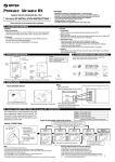
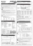
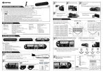
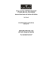
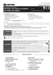
OUTER DIMENSIONS AND PART NAMES
36(1 7/16")
[mm (inch)]
7.5(5/16")
267(10 1/2")
125(4 15/16")
43(1 11/16")
38(1 1/2")
61(2 3/8")
5919220 MAR 2012
X-ZONE
MANUFACTURER'S STATEMENT
STATEMENT
MANUFACTURER'S
WARNING
CAUTION
NOTE
(9)
Disregard of the warning symbol can cause improper operation which may cause death
or serious injury.
(3)
Disregard of the caution symbol can cause improper operation which may cause injury of a
person or damage the object.
(4)
(5)
BLUE-ZONE
1. This product is a non-contact switch intended for header mount or wall mount for use on an automatic sliding door.
Do not use for any other applications.
2. When setting the sensor's detection area, make sure that there is no traffic around the installation site.
3. Before turning the power ON, check the wiring to prevent damage or malfunction of equipment connected to
the product.
4. Only use the product as specified in the operation manual provided.
5. Be sure to install and adjust the sensor in accordance with the local laws and standards of the country in which
the product is installed.
6. Before leaving the installation site make sure that the product is operating properly and instruct the building
owner/operator on proper operation of the door and the product.
7.The product settings can only be changed by an installer or service engineer. When changed, the
changed settings and the date shall be registered in the maintenance logbook accompanying the door.
WARNING
When dipswitch 15 is set to ON, the blue-zone area, that provides extra safety over the threshold, is activated.
In case the blue-zone function is not required, set dipswitch 15 to OFF.
Do not set the 2nd row overlapping the threshold regardless of the setting of dipswitch 15.
2nd row
1
The following conditions are not suitable for sensor installation.
-Fog or exhaust emission around the door
-Wet floor
-Vibrating header or mounting surface
-Moving objects, steel plate, emergency lights or illumination in the detection area or in vicinity
-Highly reflecting floor or highly reflecting objects around the door
-Grating floor
H : Height from the floor to the bottom of the header
Y : Distance between the bottom of the header and the sensor
X : Distance between the door and the mounting surface
Header
Safety output
: Form C relay
50V 0.3A Max.(Resistance load)
Output hold time
: <0.5 sec.
Response time
: <0.3 sec.
Opetating temperature : -35 to +55°C (-31 to 131°F)
Operating humidity
: <80%
IP rate
: IP54
Weight
: 320g (11.2oz )
Accessories
: 1 Operation manual
2 Mounting screws
1 Mounting template
1 Area adjustment tool
1 Cable 3m (9'10")
1 Narrow lens
Operation indicator table
Status
Operation indicator color
Set-up
Yellow blinking
Stand-by (installation mode)
Yellow
Stand-by (operation mode)
Green
Blue-zone (1st row) detection*2
1sec.
NOTE
CAUTION
2
Orange
Signal saturation
Slow green blinking
Sensor failure
Fast green blinking
4
DETECTION AREA
AIR
Mounting height : 2.2m(7'2")
Angle adjustment : +6°
Sensitivity : M
: Emitting spots
A
Mounting
surface
B
Blue-zone(1st row)
C
2nd row
D
: Detection area
E
F
3rd row
G
1000(3′3")
I
2000(6′6")
0
Microwave
Mounting height : 2.2m(7'2")
Vertical adjustment : +35°
Sensitivity : H
Speed of detection object
: 50mm / sec.
: Detection area
(Wide area)
: Detection area
(Narrow area)
H
1000
(3′3")
: Emitting spots
(can be eliminated)
1000
(3′3")
AIR emitting area
The chart shows the values at depth angle +6°
[m(feet,inch)]
3.00 (9'10")
0.08 (3")
0.11 (4")
0.34 (1'1")
0.53 (1'9")
0.89 (2'11")
1.81 (5'11")
2.79 (9'2")
3.50 (11'6")
0.09 (4")
0.12 (5")
0.39 (1'4")
0.61 (2')
1.38 (3'5")
2.11 (5'11")
3.25 (10'8")
2.00 (6'6")
0.05(2")
0.07(3")
0.23 (9")
0.35 (1'2")
0.59 (1'11")
1.21 (3'12")
1.86 (6'1")
2.20 (7'2")
0.06 (2")
0.08 (3")
0.25 (10")
0.39 (1'3")
0.65 (2'2")
1.33 (4'4")
2.05 (6'9")
2.50 (8'2")
0.07 (3")
0.09 (4")
0.28 (11")
0.44 (1'5")
0.74 (2'5")
1.51(4'11")
2.32 (7'7")
2.70 (8'10")
0.074(3")
0.10 (4")
0.31 (1')
0.48(1'7")
0.80 (2'8")
1.63 (5'4")
2.51 (8'3")
2.52(8'3")
2.78 (9'1")
3.15 (10'4")
3.40 (11'2") 3.79 (12'5") 4.42 (14'6")
The actual detection area may become smaller depending on the ambient light, the color / material of
the object or the floor as well as the entry speed of the object.
The sensor may not be activated when the entering speed of the object or a person is slower than
50mm / sec. or faster than 1500mm / sec.
0.13 (5")
0.12 (5")
0.10 (4”)
0.09 (4”)
-
2.80 (9' 2")
No limit
0.13 (5")
0.12 (5")
0.11 (4")
0.10 (4”)
0.09 (4")
-
3.00 (9'10") 3.50 (11'6")
0.14 (6")
0.12 (5")
0.11 (4")
0.10 (4”)
0.09 (4”)
-
0.14 (6")
0.12 (5")
0.11 (4")
0.10 (4")
0.09 (4")
-
0
0
0
0
0
-
Make sure not to mount the sensor lower than the bottom of header.
1
1.Grey
2.Grey
3.White
4.Yellow
5.Green
Safety output
6.White stripe
7.Yellow stripe
8.Green stripe
WARNING
3
}
12 to 24VAC 10%
12 to 30VDC 10%
Common (COM.)
Normally open (N.O.)
Normally closed (N.C.)
Common (COM.)
Normally open (N.O.)
Normally closed (N.C.)
Before starting the procedure, make sure that the power is turned OFF.
When passing the cable through the hole, do not tear the shield
otherwise it may cause electric shock or breakdown of the sensor.
3
1.Plug the connector.
2.Supply power to the sensor. Adjust the detection area and set the dipswitches.
(See ADJUSTMENTS 4. Dipswitch settings)
NOTE Make sure to connect the cable correctly to the door controller before turning the power ON.
When turning the power ON or after adjusting the settings, do not enter the detection area for more
than 10 seconds in order to enable the presence detection.
4
Place the housing cover.
If wiring is to be exposed, break the knockout.
WARNING
Danger of electric shock
2000
(6′6")
-
2.50 (8' 2")
Activation output 2
Danger of electric shock
[mm(feet,inch)]
0.13 (5")
0.11 (4")
0.10 (4”)
-
[m (feet,inch)]
2.30 (7' 6")
Wire the cable to the door controller as shown below.
Power supply
The specifications herein are subject to change without prior notice due to improvements.
2.00 (6' 6")
Make sure to affix the mounting template as described in the above chart,
otherwise it can be dangerous since there may be no detection area around
the threshold. Install the sensor as low as possible on the header.
Risk of getting caught
1sec.
*1 : Active infrared reflection has a presence detection function.
*2 : See BLUE-ZONE
I
Floor
0
0.05 (2")
0.10 (4")
0.15 (6")
0.20 (8")
0.25 (10")
0.30 (12")
Red
3rd row detection
NOTE
H
Door
Blue
Microwave detection
2000
(6′6")
H
X
X
Red blinking
2nd row detection
A
B
C
D
E
F
G
H
Maximum distance (Y)
Y
: X-ZONE
: Black
: 2.0 (6'6") to 3.5m (11'6")
: See DETECTION AREA
: Active infrared reflection*1
Microwave doppler effect
Depth angle
: AIR area -6 to +6°
adjustment
Microwave area +25 to +45°
Power supply
: 12 to 24VAC ±10% (50 / 60 Hz)
12 to 30VDC ±10%
Power consumption : < 2.5W (< 4VA at AC)
Operation indicator : See Operation indicator table
Activation output
: Form C relay
50V 0.3A Max.(Resistance load)
Blue-zone
(1st row)
2nd row
3rd row
1. Affix the mounting template at the desired mounting position.
Refer to the chart in below.
2. Drill two mounting holes of ø3.4mm (ø1/8”).
3. To pass the cable through the header, drill a wiring hole of ø8mm (ø5/16”).
4. Remove the mounting template.
5. Remove the housing cover. Fix the sensor to the mounting surface with the two mounting screws.
Sensor
SPECIFICATIONS
Model
Cover color
Mounting height
Detection area
Detection method
Blue-zone
(1st row)
3rd row
INSTALLATION
Do not wash, disassemble, rebuild or repair the sensor, otherwise
it may cause electric shock or breakdown of the equipment.
Danger of electric shock
NOTE
(8)
(7)
(6)
Special attention is required to the section of this symbol.
NOTE
NOTE
(2)
(1)
Read this operation manual carefully before use to ensure proper operation of this product.
Failure to read this operation manual may cause improper operation and may result in serious injury or death of
a person.The meanings of the symbols are as follows.
(1) Connector
(2) Mounting holes
(3) Operation indicator
(4) Width adjustment screws
(5) Depth angle adjustment screw
(6) Microwave sensitivity potentiometer
(7) Dipswitches
(8) Detection window
(9) Area adjustment tool
Knockout
Do not use the sensor without the cover.
When using the cable knockout, install the sensor indoors or use the rain cover
(separately available) otherwise electric shock or breakdown of
the sensor may occur.
Table 2
ADJUSTMENTS
1
Area depth angle adjustment
Area adjustment tool
Depth angle
adjustment screw
9
A
B
9
Make sure that the detection area does not overlap with the door / header, and there is no highly reflecting
object near the detection area otherwise ghosting / signal saturation may occur.
1-2 Microwave adjustment
1-1 AIR adjustment
Depth angle adjustment screw
for the AIR area
Shallow
Shallow
Deep
Use the area adjustment tool (B) as shown above
to change the area depth angle.
[mm(feet,inch)]
0
0
2000
(6′6")
2000
(6′6")
3000
(9′10")
3000
(9′10")
2000
(6′6")
2
0
1000
(3′3")
2000
(6′6")
1000
(3′3")
0
Area width adjustment
2-2 Microwave adjustment
To adjust the microwave detection area width, use the
narrow lens as shown in the picture below, referring to
the following procedures.
For detection area, See DETECTION AREA in the front
page.
Narrow lens
To adjust the AIR detection area width, use the
adjustment screws as shown in the picture below.
1
2
3
10 11 12
Eliminated
Narrow
2.Open
Wide
1.Remove screw
Width adjustment screws
NOTE
12
Microwave sensitivity
Top view
L
1
3000
(9′10")
2
3
4
5
6
7
8
H
0
1000
(3′3")
1000
(3′3")
2000
(6′6")
3000
(9′10")
4
[mm(feet,inch)]
2000
(6′6")
1000
(3′3")
0
1000
(3′3")
L
2000
(6′6")
H
2000
(6′6")
H
3000
(9′10")
0
Power OFF
Outside of
detection
area
Entry into
microwave area
Status
-
Stand-by
Motion
detection active
Operation indicator
None
Green
Orange
Safety
Safety
output
13
Activation
output
Safety
&
Activation
Safety
output
1000
(3′3")
Dipswitch
1
Dipswitch
2
Dipswitch
3
Dipswitch
4
Low
Sensitivity
Presence timer
Dipswitch
5
Dipswitch
6
Frequency
Dipswitch
7
Rain mode
Dipswitch
8
Dipswitch
9
Dipswitch
10
Auto caution
Dipswitch
11
Immunity
Dipswitch
12
For future use
Dipswitch
13
AIR output
Dipswitch
14
For future use
Dipswitch
15
Blue-zone
Dipswitch
Installation mode
16
S-High
30sec
60sec
180sec
600sec
34
34
34
34
Setting1
Setting2
Setting3
Setting4
56
56
56
Normal
7
Direction
High
Normal
Rain
7
Snow
8
8
Bi
Uni
9
9
OFF
ON
10
10
OFF
ON
11
11
Safety
Safety +
Activation
13
13
OFF
ON
15
15
OFF
ON
16
16
Motion/Presence
detection active
Red
Red Blinking
Blue
1. When turning the power ON, always walk-test the detection area to ensure the proper operation.
2. Do not place any objects that move or emit light in the detection area. (e.g. plant, illumination, etc.)
Door does not
open when a
person enters
the detection
area.
Operation
indicator
None
Unstable
Proper
Door opens
when no one
is in the
detection area.
(ghosting)
Comment
12
12
12
12
2.0 to 3.0m 2.0 to 3.0m 2.5 to 3.2m 3.0 to 3.5m
56
Snow mode
Middle
Entry into
blue-zone
(1st row)
WARNING
Unstable
Proper
Other settings
Setting
Entry into
2nd row
Entry into
3rd row
: COM.
: N.O.
: N.C.
1. Always keep the detection window clean. If dirty, wipe the window with a damp cloth. Do not use any cleaner / solvent.
2. Do not wash the sensor with water.
3. Do not disassemble, rebuild or repair the sensor yourself, otherwise an electric shock may occur.
4. When the operation indicator blinks green, contact your installer or service engineer.
5. Always contact your installer or service engineer when changing the settings.
6. Do not paint the detection window.
Door remains
open
Microwave settings
④White Str.
⑤Yellow Str.
⑥Green Str.
INFORM BUILDING OWNER / OPERATOR OF THE FOLLOWING ITEMS
2000 3000
(6′6") (9′10")
Table1
Function
: COM.
: N.O.
: N.C.
Activation
output
Dipswitch settings
AIR settings
10
Entry
Mounting height : 2.2m (7'2")
Vertical adjustment : +35°
Wide area
Narrow area
L
9 10 11 12
9
: Non-Detection
TROUBLESHOOTING
Adjust the microwave detection area with potentiometer.
Turning it clockwise increases the sensitivity and turning
counterclockwise lowers the sensitivity.
2000
(6′6")
Uni ON Uni-direction with Auto caution mode
Check the operation in the operation mode according to the chart below. ①White
②Yellow
③Green
Door operation
3
[mm(feet,inch)]
Front view
0
2.Open
: Detection
10
CHECKING
NOTE
When setting the detection area width, make sure to turn
the adjustment screws until it clicks.
1 2 3 cannot be eliminated separately, neither can 10 11
9
Bi-direction
When Dipswitch 9 is set to Bi, Bi-direction
mode is effective, regardless of Dipswitch
10 setting.
13
2-1 AIR adjustment
Eliminated
Sensor
Deep Shallow
Deep Shallow
Uni-direction(Uni)
Uni OFF
Detection
area
10
Blue
Use the area adjustment tool (A) as shown above
to change the area depth angle.
[mm(feet,inch)]
Deep
Depth angle adjustment screw
for the microwave area
Red
10
Bi ON
When adjusting the 2nd row close to the door,
follow Table1 dipswitch16 for the easier adjustment.
NOTE
Bi-direction(Bi)
Door
Bi OFF
Set the sensitivity according to the
mounting height. Values below dipswitch
are reference only.
All rows have the presence detection
function.
The presence detection timer can be
selected from 4 settings.
Proper
operation
Set this switch to Rain if the sensor is
used in a region with a lot of rain.
Set this switch to Snow if the sensor is
used in a region with snow or a lot of
insects.
When dipswitch 9 is set to uni-directional,
this setting enables the door to close
earlier when a person walks away from
*Please refer to the door.
Table 2 for the
When dipswitch 10 is set to ON, a person
details.
wavering in the activation detection area
can be detected. This is only effective
when dipswitch 9 is set to uni-directional.
Set dipswitch 11 to ON when the sensor
operates by itself (ghosting).
When dipswitch 11 is set to ON the actual
detection area may occur smaller.
When dipswitch 13 is ON, the sensor
outputs safety and activation simultaneously.
When dipswitch 15 is set to ON, the blue
-zone (1st row) is active and looks
through the threshold.
Set dipswitch 16 to ON to adjust the 2nd
row. After setting the row switch dipswitch
16 OFF. During the installation mode only
the 2nd row remains active and the
operation indicator shows yellow.
Wrong power supply voltage.
Wrong wiring or connection failure.
Wrong detection area positioning.
Sensitivity is too low.
Short presence detection timer.
Dirty detection window.
Set to the stated voltage.
Check the wires and connector.
Check ADJUSTMENTS 1, 2 ,3 & 4.
Wrong wiring or connection failure.
Check the wires and connector.
Objects that move or
emit light in the detection area.
Remove the objects.
The detection area overlaps with
another sensor.
Check Table1 dipswitch 5, 6.
Waterdrops on the detection window.
Detection area overlaps with door /
header.
Wipe the detection window with a damp cloth.
Use the rain-cover (Separately available).
Adjust the detection area (AIR or MW) to "deep".
Or set dipswitch 11 to ON.
Sensitivity is too high.
Set the sensitivity lower.
Raining or snowing(AIR)
Raining or snowing(Microwave)
Others
Set dipswitch 7 and / or dipswitch 8 to ON.
Set dipswitch 9 and / or dipswitch 11 to ON.
Set dipswitch 11 to ON.
Check Table1 dipswitch 1 to 4.
If the problem still persists, hard-reset the
sensor.(Turn the power OFF and ON again)
Sudden change in the detection area
Set the sensitivity higher.
Set the presence timer longer.
Wipe the detection window with a damp cloth.
Do not use any cleaner or solvent.
Wrong wiring or connection failure.
Check the wiring.
Yellow
Fast
green
blinking
Installation mode is set to ON.
Set dipswitch 16 to OFF.
Sensor failure
Contact your installer or service engineer.
Fast
green
blinking
Sensitivity is too low.
Slow
green
blinking
Slow
green
blinking
When using more than two sensors close
to each other, set the frequency different
for each sensor.
Possible countermeasures
Possible cause
Dirty detection window
Set the sensitivity higher.
Set AIR area width to "wide".
Wipe the detection window with a damp cloth.
Do not use any cleaner or solvent.
The detection area overlaps with
the door / header.
Adjust the detection area to "deep".
Signal saturation (AIR)
Remove highly reflecting objects from the detection
area or lower the sensitivity or change the area
depth angle for AIR area.
FCC WARNING(For USA)
Changes or modifications not expressly approved by the party responsible for compliance could void the
user's authority to operate the equipment.
-NOTICEThis equipment has been tested and found to comply with the limits for a Class B digital device, pursuant to part 15 of
the FCC Rules. These limits are designed to provide reasonable protection against harmful interference in a residential
installation.This equipment generates, uses and can radiate radio frequency energy and, if not installed and used in
accordance with the instructions, may cause harmful interference to radio communications. However, there is no
guarantee that interference will not occur in a particular installation. If this equipment does cause harmful interference
to radio or television reception, which can be determined by turning the equipment off and on, the user is encouraged
to try to correct the interference by one or more of the following measures:
-Reorient or relocate the receiving antenna
-Increase the separation between the equipment and receiver.
-Connect the equipment into an outlet on a circuit different from that to which the receiver is connected.
-Consult the dealer or an experienced radio/TV technician for help.
-NOTICE1.The antennas cannot be exchanged.
2.To comply with FCC RF exposure compliance requirements, aseparation distance of at least 20cm must be
maintained between the antenna of this device and all persons.
IC(For CANADA)
Operation is subject to the following two conditions:
(1) this device may not cause interference, and
(2) this device must accept any interference received, indluding interference that may cause undesired operation of
the device.
Manufacturer
North and South America Subsidiary
5-8-12 Ogoto Otsu 520-0101, Japan
TEL.: +81(0)77-579-8700
FAX.: +81(0)77-579-7030
WEBSITE:
www.optex.co.jp/as/eng/index.html
3882 Del Amo Blvd., Suite 604
Torrance, CA 90503 U.S.A.
TEL.: +1-800-877-6656
FAX.: +1(310)214-8655
WEBSITE: www.optextechnologies.com
OPTEX Co.,LTD.
OPTEX Technologies Inc.
Corporate Headquarters
East coast office
8510 McAlpines Park Drive, Suite 108
Charlotte, NC 28211 U.S.A.
TEL.: +1-800-877-6656
FAX.: +1(704)365-0818
WEBSITE: www.optextechnologies.com