1
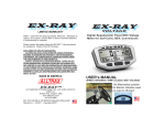
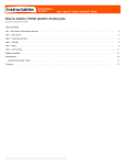
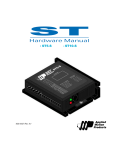
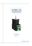
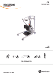
Operators Manual
Model:
AXE Series
Series Wound DC Electric Motor Controller
© 2005 ALLTRAX INC.
AllTrax inc
1111 Cheney Creek Rd
Grants Pass, OR 97527, USA
Phone: 541-476-3565
Fax: 541-476-3566
www.alltraxinc.com
PN: Doc100- 003-A_OP-AXE-Operators-Manaul.doc (Rev A)
Table of Contents
1.
AXE MOTOR CONTROL PRODUCT OVERVIEW ............................................................................... 3
2.
REQUIRED ACCESSORIES ..................................................................................................................... 4
2.1
2.2
2.3
2.4
3.
BATTERY CONTACTOR (SOLENOID OR RELAY)....................................................................................... 4
MAIN FUSE (PROVIDED WITH CONTROLLER).......................................................................................... 4
SAFETY DISCONNECT ............................................................................................................................ 5
DRIVE MOTORS .................................................................................................................................... 5
CONTROLLER INSTALLATION ............................................................................................................ 5
3.1
3.2
CONTACTOR COIL DIODE: ..................................................................................................................... 5
PRE-CHARGE RESISTOR:........................................................................................................................ 5
4.
LED STATUS INDICATOR....................................................................................................................... 6
5.
SOFTWARE USE AND CALIBRATION.................................................................................................. 7
6.
PROGRAMMING THE CONTROLLER: ................................................................................................ 8
6.1
CONTROL PANEL TAB ........................................................................................................................... 9
6.1.1
SWITCHES: .................................................................................................................................... 9
6.1.2
SETTINGS: ................................................................................................................................... 10
6.2
THROTTLE RESPONSE T AB .................................................................................................................. 11
6.2.1
Throttle Sensor Type...................................................................................................................... 11
6.3
MONITOR TAB .................................................................................................................................... 12
6.3.1
Monitor Section:............................................................................................................................ 12
6.3.2
Interval Section: ............................................................................................................................ 12
6.3.3
Gauges Section:............................................................................................................................. 13
7.
LIMITED WARRANTY........................................................................................................................... 14
Keep this manual
AllTrax Inc.
Doc100-003-A_OP-AXE-Operators-Manual
Page: 2 of 14
1.
AXE Motor Control Product Overview
Thank You for purchasing the Alltrax motor controller. We design and manufacture products for
a variety of electric vehicles and markets. This motor controller employs modern power
MOSFETs to provide extremely low “on” resistance, in both the main switch function and
freewheel diode.
Synchronous freewheel rectification permits extended high power operation
over similar sized controllers due to increased efficiency. A microprocessor
based control system monitors numerous functions, and a windows interface
allows the user to change numerous operating parameters and perform status
monitoring.
Replaces Curtis
1204 (6.5” long)
AllTrax Inc.
Doc100-003-A_OP-AXE-Operators-Manual
Replaces Curtis
1205 (8.5” long)
Page: 3 of 14
2. Required Accessories
These components are not supplied with the controller, except the main fuse. For your safety
and that of others, some basic precautionary measures must be employed when designing,
working on, and driving electric vehicles.
•
•
•
Use a contactor in the battery circuit, rated for the amperage and voltage of the system.
Use a fuse rated for the voltage and available fault current of the battery, such as the one
provided.
Safety interlocks must be employed to prevent enabling the controller while the vehicle is
unoccupied or charging.
Controllers have failure modes which can result in runaway (stuck throttle) conditions. This
controller has been designed to prevent and preclude as many of those from ever occurring as
possible. Please follow the Recommended Controller Wiring System document in this manual.
Failure to do so could result in damage to the controller, and serious injury or death to vehicle
occupants or bystanders
2.1 Battery Contactor (Solenoid or Relay)
The main battery contactor needs to be rated correctly in terms of amps and volts, in order to
safely carry the intended continuous battery current, and to interrupt the pack DC voltage. It’s
coil voltage should also be rated for the pack voltage.
2.2 Main Fuse (Provided with Controller)
• The main fuse needs to be sized to protect the wiring in
the drive system.
• Fuse DC voltage rating must be greater than the peak
battery voltage.
• Fuse current rating equal to or less than amperage
rating of controller.
Most high current fuses have very long tolerance (2 minutes or more) up to 50 - 100% overloads.
Thus a 300A fuse likely won’t open in a 500A vehicle application. Most Golf OEM vehicles
may not have a fuse and must be added with these performance controller upgrades. When carts
are equipped with large controllers, the wire gauge must be made larger. This in turn permits
higher fault currents, due to the reduced wiring resistance. Under these conditions, we strongly
recommend the addition of a fuse to prevent catastrophic battery failure or fire in the event of an
electrical system failure.
AllTrax Inc.
Doc100-003-A_OP-AXE-Operators-Manual
Page: 4 of 14
2.3 Safety Disconnect
The safety disconnect provides a way to disconnect the battery pack from the controller and
contactor. It may be a circuit breaker, a mechanical switch, or a large removable connector.
Make sure it is rated for the current capacity and DC Voltage of your system. Some
installations disconnect both the positive and negative leg of the battery pack. Most Golf type
vehicles do not have a battery disconnect.
2.4 Drive Motors
The motor controller is designed to operate with series wound brush commutated and permanent
magnet motors rated for operation from 12-72 VDC. Operation with compound motors is
possible. Contact Alltrax, Inc. for information on using compound motors.
3. Controller Installation
Choose a location outside the driver’s compartment to mount the controller. Any mounting
position is acceptable. It is recommended that you protect the controller from direct contact with
water, as the electrical connections can corrode. In high moisture environments, seal the
electrical connections with silicone or grease.
Mount the controller as close to the motor as is reasonably possible. Ideally, your motor leads
should be less than 4 feet long. Making a twisted pair out of the motor leads will reduce RF
emissions.
• Most car employ small (6AWG) battery interconnect wiring.
• For 400A controllers, a minimum of 4AWG wire should be used in light weight carts.
• 2AWG to 1/0 is appropriate for higher amperage controllers and heavier vehicles.
High current wiring to the motor controller should use 5/16” mounting hole ring terminals of
tinned copper. Bolt them to the controller using 5/16” hardware.
3.1 Contactor Coil Diode:
CAUTION: A Diode (1A, 100V) MUST BE USED across the solenoid/contactor coil (and any
other relays that may be installed to control lights or accessories). The Cathode or banded end
faces the positive terminal. These diodes are required to prevent the speed sensor from
producing erroneous signals.
3.2 Pre-charge Resistor:
The controller has a fair amount of DC filter capacitance. When the contactor closes to apply
power to the controller, the capacitors can arc the contactor. The pre-charge resistor wil apply a
low current to the capacitors to prevent any arcing and keep the capacitors at bus voltages. It
also acts as a discharge snubber that helps dissipate the arc when the contactor disengages. (see
schematics for proper value).
AllTrax Inc.
Doc100-003-A_OP-AXE-Operators-Manual
Page: 5 of 14
4. LED Status Indicator
The AXE controller has a bicolor front panel LED. This LED displays a variety of
information each time the controller is powered up, by series of blinks. Count the
number of green blinks to identify the type of throttle the controller is configured for.
After the blink code indicating throttle type, the LED will stay green if there are no errors.
LED
LED Blink Codes:
At power up the number of green blinks indicates the configured throttle type:
1 Green = 0-5k
2 Green = 5k-0
3 Green = 0-5V
4 Green = EZ-GO inductive (ITS)
5 Green = Yamaha 0-1K
6 Green = Taylor-Dunn 6-10.5V
7 Green = CLUBCAR 5K-0, 3-wire
Normal display status:
Solid Green: Controller ready to run
Solid Red:
Controller in programming mode
Solid Yellow: Controller throttle is wide open, controller is supplying max
output, and is not in current limit.
Error code display:
Number of RED blinks indicates any error conditions that might exist.
1 Red = Throttle Position Sensor Over Range. Check for open wires.
2 Red = Under Temperature. Controller below -25C.
3 Red = HPD. Throttle hasn't gone to zero during this power on cycle.
4 Red = Over Temperature. Controller over 95C.
5 Red = unused for series controllers.
6 Red = Battery Under Voltage detected. Battery V < undervoltage slider.
7 Red = Battery Over Voltage detected. Battery V > overvoltage slider.
Errors are self clearing when the fault is corrected.
AllTrax Inc.
Doc100-003-A_OP-AXE-Operators-Manual
Page: 6 of 14
5. Software Use and Calibration
The Alltrax Motor controllers utilize a computer program to provide the motor drive functions, motor field
current mapping, and a myriad of other customizable features such as speed, current, throttles, etc.
A majority of the Alltrax motor controllers also have the ability to be re-programmed with upgraded
software. In most cases, it is not necessary to upgrade the unit’s software for stock or aftermarket
replacements unless a specific revision is needed for a particular application.
See Controller Pro Operators manual for more detailed operation.
Software:
•
Controller Pro Software (see www.alltraxinc.com and download
http://www.alltraxinc.com/old/Software/WEBControllerPRO.zip
Through may customer service calls we have found 90% of the problems with communicating
between the computer and the motor controller was the inability of the windows software to
assign communications ports. We found using a USB to Serial Adapter eliminated any
communications port issues with success to connect properly the first time.
Recommended serial to USB adapter:
•
Cables to Go, Port Authority™ 2 USB to Serial Adapter. www.cablestogo.com (shown
above)
•
Radio Shack, 6 Ft. (1.8m) USB-to-Serial Port Cable, Model: 26-183, Catalog #: 26-183
(Shown below)
WARNING: Disconnect all battery charging sources
while programming your Axe Controller.
The controllers RS-232 serial port is referenced to the Bbattery connection.
Beware any possible ground loop faults between your
computer and the controller which could damage both the
Axe Controller and PC, plus the person doing the work!
AllTrax Inc.
Doc100-003-A_OP-AXE-Operators-Manual
Page: 7 of 14
6. Programming the Controller:
The AXE controller must be powered up before the Controller Pro program will have any effect.
Any programming changes done in the vehicle should be performed with the vehicle safely
disabled. Either put the drive wheels on jack stands, or position the vehicle where it is safe to
drive while altering the controller. For bench programming prior to installation, two 9V batteries
in series may used to power up the controller. Connect battery negative to the B- bus bar, battery
positive to pin 1, (spade tab closest to the LED).
When the AXE is connected to the PC, and both units are energized, launch ControllerPro.EXE.
If you see an error “Motor Controller Not Responding”, it means the Controller and PC are not
communicating. Hit “OK”, and the Controller Pro will display a window. Recheck the cable
connections then close and re-open Controller Pro. Controller Pro automatically determines
which com port the controller is connected to. If, after going through this the controller will still
not establish communications with the PC, try turning the AXE controller off, then back on.
Observe the LED on the AXE went out, then came back on, indicating you cycled the power.
Restart the Controller Pro program.
When communications is established
with the controller, a Model number
(like AXE4844) should be displayed
in the Control Panel pane, along with
the current configuration of the AXE
motor controller.
The top row of functions is Settings, Tools and Help. The normal parameters of the “settings,
program…” portion of this program will enable the software to work on most PCs. However, in
some very electrically noisy systems, it may be necessary to increase the write delay above 20mS
or increase the number of retries, such that communications errors are eliminated.
Tools: This function of the program allows you to modify the main executable program that
operates the controller (to modify the behavior of a standard controller by adding special features
like increased throttle response speeds for go-karts) or extract an error log from the controller for
diagnostics.
Upgrade: This function loads a new executable program into the controller.
Reset: Restarts the controller without cycling the power.
Write error log: This function downloads the last 32 (if any) errors that the controller has logged
into it’s EEPROM memory. These are things like HPD, hi/low battery voltage, and
over/under temperature.
AllTrax Inc.
Doc100-003-A_OP-AXE-Operators-Manual
Page: 8 of 14
6.1 Control Panel Tab
This tab allows you to alter the operating characteristics of the AXE. Changes made on this pane
only take effect after the “SET’ button is pressed. “Refresh” will read the current settings from
the controller. After any changes have been “SET”, always click “REFRESH” to confirm the
changes were accepted by the controller. Note: HPD and Plug Brake switches only take effect at
power up, the power to the controller will have to be cycled before these two controls have any
effect on the machines operation. The “DEFAULTS” button will restore the factory default
values of the sliders, note that “SET” must still be pressed for these parameters to be stored in
the AXE controller.
6.1.1 SWITCHES:
High Pedal Disable
Checking this box enables HPD, which will prevent the controller from providing output
power in the event the throttle is applied when the controller is powered on. When this
box is clear, the controller will start up and provide output power, when KSI energized,
regardless of initial throttle position.
Plug Brake
Checking this box enable plug braking on those controllers equipped with an A2 bus bar
terminal. Plug braking on AXE controllers is proportional to throttle position, reaching
full braking force at about 25% of throttle travel. Deselecting this box disable plug
braking, the unit will apply normal power to motor if direction is reversed. (vehicle may
jerk or spin tires if motor direction is reversed while in motion)
Turbo
A feature that allows DCX controllers (not AXE controllers) to go faster if under light
load and 100% throttle.
½ Speed Reverse
Limits speed of golf car to 50% of throttle setting when pack + is applied to this pin.
AllTrax Inc.
Doc100-003-A_OP-AXE-Operators-Manual
Page: 9 of 14
6.1.2 SETTINGS:
Maximum Output Current
This slider adjusts the maximum output current that the controller can provide to the
motor. Output current is adjusted as a percent of the maximum rating of the controller.
For example, an AXE4844 will provide a maximum of 400A to the motor when this
slider is set to 100%. A 75% setting on Maximum Output Current will limit the
controller to 300A, 50% will limit the max output current to 200A and so forth.
Under Voltage
This slider sets the under voltage shutdown of the controller, in units of 1/10ths Volt.
Generally speaking, it is undesirable to pull the terminal voltage of a 6V lead-acid
battery below 4.0V, for example 24V on a 36V system.
Over Voltage
This slider sets the maximum operating voltage of the controller. If the voltage present
across the B- to B+ bus bars exceeds this setting, the controller will not produce output,
given that DC voltage is below the absolute ratings of the controller.
Throttle Up Rate
This slider adjusts the rate at which the controller increases it’s output current in response
to an increase in throttle position. 1 is the slowest, 15 the fastest.
Throttle Down Rate
This slider adjusts the rate at which the controller reduces it’s output current in response
to a decrease in throttle position. 0 is the slowest, 15 the fastest. It is recommended that
this parameter typically be set to twice the value of the throttle up rate, when throttle up
rate is less than 7. Lower values of Throttle Down Rate can result in the vehicle feeling
as if their were a large flywheel connected to the motor.
Brake Current
On those models equipped with a plug brake (suffix “P” in the model number), this slider
adjusts the amount of brake current as a percent of maximum available brake current.
Refer to AXE specifications for maximum available brake current depending on the
model of controller.
Top Speed
Top speed of the controller can be limited from 100% down to 50%. This is a helpful
tool for elderly or handicapped drivers.
AllTrax Inc.
Doc100-003-A_OP-AXE-Operators-Manual
Page: 10 of 14
6.2 Throttle Response Tab
This pane allows you to select which type of throttle position sensor the controller is working
with and what type of throttle response profile to use with the sensor. Changes to throttle sensor
type check boxes must be SET to take effect, and then only after the power to the Axe has been
cycled do they actually change the sensor type.
6.2.1 Throttle Sensor Type
0-1K Ohm (Yamaha type):
When selected, the controller interprets 0-80 ohms = throttle off, 1K ohms = full on.
0-5K Ohm:
When selected, the controller interprets 0 ohms = full off throttle, 5K ohms equals full on.
Specifically, Zero ohms to 180 ohms = full off, 4.7K to 5K = full on.
5K-0 Ohm:
When selected, the controller interprets 5K ohms = full off throttle, 0 ohms equals full on.
Specifically, Zero ohms to 250 ohms = full on, 4.3K to 5K = full off.
0-5V:
This selects a voltage controlled type of throttle input. 0V = full off output from
controller, 5V = full on. Actual operating range is 0.15 – 4.90V.
6-10.5V (Taylor-Dunn type):
This throttle sensor is voltage controlled. 0-6V = throttle off, 10.5V = full on.
5K-0, 3 wire (Club Car type):
This throttle sensor employs a 3 wire potentiometer, or the V-Glide throttle position unit.
5K = throttle off, <200 ohms = full throttle.
EZ-GO ITS:
This throttle sensor type is compatible with the EZ-Go type of inductive throttle position
sensor (ITS).
AllTrax Inc.
Doc100-003-A_OP-AXE-Operators-Manual
Page: 11 of 14
Throttle Sensor Type Continued:
Pump:
This throttle setting allows the AXE controller to power pumps used on fork lifts and
other hydraulic applications where pumps are used. The controller turns on 100% output
when the Pin 1 spade lug sees pack voltage. The ramp-up and ramp-down rate is still
controlled by the two sliders on the Control Panel.
6.3 Monitor Tab
This screen is the status monitor of the Axe controller, it gives you the ability to measure and
record numerous operating parameters of the Axe motor controller and the vehicle in which it is
installed. When used with a Notebook computer, both real-time data display and data logging
may be performed while the vehicle is in use. This gives the vehicle designer significant insight
to the interaction of the motor controller with other system components. Log files may be used
for problem analysis and diagnostics. You can email the log file to Alltraxinc.com for a detailed
analysis by our applications engineers.
6.3.1 Monitor Section:
Start/Stop: This starts and stops the data measurement process
Select All: Checks all the gauges
Clear All: Deselects all the gauges
Log to File:
This checkbox will log all of the selected gauge values to a file when selected. The file is
in a comma delimited format (CSV) which can be imported into a spreadsheet program
like Excel and viewed. The resulting file will be placed into a subdirectory called “Logs”
in the same directory as the program Motorcontrol.exe
6.3.2 Interval Section:
This checkbox selects the update rate, or frequency of data collection. For real time display,
select continuous. When used in conjunction with “Log to File”, a slower update rate may be
more desirable to reduce the amount of raw data being gathered.
AllTrax Inc.
Doc100-003-A_OP-AXE-Operators-Manual
Page: 12 of 14
6.3.3 Gauges Section:
These are the motor controller parameters which are to be monitored. Checking an adjacent box
enables that measurement. Clicking “Refresh” will perform a one-time update to the gauges
which are selected. It is generally recommended that you select all the gauges, as this will
provide the most insight into the operation of the controller.
Throttle Position:
This gauge displays the % modulation of the controllers PWM output. For example 50%
would be ½ throttle. The displayed parameter is the actual throttle position, limited by
the fact that the controller could be in current limit. If the controllers output current
reaches the maximum rating, the throttle position won’t advance any further, regardless if
the throttle is full on.
Controller Temperature:
This is the internal temperature of the controller, in Celsius. Accuracy: +/- 5%.
Battery Voltage:
This is the voltage present across the B+ and B- bus bars of the controller. Exception:
Club Car compatible models. This is the voltage present across the KSI input to B- bus
bar of the AXE controller. Accuracy: +/- 5%
Output Current:
This is the measured output or motor current of the controller, accuracy +/-10%
Battery Current:
This is the calculated input or battery current to the controller. It is calculated as: Battery
current = motor current x throttle position %. It is accurate, given that motor current is
continuous (which it generally is with any series motor), not discontinuous. Accuracy:
+/- 10%
Error Flags:
This register should display as 0x00 during normal operation. Any value greater than
zero is an error, and the controller will not provide any output power.
At the moment, this data is in hexadecimal format. If the two right-most hex digits (those
to the right of 0x) are converted to an 8 bit binary value, the individual bit positions (with
bit 0 being the right-most digit) when set represent the following error flags:
Bit 0 set =
Bit 1 set =
Bit 2 set =
Bit 3 set =
Bit 4 set =
Bit 5 set =
Bit 6 set =
Bit 7 set =
AllTrax Inc.
Throttle Position Sensor Over Range
Under Temperature. Controller below -25C
HPD. Throttle hasn’t gone to zero during this power on cycle.
Over Temperature. Controller over 95C
unused
Battery Under Voltage detected. Battery V < under voltage slider
Battery Over Voltage detected. Battery V > over voltage slider
Controller in boot sequence. Occurs within 25mS of power up.
Doc100-003-A_OP-AXE-Operators-Manual
Page: 13 of 14
7. LIMITED WARRANTY
Alltrax, Inc. warrants every product it sells to be free from defects in materials or workmanship
for a period of 2 years from the date of manufacture. This warranty does not apply to defects
due directly or indirectly to misuse, abuse, negligence, accidents, repairs or alterations. We shall
in no event be liable for death, injuries to persons or property or for incidental, contingent or
consequential damages arising through the use of our products. Alltrax, Inc. specifically
disclaims the implied warranties of merchantability and fitness for a particular purpose; however
some areas do not allow limitations on how long an implied warranty lasts, so the preceding
exclusion may not apply to you. This is Alltrax, Inc. sole written warranty; no other warranty is
expressed or implied.
In the event you should need warranty repair, Please see the Return Procedure below. Alltrax
reserves the right to repair or replace merchandise at its option. Alltrax reserves the right to
make changes to any of its products or specifications without notice.
Return Procedure:
Call Alltrax, Inc. at (541) 476-3565
Fax us at (541) 476-3566
Or visit us on the Web at www.alltraxinc.com
Explain the nature of the problem to our service personnel and we will provide you with
return directions You pay shipping to us, we pay the return shipping. Package the
device securely in original shipping box if at all possible; we are not responsible for
damage in shipping.
AllTrax Inc.
Doc100-003-A_OP-AXE-Operators-Manual
Page: 14 of 14