1
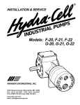
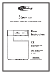
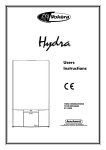
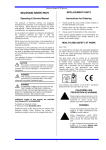
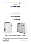
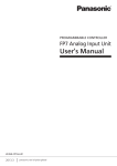
OPERATOR’S MANUAL
INCLUDES OPERATION, MAINTENANCE AND TROUBLESHOOTING GUIDES
UV-R01
LAST MODIFIED 21/03/2004
v1.0
UV INK PUMP & RAM SYSTEM
AIR OPERATED VARIABLE MIX AND DISPENSE SYSTEM
PLEASE READ THIS MANUAL CAREFULLY BEFORE OPERATING,
ADJUSTING OR SERVICING THIS EQUIPMENT
It is the responsibility of the employer to place this information in the hands of the operator. Keep for future reference.
GENERAL SYSTEM DATA
Ram Type
Ram System Materials
Pump Type
Pump Model
Pump Materials
Max. Air Inlet Pres. (pump)
Min. Air Inlet Pres. (pump)
Max. inlet Pressure (ram)
Variable Flow Rate
Max. Temp. Limits
General Dimensions
Noise Levels @ 70psi
1:1 ratio Air-operated Single
Post Piston Lift & Ram. Welded
and bolted construction, Powder
Coated finish.
Steel / Aluminium.
Non-metallic Air-operated
Double Diaphragm.
ARO 1:1 ratio Pump.
UV Stabilised Polypropylene.
120 psig (8.3 bar)
20 psig (1.4 bar)
10 psig (0.69 bar)
To individuals requirement.
35º - 150º F (2º - 66º C)
100” x 39⅜” x 29½”
(2540 x 1000 x 750mm).
64.5 db(A) * +
* The pump sound pressure levels published here have been updated to an Equivalent Continuous Sound
Level (Laeq) to meet the intent of ANSI S1.13-1971, CAGI-PNEUROPS5.1 using four microphones
+
Tested with 93110 Muffler installed.
GENERAL DESCRIPTION
The UV Ink Pump & Ram System allows for the safe transfer
and accurate dispensing of ultra-violet and light sensitive fluid
products.
The system is a total pneumatic package utilising a diaphragm
pump for the transfer of ink. Ink is dispensed via a spring return
valve within a closed loop dispensing circuit.
The system is integrated into a floor plate design package (free
standing) and is suitable for all environments. The system has
been designed to work with 205 litre drums, of any design.
Easy to install, easy to operate, maintenance free, and full
global support available.
AIR PUMPING ENGINEERING SERVICES LIMITED
P.O. BOX 239 • LONDON • E6 3SG • U.K.
TEL: +44 (0) 20 8470 8721 • FAX: +44 (0) 20 8470 4617
PRINTED THE IN U.K. © 2003
UV-R01
PUMP OPERATING & SAFETY PRECAUTIONS
PLEASE READ AND FOLLOW THIS INFORMATION TO AVOID PERSONAL INJURY AND PROPERTY DAMAGE
WARNING!
Excessive Air Pressure can cause personal injury, pump damage or property damage.
Disconnect air supply line and relieve pressure
from the system by opening dispensing valve
or carefully removing outlet hose or piping.
WARNING!
DO NOT exceed the maximum inlet air pressure
as stated.
STATIC SPARK. Can cause explosion resulting
in severe injury or death. Ground pump and
system.
The pumping system and object being sprayed
must be grounded when it is pumping, flushing,
re-circulating or spraying flammable materials
such as paints, solvents, lacquers, etc. or used
in a location where the surrounding atmosphere
is conductive to spontaneous combustion.
Ground the dispensing valve or device, containers, hoses and any object to which material is
being pumped.
Secure pump, connections and all contact
points to avoid vibration and generation of contact or static spark.
After grounding periodically verify continuity of
electrical path to ground. Test using an Ohmmeter, should show 100 ohms or less.
Use hoses incorporating a static wire.
HAZARDOUS MATERIALS. Do not attempt to
return a pump to the factory or service centre
that contains hazardous material. Safe handling practices must comply with local and national laws and safety code requirements.
Obtain Material Safety Datasheets on all materials from the supplier for proper handling instructions.
CAUTION!
Chemical compatibility may change with temperature and concentration.
Maximum temperatures are based on mechanical stress only.
Certain chemicals will significantly reduce
maximum safe operating temperature.
Be certain all operators of this equipment have
been trained for safe working practices, understand it’s limitations, and wear safety goggles /
equipment where required.
CAUTION!
Use proper ventilation and keep containers
closed when not in use.
WARNING!
Pump exhaust may contain contaminants. Can
cause severe injury. Pipe exhaust away from
work area and personnel.
Prevent unnecessary damage to the pump. Do
not allow the pump to operate when out of material for long periods of time.,
Disconnect air line from pump when system
sits idle for long periods of time.
In the event of a diaphragm rupture, material
can be forced out of the air exhaust muffler.
Do not service or clean pump, hoses or dispensing valve while the system is pressurised.
WARNING!
Page 2 of 8
Hazards or unsafe practises
which could result in severe
personal injury, death or
substantial property damage
CAUTION!
Hazards or unsafe practises
which could result in minor
personal injury, product or
property damage
UV-R01
RAM OPERATING & SAFETY PRECAUTIONS
PLEASE READ AND FOLLOW THIS INFORMATION TO AVOID PERSONAL INJURY AND PROPERTY DAMAGE
WARNING!
WARNING!
ANCHOR THE LIFT BASE SECURLY ON A FLAT
SURFACE. AN IMPROPERLY SECURED LIFT IS
UNSAFE. Do not attempt to use the lift until all
possible measures have been taken to insure
that the lift has been properly installed and the
base is securely fastened.
STAND CLEAR. When raising or lowering the
lift, it is good safety practice to stay clear of the
raised lift and operate it from a safe position.
PREVENT ELECTRIC SHOCK. Be certain the
area above the lift is clear of electrical fixtures,
devices and wiring. Examine the working area
and take necessary action to assure adequate
clearance for the lift and pump assembly to raise
the fullest limit and function properly.
WARNING!
PINCH HAZARD. Follower can descend quickly,
causing injury. Keep hands clear when aligning
with container. Do not rotate the pump to the next
drum by grasping the follower plate. In the raising
and lowering function, the speed is controlled by
Exhaust Speed Controls. In a situation where the
lift could get hung up or the descent is restricted
temporarily, the lift could in some situations drop
rapidly and be hazardous. If the follower plate does
not enter the drum properly; DO NOT ATTEMPT
TO REPOSITION IT WITH YOUR HANDS; raise
the lift and re-start.
WARNING!
UV-R01
Hazards or unsafe practises
which could result in severe
personal injury, death or
substantial property damage
HAZARDOUS PRESSURE. Do not exceed maximum air pressure of 150 psi (10.3 bar). Operating lift at higher pressure may cause lift damage
and / or personal injury and / or property damage.
Do not service or clean pump, hoses or dispensing
valve while system is pressurised.
Know the pressure limitations of the drum and
regulate the air pressure within safe limit when supplying air to follower plate.
CAUTION!
Be certain all operators of this equipment have
been trained for safe working practices, understand it’s limitations, and wear their safety goggles / equipment as required.
CAUTION!
Hazards or unsafe practises
which could result in minor
personal injury, product or
property damage
Page 3 of 8
OPERATIONAL AREA
DIMENSIONS SHOWN ARE FOR GUIDANCE ONLY AND ARE DISPLAYED IN MILIMETRES AND (INCHES)
When installing the system, please ensure an adequate operating area is maintained. Due to the nature of the system,
the unit can be fully operational from any one of the three positions below. The mounting plate of the system is designed to allow the safe operation of the unit from all positions, but this must be kept clear to the edge of the plate for
correct access and use.
Please refer to the diagram below when siting or installing the unit.
750 mm (29 ½”)
1000 mm (39 ⅜”)
1423 mm (56”)
diameter
Operating Area
Page 4 of 8
813 mm (32”)
diameter
UV-R01
OPERATING INSTRUCTIONS
PLEASE READ AND FOLLOW THIS INFORMATION TO AVOID PERSONAL INJURY AND PROPERTY DAMAGE
OPERATING INSTRUCTIONS / INITIAL SETUP
PROCEDURE
WARNING: BE CERTAIN HEAD, HANDS AND
ARMS ARE CLEAR OF ASCENDING AND DESCENDING LIFT. Refer to OPERATING &
SAFETY PRECAUTIONS on page 3.
TO RAISE LIFT (NORMAL OPERATION)
1.
2.
3.
4.
If a vent plug is part of your Follower Plate
setup, remove the Follower Plate vent plug to
prevent a build up of vacuum when raising
the follower plate.
If there is no vent plug, Adjust the Air Valve
pressure up to approximately 8 psi/g. DO
NOT OVERPRESSURISE THE DRUM to
avoid damage.
Shift the Control Valve Lever to the UP position.
Raise the lift high enough to clear the height
of the drum. Stop the lift upward travel by
moving the Control Valve Lever to the NEUTRAL (centre) position.
TO CHANGE DRUMS:
NOTE: The raised lift control valve should be in the
NEUTRAL position.
1.
Place a new drum into position or rotate the
lift and pump to the next drum position.
TO LOWER LIFT:
EXHAUST SPEED CONTROLS: These meter the
flow of air from the valve exhaust ports. The rate of
rise or descent of the lift may be increased or decreased by adjusting the screw. The adjusted position can then be locked in place by a lock nut.
TO RAISE LIFT (FIRST TIME)
1.
2.
3.
4.
Take note of the pump / drum clearance
above. If additional clearance is needed to
clear the drum, lower the lift, loosen the Vertical Arm (15) bolts, turn the Vertical Arm Adjustment Nut and re-tighten the (15) bolts.
Connect the air supply (150 psi MAX) to the
air inlet.
Shift the Control Valve Lever to the “up” position. Be certain the lift is clear of any objects
above. Also refer to OPERATING & SAFETY
INSTRUCTIONS found on page 3.
Raise the lift high enough to clear the height
of the drum. Stop the lift upward travel by
moving the Control Valve Lever to the NEUTRAL (centre) position.
UV-R01
WARNING!
STAND CLEAR: When raising or lowering the
lift. Read the warning on page 2.
PINCH HAZARD: Follower can descend quickly
causing injury. Keep hands clear when aligning
with container. Read the warning on page 2.
NOTE: When follower plate lowers into drum be
certain the Follower Plate vent plug has been removed (if applicable) so that the air trapped between the follower and the material is allowed to
escape.
NOTE: The lift may hesitate momentarily before
starting downward, the air pressure inside the post
air chamber must decrease before it will begin to
descend.
1.
2.
Shift the Control Valve Lever to the DOWN
position and proceed to lower the pump.
Replace the vent plug (if applicable).
Page 5 of 8
PARTS LIST FOR UV-R01
PLEASE REFER TO THESE DIAGRAMS FOR TROUBLESHOOTING AND SPARES PROCUREMENT
Item
Description
(Qty) Part No.
1
Screw
(8)
Y6-65-C
2
Stop nut, elastic
(8)
Y108-3-Z
3
Socket head screw
(4)
Y99-61
4
Lock washer
(4)
Y14-616
5
Nipple
(1)
Y44-12-C
6
Socket head screw
(1)
Y99-83
7
Bracket assy.
(1)
67071-4
8
Inner tube assy.
(1)
67071-8
9
Rod assy.
(1)
67071-7
10
Nut
(1)
Y12-112-C
11
Air line tubing
(1)
44632-( )
12
Cylinder
(1)
AP1009370
13
Outer tube assy.
(1)
67071-6
14
Vertical adj. bracket assy.
(1)
67071-3
15
Bolt
(2)
------
16
Face bushing
(2)
93948-29
17
Air line fitting
(2)
93948-30
18
Air line tubing
(1)
44632-( )
19
Socket head screw
(6)
Y99-82
20
Clevis pin
(1)
5814
21
Clip retainer
(2)
Y180-43
22
Mounting plate
(1)
67071-5
23
Straight A’line fitting
(4)
59688-4
24
Directional decal
(1)
92449
25
Exhaust speed control
(2)
20313-2
26
Air line guage
(1)
29850
27
Air line regulator
(1)
127122-000
28
“E” series 4-way valve
(1)
E512LM
29
Air line tubing
(2)
44632-( )
30
90º Legris fitting
(2)
59745-154
31
Screw
(3)
Y6-46-C
32
Decal, pinch warning
(1)
93922
Repair kit available for Valve
116722
Repair kit available for Cylinder
RK2425
Bulk tubing
Page 6 of 8
59690-104
UV-R01
PARTS LIST FOR UV-R01 cont.
PLEASE REFER TO THESE DIAGRAMS FOR TROUBLESHOOTING AND SPARES PROCUREMENT
Item
Description
(Qty) Part No.
Item Description
(Qty)
Part No.
1
Follower seal
(1)
91060
8
Follower plate welding assy.
(1)
66247
2
Backup washer
(1)
92035
9
Cap screw
(6)
Y6-54-C
3
Follower Ring
(4)
90725
10
Gasket
(1)
91742
4
Pipe plug
(1)
Y17-13-C
11
Cap screw
(20)
Y6-43-C
5
Adaptor
(1)
91751
12
Stud
(2)
91263
6
Nut
(6)
Y12-5-C
13
Gasket
(1)
90552
7
Nut
(20)
Y12-4-C
14
Screw
(4)
Y99-63-C
UV-R01
Page 7 of 8
PUMP DIMENSIONAL DATA
DIMENSIONS SHOWN ARE FOR GUIDANCE ONLY AND ARE DISPLAYED IN MILIMETRES AND (INCHES)
TROUBLESHOOTING
Ram system will not lift
Check air supply.
·
Check control valve connections
·
Ensure you have adequate clearance for the ram
·
system to lift.
If you have a vent plug in your Follower Plate, re·
move or loosen it and retry
If you do not have a vent plug on your Follower
·
Plate, adjust the air valve pressure, located close to
the Control Valve Lever, to approx 8 psi/g (0.55
bar) and retry
Low
·
·
·
·
·
·
Product discharged from exhaust outlet
Check for diaphragm rupture.
·
Check tightness of diaphragm nut.
·
output volume, erratic flow or no flow
Check air supply.
Check for plugged outlet hose.
Check for kinked (restrictive) outlet material hose.
Check for pump cavitation - suction pipe should be
sized at least as large as the inlet thread diameter
of the pump for proper flow if high viscosity fluids
are being pumped. Suction hose must be noncollapsing type, capable of pulling a high vacuum.
Check all joints on the inlet manifolds and suction
connections. These must be air tight.
Inspect the pump for solid objects logged in the diaphragm chamber or valve seat area.
If any of the above measures fail to lift your ram system or get you pumping again, please do not hesitate
to contact Air Pumping Engineering Services for further information or to arrange a service visit
Air bubbles in product discharge
Check connections of suction plumbing.
·
Check “O” rings between intake manifold and fluid
·
caps.
Check tightness of diaphragm nut.
·
Page 8 of 8
UV-R01