1
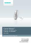
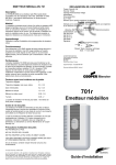
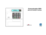
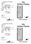
USER GUIDE MRX - 6600 MINI-RECEIVER Leading the way in security Contents 1. Introduction .............................................................................................. 3 Controls and Display ....................................................................................................... 4 Handset/Headset ............................................................................................................ 4 Switching Power On .............................................................................................................. 5 2. Using the Receiver ................................................................................... 6 Voice Calls ............................................................................................................................. 6 Data Calls ............................................................................................................................ 10 Reading and Printing the Log ............................................................................................. 12 Showing a User Name in the Log ....................................................................................... 12 3. Adjusting the Console ............................................................................. 13 Changing The Speech Message .................................................................................. Setting the Internal Clock/Calendar ............................................................................. Changing the Key Click Volume ................................................................................... To make the key clicks louder: ............................................................................... To make the key clicks quieter: .............................................................................. To turn the key clicks off or on: .............................................................................. Turning the Backlight On/Off ............................................................................................... Changing the Language Used on the Display .................................................................... Testing the Lights ................................................................................................................ 13 14 14 14 14 14 15 15 15 4. Installing or Replacing Batteries ............................................................. 16 Checking the Battery and Mains ......................................................................................... 16 Replacing the Battery .......................................................................................................... 16 5. Quick Reference Chart ........................................................................... 17 1. Introduction The Scantronic Mini Receiver is designed for use by one person answering incoming calls at a small monitoring centre. Example applications include sheltered housing, retirement homes, hospices, neighbourhood watch coordinators and small alarm companies. Mains connection PC (optional) Telephone lines Logging printer (optional) Handset Minireceiver Figure 1. Mini Receiver and Optional Attachments The Mini Receiver can be connected to two telephone lines, answering calls on either of them. The operator can place an established call on hold to deal with incoming calls on the other line. The Mini Receiver is fitted with an internal microphone and loudspeaker, but also provides sockets for a handset or headset. A volume control can be used to alter the volume of the loudspeaker (but not the sensitivity of the microphone). If the calling device is fitted with a separate microphone and speaker then the Mini Receiver can activate the remote microphone to allow you to listen, or the remote loudspeaker to allow you to speak. The Mini Receiver has two programmable outputs that can be connected to auxiliary devices. The outputs can be used, for example, to signal an incoming call. The Mini Receiver normally runs off mains AC power, but holds internal backup batteries in case of mains failure. 496464 3 1. Introduction This product is manufactured to meet all European Economic Area telecommunication networks requirements. Controls and Status Lights a 2 4 3 1 7 ¯ ¬ÿ® Mains power. Glows steadily when mains power is on. Flashes when mains power is absent. Note that it may take several seconds for the light to start flashing after a mains failure. Battery power. Flashes rapidly when the battery is absent or too low to operate unit. Flashes slowly when battery needs changing. Telephone line status. Flashes rapidly when the system detects ringing. Blinks slowly when there is a telephone line fault. Cancel. Flashes when the system is answering a data call. Press to acknowledge receiving a data call. Accept. Flashes when a voice call is on hold. Press to accept a voice call. Glows steadily while the line is active. Shutdown (red). Use this key to end a voice call. Glows steadily when you can shutdown a call. Note that you must hold the key down for at least three seconds. Talk/Listen. Press to listen, press again to talk. Note that this key does not work if the calling device has no microphone or loudspeaker. The light above the key glows when the microphone on the console is live. The light is off when you are listening to the calling device. Increase/decrease contrast on display. Step backwards/forwards through the log. Handset/Headset If you wish to use a handset or headset instead of the internal microphone and loudspeaker then plug in the hand/head set at the side of the unit, as shown in Figure 2. Handset ON (Loudspeaker OFF) Loudspeaker ON (Handset OFF) Handset/ Headset socket Volume control Figure 2. Handset or Headset Connection. 4 496464 1. Introduction To make the handset/headset operate slide the switch shown in Figure 2 toward the front of the unit. Note that with the switch in this position the internal microphone and loudspeaker are disabled. To control sidetone levels turn the control on the base of the unit in the direction shown in Figure 3. Sidetone louder Sidetone quieter Figure 3. Sidetone Control Switching Power On Plug the unit into the mains supply. Turn the unit on by pushing the slider switch at the rear away from the mains cable. 1 2 1 2 TC 1 O/P 2 0V +V 1 2 250V 160mA 1 0 110mA 250V~50Hz Power Switch ON OFF Figure 4. Power Switch The display shows the current software and date, for example: MRX A1.00 B1.00 01 Jan 2000 00:00:01 Note that you can reset the unit at any time by pressing Cancel and Shutdown ( 3 and ) together. 496464 5 2. Using the Receiver The receiver can deal with two types of calls: voice calls and data calls. The display shows the status of the telephone lines and the progress of incoming calls. Voice Calls Voice calls are started by a device that has a microphone and loudspeaker that the user can talk through. These devices are often special telephones that can be triggered by radio pendants. START THE ALARM F I R E POLICE 999 AMBULANCE OPERATOR 100 HOMELINK A caller triggers an alarm, for example by pressing a radio pendant. RINGING F I R E POLICE 999 AMBULANCE OPERATOR 100 HOMELINK 1 The alarm device rings the receiver. On the receiver the 4 light flashes to show that a call is arriving on a line, in this case line 1. 6 496464 2. Using the Receiver IDENTIFICATION 10110101 2 1 1001 F I R E POLICE 999 AMBULANCE OPERATOR 100 HOMELINK The alarm device and the receiver swap digital identification numbers. At this point the alarm device tells the receiver that this is a voice call. While this is happening the 3 light flashes on the console. RECORDED ANNOUNCEMENT "Hello, please wait for an operator..." 2 1 F I R E POLICE 999 AMBULANCE OPERATOR 100 HOMELINK Once the receiver has identified the alarm device, and discovered that this is a voice call, the system plays any recorded message to the alarm device and puts the call on hold. At the same time the 1 light flashes to show that someone wishes to talk to you. 496464 7 2. Using the Receiver ACCEPT THE CALL 2 1 2 Press 1 (accept) to take the incoming call off hold. The 1 light now glows steadily to show that you are dealing with that call, and the light by the red key glows to show that you can shutdown the call. Notice that the 7 light is off. This means that you are listening to the call. LISTEN TO THE CALLER 2 1 F I R E POLICE 999 AMBULANCE OPERATOR 100 HOMELINK While the 7 light is off you can hear the caller. 8 496464 2. Using the Receiver PRESS TO TALK 2 1 Press 7 to talk to the caller. Notice that the 7 light glows while your microphone is live. TALK TO THE CALLER 2 1 F I R E POLICE 999 AMBULANCE OPERATOR 100 HOMELINK While the 7 light glows you can talk to the caller. END THE CALL 2 1 Press the red key for three seconds to finish the call and release the line ready for the next call. 496464 9 2. Using the Receiver Data Calls A data call does not involve any speech. Data calls are often used by things such as fire detectors, or inactivity monitors. START THE ALARM F I R E POLICE 999 AMBULANCE OPERATOR 100 HOMELINK Some device, for example a mains failure, starts an alarm. RINGING F I R E POLICE 999 AMBULANCE OPERATOR 100 HOMELINK 1 The alarm device rings the receiver. On the receiver the 4 light flashes to show that a call is arriving on a line, in this case line 1. 10 496464 2. Using the Receiver IDENTIFICATION 10110101 2 1 1001 F I R E POLICE 999 AMBULANCE OPERATOR 100 HOMELINK The alarm device and the receiver swap digital identification numbers. At this point the alarm device tells the receiver that this is a data only call. While this is happening the 3 light flashes on the console. DISPLAY SHOWS CAUSE OF ALARM <LI> 22:04:02 220022 55515555,7 Line 1 (Please ACK) 03 Jan 2000 22:04:05 The top line of the display shows the data sent by the alarm device. (Example shows display with mnemonics off.) END THE CALL 2 1 Once you have noted the cause of the alarm, press 3 to cancel the alarm and free the line for the next call. 496464 11 2. Using the Receiver Reading and Printing the Log You can view the most recent events from the display by pressing the left or right arrow keys. To print the log: 1. Press 7, then Y. The display shows: Menu 7. Print ~ 01 Jan 2000 00:00:01 Recent Events Event Log Configuration 2. Select the item you wish to print by pressing the up or down arrow keys. The items available are: Recent Events The most recent events stored in the system’s short term memory. There may be between 10 and 15 of these. Event Log All the events recorded in the long term system memory. There may be up to 200 of these. Configuration A record of how the system has been programmed. 3. Press Y. The system starts sending data to the attached printer. (Make sure the printer is switched on.) Showing a User Name in the Log The receiver has a facility for printing the name of the attendant on the log. To do this you must “log on” by selecting a name from a list on the display. The installer can change the names listed on the display to suit your needs. To log on: 1. Press 5, then Y. The display shows: Menu 5. Log on ~ 01 Jan 2000 00:00:01 1. Operator 1 2. Operator 2 3. 4. 2. Select the appropriate name using the up or down arrow keys and then press Y. The display shows the standard idle screen and your user name. If you now inspect the log (see above) the display will show when you logged on with the name you selected. 12 496464 3. Adjusting the Console You can make some adjustments to the console by using Menu 6, as follows: 1. Press 6, then Y. The display shows: Menu 6. Console ~ 01 Jan 2000 00:00:01 Set Clock English PLAY message RECORD message You can now select the options in Menu 6 by pressing the up or down arrow keys. To leave Menu 6 press 0 then Y. Changing The Speech Message 1. Press 6, then Y. The display shows Menu 6. 2. Select “RECORD message” and then press Y. The display shows: “Press TALK to start/stop Recording”. 3. Press TALK. 4. Speak your message. For good speech quality either make sure that you are near the microphone aperture at the front of the console or use the handset. The message can be up to 10 seconds long. 5. Press TALK at the end of the message. The display shows: “Recording stopped”. 6. Press up or down arrow to display Menu 6 again. If you want to play back the recorded message: 1. Press 6, then Y. The display shows Menu 6. 2. Select “PLAY message”. The display shows “Press TALK to start/stop Playback”. 3. Press TALK. The console plays back the recorded message. 4. Press TALK if you want to stop playback before the message has finished. 5. Press the up or down arrow key to display the options for Menu 6 again. 496464 13 3. Adjusting the Console Setting the Internal Clock/Calendar 1. 2. Press 6, then Y. The display shows Menu 6. Press Y. The display shows: Menu 6. Console ~ Set Clock Set clock> 1999-12-31 23:58:59 yyyy-mm-dd hh:mm:ss 01 Jan 2000 00:00:01 3. 4. Key in the year, followed by the month, day, hour (24 hour clock) minutes and seconds. Notice that the third line of the display shows a template for the format of the date and time. Press Y. The display shows menu 6, with the new date and time in the bottom left corner. Changing the Key Click Volume To make the key clicks louder: 1. Press 6, then Y. The display shows Menu 6. 2. Select “Volume Up” and then press Y. As you hold down Y the console makes the key clicks louder and louder. 3. Release Y when the key clicks are loud enough. To make the key clicks quieter: 1. Press 6, then Y. The display shows Menu 6. 2. Select “Volume Down” and then press Y. As you hold down Y the console makes the key clicks quieter and quieter. 3. Release Y when the key clicks are quiet enough. To turn the key clicks off or on: 1. Press 6, then Y. The display shows Menu 6. 2. Select “Key Click” and then press Y. Every time you press Y the key clicks toggle on or off. 14 496464 3. Adjusting the Console Turning the Backlight On/Off You can turn the backlight on the display on or off as follows: 1. Press 6, then Y. The display shows Menu 6. 2. Select “Backlight” and then press Y. Every time you press Y the backlight toggles on or off. Changing the Language Used on the Display The console can display its messages in either English, French or German. To change the language: 1. Press 6, then Y. The display shows Menu 6. 2. Select “English” and then press Y. Every time you press Y the language changes. Testing the Lights If you think that one of the lights is not working, then you can test them as follows: 1. Press 6, then Y. The display shows Menu 6. 2. Select “Test LEDs” and then press Y. The console makes all the lights glow at once, and then turns them off one by one. 496464 15 3. Adjusting the Console 4. Installing or Replacing Batteries Checking the Battery and Mains You can see if the batteries are healthy by looking at their voltage from the display. To do this: 1. Press 6, then Y. The display shows Menu 6. 2. Select “Power Status” and then press Y. The displays shows: Power: Mains Battery OK OK (11.77V) ( 8.91V) 01 Jan 2000 00:00:01 If the “battery fail” light flashes then it is time to change the batteries. Replacing the Batteries 1. Undo the screw holding the battery cover at the base of the unit and remove the cover. Note: If you remove the batteries while the system is running on mains power then the “battery failed” light may not react to the change. See step 4. Figure 5. Battery Compartment. 2. 3. 4. 16 Install six LR20 Alkaline cells. Make sure each cell is oriented correctly (see Figure 5). Refit the battery cover. Carry out a battery/mains power check as described above. The “battery fail” light should go off. 496464 5. Quick Reference Chart Menu Menu 5. Log on Option Default 1. 2. 3. 4. 5. 6. 7. 8. Operator 1 Operator 2 Menu 6. Console Set Clock English PLAY message RECORD message Volume UP Volume DOWN Backlight Key click Power Status Test LEDS Menu 7. Printer Recent Events Event Log Configuration 496464 17 6. Care and Maintenance Do not use the Mini Receiver in a: Wet or damp environment. Potentially flammable work area. Dusty or dirty work area. Caution: If you spill liquid onto the Mini Receiver then turn it off and take it to the dealer for inspection. Cleaning Warning: Do not use spray cleaners with inflammable propellants. Clean the exterior casing occasionally with a soft dry cloth. If you use a cleanser then make sure that it is only a mild detergent. Remember to clean the display at regular intervals. Spray window cleanser onto a soft cloth and then wipe the display. Do not spray the cleanser directly onto the display. Never use solvent based cleaners, or solvents like thinners or benzene, or abrasive cleaners, since they may damage the cabinet. 18 496464 Notes: 496464 19 Cooper Security Ltd Security House Xerox Business Park Mitcheldean Gloucestershire GL17 0SZ Product Support (UK) Tel: (0891) 616343 Between 09:00 and 17:30 Monday to Friday (CALLS CHARGED AT 50p PER MINUTE) Product Support Fax: (01594) 545471 Part Number: 496464 Issue 1