1
CF1100
CF1200
COP1100
COP1200
INSTALLATION MANUAL
Cooper Fire Systems
Security House,
Vantage Point Business Village
Mitcheldean
Gloucester
GL17 0SZ
United Kingdom
TEL: +44(0)1594 541900
FAX: +44(0)1594 541910
Introduction
Introduction to the Manual
This manual provides information on the installation, operation and
maintenance of the Panel System.
NOTICE
The operating system of the panel may be revised as a result of
enhancements to the system software or hardware. Revisions to this
manual will be issued and supplied on request and should be logged
in the table supplied on the contents page.
Page
1.0 System Design & Installation
Introduction
Project Planning
System Design Guidelines
Compatible Equipment
Equipment Compatibility
System Overview
Technical Specification
Optional Functions
Cable and Wiring
Installation
Fixing details
External Connections
Networking
Inputs/Outputs
Maintainance
2.0 Commissioning the Panel
Commissioning Mode
Configuration
Panel Fault Finding
Protocol Format
PC Comissioning Software
3.0 Panel Controls and Indicators
Touch Screen Display
Panel Operation
Public Access Level 1
Evacuate (Access Level 2)
Silence Alarms
Mute Buzzer
Pre-Alarms
6
7
8
9
10
11
13
15
17
19
20
21
22
23
24
26
27
28
29
30
31
32
35
37
38
39
40
41
42
43
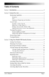
Contents
Contents
Document Drg Ref PR203-68-514-01
Contents
Contents
Page
Faults
Enable / Disable
Print (Function not availible)
Lamp Test
Weekly Test
View Events
Check Auto Config
Replace Devide
Test Dvice (Access Level 3)
Test Zone
Sounder Level Test Mode
Global Flashing LED On/Off
One Man Walk Test
Commission
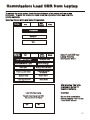
Load CDR from Laptop
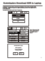
Download CDR to Laptop
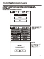
Auto Learn
Erase Log
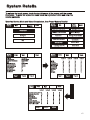
System Details
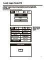
Load Logo from PC
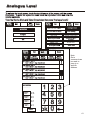
Analogue Levels
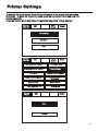
Printer Settings
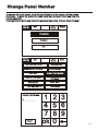
Change Panel Number
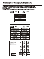
Number of Panels in Network
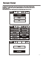
Screen Cover
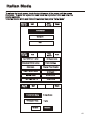
Italian Mode
Configure
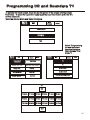
Programming I/O and Sounders T1
Programming I/O and Sounders T2
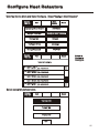
Panel Outputs
Auxiliary Board
Alarm Verification Feature
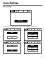
Sound settings
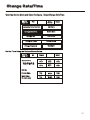
Change Date/Time
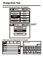
Change Zone Text
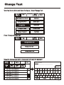
Change Text
Change Panel Text
44
45
46
47
48
49
50
51
52
53
54
55
56
57
58
59
60
61
62
63
64
65
66
67
68
69
70
71
72
73
74
75
76
77
78
Page
Configure Zones
Change Passcode
Add Zone
Delete Zone
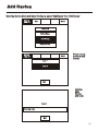
Add Device
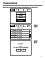
Delete Device
Configure Heat Detector
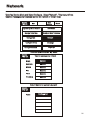
Network
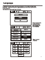
Language
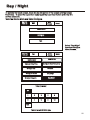
Day/night
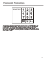
Password Protection
4.0 Appendix
4.0
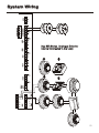
System Wiring
Spur Isolator Spec sheet
4 Way Sounder Circuit Spec sheet
Zone Unit Monitor Spec sheet
Shop Unit Monitor Spec sheet
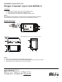
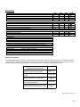
Single Channel Input Unit MCIM Spec Sheet
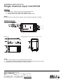
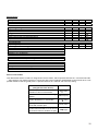
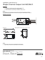
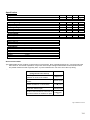
Single Channel Output Unit MCOM Spec Sheet
Single Channel Input Unit MCIM-C Spec Sheet
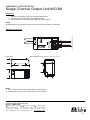
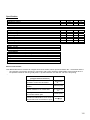
Single Channel Output Unit MCOM-S Spec Sheet
3 Channel I/O Unit Spec sheet
4 - 20mA Interface Spec sheet
Analogue Base & Sensor Spec Sheet
Internal & IP66 Wall Sounder Spec Sheet
Internal & IP66 Wall Sounder / Beacon Spec Sheet
Base Sounder Spec Sheet
Base Sounder / Beacon Spec Sheet
Loop Powered Beacon Spec Sheet
Call Point Spec Sheet
Remote Indicator
79
80
81
82
83
84
85
86
87
88
89
90
91
92
93
94
95
97
99
101
103
105
106
109
111
112
113
114
115
116
117
Contents
Contents
Section 1
System Installation and Design
6
Introduction
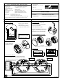
The Panel provides all of the sophisticated features required of a leading edge
analogue addressable fire system along with the simple operation and neat installation
demanded by installers and building users.
The panel can be flush or surface mounted and the generously sized metal back box
allows ample facilities for rear or top cable entries.
The panels are available in either Single or Two Loop Configuration.
A loop connected and a network connected repeater panel is available (see equipment
listing page 10)
A comprehensive range of ancillary devices is available to operate with the Panel,
including Optical, photo-thermal and heat detectors, base mounted and stand alone
sounders (including an IP67 version) a loop powered beacon and a wide range of input
and output interfaces.
Each of the Panel system components has been specifically designed to operate as
part of a Panel system, this provides an assurance that the panel, the detectors, the
interfaces and the ancillaries are all fully compatible with each other and that the full
range of system functionality is supported by each device.
7
Project Planning
The following is a typical program and timetable for a Panel installation project, once the
initial order has been received:
1.
Project Meeting
Installer and user to be present; system specifications, schematic diagram and
proposed circuit drawing to be available. Panel Installation & Commissioning
Guide to be provided.
2.
Equipment Fix
Typically 2 week's notice is required for equipment to be delivered. Cable to be
installed and bases/back boxes to be fitted. Then fire detectors, call points, alarm
sounders, isolator units and interface units to be installed.
3.
Address Schedule
Schedule of sensor locations to be completed by installer and returned to enable
System programming.
4.
Auto Learn
Fire panel/repeater panels to be installed and terminated. System to be powered
up by installer and auto learn mode activated (see Auto Learn section). System
to be tested and verified by installer, prior to final commissioning.
5.
Final Commissioning
Minimum 2 weeks notice is required from receipt of Address Schedule and
Commission request form. Cooper Lighting Service Engineer to attend site
implement/oversee the final commissioning procedures (see Commissioning
section), in conjunction with the installer.
8
System Design Guidelines
Guidelines
Systems should to the relevant local standards and codes of practice, for the UK this is
BS5839 part 1. The panel meets all the relevant requirements of BS5839 part 1: 2002.
Installation planning is simplified by the fact that every addressable device contains an integral
short circuit isolator. Care must be taken to ensure that local standards requirements
regarding aspects such as loop coverage, area covered by a single spur and cable
specification are observed.
There may be certain applications in which deviations from the code may be necessary and
these must be listed on the commissioning certificate. (See commissioning section)
Loop lengths
The maximum permitted loop length is 2 km measured from the near to the far terminals on
Panel Motherboard PCB. There is no minimum limit to loop length. Any wiring spurs off the
loop must be included within the 2 km limit. On long loop runs, the lengths of wiring rises and
falls (between floors, down to manual call points) must be included. Remember to include
these especially when taking loop lengths from plan drawings.
Loop loading - total number of addresses
The total number of addresses per loop is 20
0. this includes sensors
200.
sensors,, call points and all other
interfaces, loop repeaters etc.) When designing systems its
addressable items (e.g. interfaces,
recommended that allowances are made for future expansion, Short circuit isolators are
incorporated into every loop device, including Smoke sensors, heat sensors, sounders,
callpoints and interfaces. Therefore, no further fault protection is required , in the event of a
single fault, none of the devices connected to the loop will fail to operate as the fault will be
isolated by the two adjacent devices.
Spur connected devices downstream of a cable fault will cease to function.
Repeater panels
Each repeater unit requires one address and consumes no more current from the loop than a
smoke sensors. The repeater also requires a local mains supply and incorporates battery
backup.
Loop Loading System Verification
Loop load calculations should be carried out prior to instillation.
9
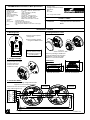
Compatible Equipment
COP range of system components
Order Code
Description
Dimensions WXHXD (mm)
COP1100
1 Loop panel
495 x400 x 180
COP1200
2 Loop panel
495 x400 x 180
COP1100NC
1 Loop panel c/w network card
375 x 357 x 50
COP1200NC
2 Loop panel c/w network card
375 x 357 x 50
COP3000PR
Passive repeater loop connected
332 x 270 x 92
COP3000PRNC
Passive repeater network connected
332 x 270 x 92
COPP420
Optical smoke detector
101 Dia x 33D
COPH430
Multi mode heat detector
101 Dia x 43D
COPOH450
Combined photo thermal detector
101 Dia x 43D
CAB300
104 Dia x 22D
COPBGU
Common mounting base for analogue detectors
Flush Callpoint
COPBGU-S
Surface Callpoint
85 x 85 x 53
COPBGU-WP
COPBS
Weatherproof Callpoint
108 x 108 x 65
Sounder base
102 Dia x 40D
CASC
Cover for MAS850
102 Dia x 13D
COPWS
Wall sounder
105 x 105 x 95
COPWS-WP
IP66 Wall sounder
108 x 108 x 103
COPB
Add. Beacon
95 Dia x 50D
COPSBB
Sounder beacon base
115 Dia x 42D
COPSB
Wall sounder beacon
105 x 105 x 95
COPSBB-WP
Wall sounder beacon IP65
108 x 108 x 103
COPIO
3 Channel I/O device
147 x 88 x 57
COPMIO
1 Channel output unit (mains rated)
180 x 130 x 60
COPZMU
Zone monitor unit
150 x 89 x 58
COPSUM
Shop unit Interface
150 x 89 x 58
COPSI
Spur Isolator
112 x 41 x 33
COPSC
4 Way sounder circuit controller.
300 x 300 x 74
85 x 85 x 30
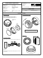
CF range of system components
Order Code
Description
Dimensions (mm)
CF1100
1 Loop panel
495 x400 x 180
CF1200
2 Loop panel
495 x400 x 180
CF1100NC
1 Loop panel c/w network card
375 x 357 x 50
CF1200NC
2 Loop panel c/w network card
375 x 357 x 50
CF3000PR
Passive repeater loop connected
332 x 270 x 92
CF3000PRNC
Passive repeater network connected
332 x 270 x 92
CAP320
Optical smoke detector
101 Dia x 33D
CAH330
Multi mode heat detector
101 Dia x 43D
CAPT340
Combined photo thermal detector
101 Dia x 43D
CAB300
104 Dia x 22D
CBG370
Common mounting base for analogue detectors
Flush Callpoint
CBG370-S
Surface Callpoint
85 x 85 x 53
CBG370-WP
CAS380
Weatherproof Callpoint
108 x 108 x 65
Sounder base
102 Dia x 40D
CASC
Cover for MAS850
102 Dia x 13D
CAS381
Wall sounder
105 x 105 x 95
CAS381-WP
IP66 Wall sounder
108 x 108 x 103
CAB382
Add. Beacon
95 Dia x 50D
CASBB384
Sounder beacon base
115 Dia x 42D
CASB383
Wall sounder beacon
105 x 105 x 95
CASBB383-WP
Wall sounder beacon IP65
108 x 108 x 103
CSI350
Spur Isolator
147 x 88 x 57
CIO351
3 Channel I/O device
180 x 130 x 60
CZMU352
Zone monitor unit
150 x 89 x 58
CMIO353
1 Channel output unit (mains rated)
150 x 89 x 58
CSC354
4 Way sounder circuit controller.
112 x 41 x 33
CSUM355
Shop unit Interface
300 x 300 x 74
MCIM
Single channel input unit
35 x 18.5 x 63
MCOM
Single channel output unit
35 x 18.5 x 63
MCIM-C
Single channel input unit
35 x 18.5 x 63
MCOM-S
Single channel output unit
35 x 18.5 x 63
CGI420
4 - 20 mA Interface
147 x 88 x 57
MRIAD
Addressablen Remote Indicator
87 x 87 x 49
85 x 85 x 30
10
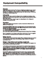
Equipment Compatibility
Sensors
Loop wired sensors must be of the Cooper soft addressed analogue type. Cooper
conventional detectors can be connected via a Zone Monitor Unit or Shop Unit
interface. The connection of other detector types via a Zone Monitor Unit or Shop
Unit interface is not recommended,
Call points
Loop wired call points must be the Cooper series soft addressed analogue type,
Cooper series conventional callpoints can be connected via a Zone Monitor Unit or
Shop Unit interface.
The connection of other callpoint types via a Zone Monitor Unit or Shop Unit
interface is not recommended,
Sounders
Loop powered addressable sounders must be of the Menvier 800 series soft
addressed analogue type.
Conventional sounders can also be connected either to the conventional sounder
circuits at the panel or to the loop via an addressable sounder controller interface
providing they meet the following:
1) They are suitable for operation between 18V and 28V.
2) They are polarised and suppressed.
3) The total alarm load is less than the rating of the panel / Alarm Power Interface.
Note: It is possible to use devices outside these requirements if they are supplied
with power from a separate source and switched via a suitable relay.
Relay circuits
There are Relay circuits built-in the standard Panel. Additional relays can be added
to the system by using Cooper soft addressing, Single Channel or 3 Channel
Input/Output Units.
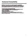
Relays / Auto-dialers and auxiliary equipment
A wide variety of relays and other equipment can be connected to the system, but
you should note the following constraints:
1) The Panel provides monitored outputs to drive fire and fault relays mounted in
external equipment. External relays should be suppressed. If a non-suppressed
relay is used then a diode can be connected as shown in the wiring diagram in the
appendix, to suppress any reverse EMF on the release of the relay which might
cause the panel to malfunction.
2) A 24V DC output is provided at the panel to make it easy to connect ancillary
equipment. Although the panel can supply a continuous quiescent load of up to
30mA, BS5839 precludes this practice and any ancillary equipment you connect
should only consume power in the alarm or fault mode to meet the requirements of
BS5839.
11
Equipment Compatibility
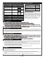
Additional instructions for electromagnetic compatibility
When used as intended this product complies with EMC Directive (89/336/EEC) and the
UK EMC regulations 1992 (SI 2372/1992) by meeting the limits set by the standards BS
5406 (Pts 2&3) 1988, EN50130-4 immunity and EN 61000-6-3 emission requirements.
The following installation guidelines must be followed.
1. External cables must be connected using the cable entries or knockouts provided.
2. When routing external cables inside the product they must be
a) Kept as short as possible
b) Routed close to the housing
c) Kept as far as possible from the electronics
Any modifications other than those stated in this manual, or any other use of this
product may cause interference and it is the responsibility of the user to comply with the
EMC and Low Voltage Directives.
12
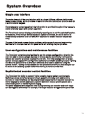
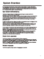
System Overview
Simple user interface
The main element of the user interface with is a large (120mm x 90mm visible area)
touch screen display, which provides comprehensive user information and also acts as
a multifunctional keypad.
Comprehensive context sensitive help information is provided throughout the menus to
assist unfamiliar users with system operation.
The Panel touch screen display automatically reconfigures to suit the selected function,
for example, if the change device text menu option is selected, the touch screen is
automatically formatted as a full QWERTY keyboard to enable fast and simple text
entry.
The use of the touch screen display enables a wide range of user and engineering
facilities to be incorporated into the panel whilst still offering simple operation.
User configuration and maintenance facilities
The Panel has comprehensive facilities for on site system configuration, whereby the
user can add or remove simple devices or change device text directly via the panel,
without the need for a service engineer to visit site. For initial configuration or major
system changes special PC configuration software is available enabling Cooper Lighting
and Security personnel to do this more efficiently than can be achieved using the
system screen. Exiting configurations can be uploaded to the PC so that changes can
be made to the existing system rather than having to revert to initial files.
Sophisticated sounder control facilities
The Panel has the ability to support highly complex ringing pattern requirements.
Multistage cause and effect programming is possible whereby each addressable
sounder or output interface can be programmed independently if required and can be
set to respond to specific addresses, specific detection zones, specific panels on a
networked system or standard global ringing.
The panel supports three separate sets of programming per sounder and each stage
can be triggered differently For example, if a single detector is triggered the panel can
13
System Overview
be programmed such that the sounder nearest to the detector operates immediately
and continuously, the remaining sounders in the affected zone operate in pulsed mode
and the other sounders delay for a selectable period to allow the cause of the alarm to
be investigated before global ringing commences.
Spur tolerant soft addressing
The Panel utilises intelligent soft addressing technology to greatly simplify the
installation and commissioning processes.
Once the system has been installed and the autolearn menu selected, the control panel
will automatically scan the detection loop and allocate each device with an address
number corresponding with its position on the loop, this avoids the traditional need for
manual addressing of the system devices which is time consuming and provides a
potential for error.
A major innovation with the Panel is the ability to incorporate spurs of analogue devices
which are fed from the loop by utilising a spur isolator.
Whenever the panel detects a spur, it breaks from allocating address numbers to the
loop wired devices, allocates address numbers to each of the devices on the spur in
sequence and then continues to address the devices on the main loop.
Every analogue device incorporates an integral short circuit isolator ensuring maximum
system integrity. A single short circuit will not disable any loop-mounted devices, the
isolators in the devices each side of the short circuit will operate and the control panel
will drive communication from both ends of the loop.
The spur isolator also incorporates a short circuit isolator such that in the event of a
short circuit on the spur, the integrity of the main loop will not be compromised.
Please refer to local standards e.g. BS5839 Pt1:2002 for details of the maximum
allowable are to be covered by a single spur.
Simple future expansion
The Panel is designed to ensure simplicity of future expansion.
If an additional device is added after the system has been programmed, the Panel will
allocate the next available address, it will not alter any of the existing address numbers
allocation thus enabling simple updating of as fitted drawings etc.
Similarly if a device is removed, the relevant address is saved as a spare address for
future use, the addresses of the remaining devices are not altered.
Multple Languages
The Panel supports a large number of languages as standard
14
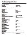
Technical Specification
Power Specification
Mains Fuse
Nominal Voltage
Nominal Current
: 1.6A Slow Blow
: 230 Vac + 10%, -15%
: 75mA
The Panel is protected by an internal thermal device, this requires no maintenance
Batteries
Number of Batteries
Manufacturer:
Capacity
Battery Fuse
Maximum battery current;
Standby current (mA)
:2
:YSP12-7
: 7 Ah
: 4A Quick Blow (F4)
: 3.5 Amps
: 100 (1 loop )
Inputs
Addressable Loops
Max Number
Max Loop Load per loop
Max Number of Addressable Devices per loop
Class Change
: 1 or 2 (Panel depending)
: 500 mA
: 150
: Operated by external volt free
contact
Outputs
Conventional sounder circuits
Number of sounder circuits
Total sounder Load
Sounder Circuit Fuses (F1/2/3/4)
End of line resistor
:2
: 1.5 Amps
: 1.6 Amp (Quick Blow)
: 6k8
Fire Routing Equipment
Max Load
Fused (PTC2)
End of Line resistor
: 60 mA
: 100mA polyswitch
: 6k8
Fire Protecting Equipment
Max Load
Fused (PTC3)
End of Line resistor
: 60 mA
: 100mA polyswitch
: 6k8
Fault Routing equipment
Max Load
Fused (PTC1)
End of Line resistor
: <10 mA
: 100mA polyswitch
: 6k8
Auxiliary Relays
The auxiliary relays provide fused volt free change over contacts. These contacts are not
monitored.
Max Load
: 24 Volts 1 Amp
Fuse (PTC4)
: 1.35 Amps polyswitch
15
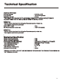
Technical Specification
Auxiliary 24V Supply
Nominal Voltage
: 24 Volts ±10%
Fuse (PTC5)
: 100 mA Polyswitch
Maximum current
: 30 mA
This output is not to be used for Fire protecting equipment or Fire alarm routing Equipment
Any power taken from the alarm system will effect the standby duration
RS485 Port
This is a serial output port for driving the Repeater panels, mimics etc..
This output is short circuit protected
Max Cable Length
: 2Km
Min Recommended cable size
: 1mm² (Screened)
RS232 Port
This is a serial output port for driving the Repeater panels, mimic etc..
This output is short circuit protected
`
Mechanical Specification
Weight including batteries
Weight excluding batteries
Dimensions (Standard batteries)
Type of Material (backbox)
Type of Material (Facia)
Flammability Rating
Total Number of knockouts
Diameter of Knock out
: 9 Kg
: 4 Kg
: 395mm(L) x 270mm(H) x 115mm(D)
: Mild Steel (Power Coated)
: PC/ABS
: UL 94 V0
: 11
: 20mm
TERMINAL BLOCKS : DO NOT USE EXCESSIVE FORCE WHEN TIGHTENING THE SCREWS ON
THE TERMINAL BLOCK
16
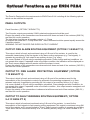
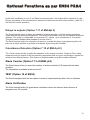
Optional Functions as per EN54 P2&4
The Panel is Designed to the requirements to EN54 Parts 2 & 4 including all the following options
which can be selected as required
PANEL OUTPUTS
Panel Sounders: (OPTION 7.8 EN54 PT 2)
Two Sounder outputs are provided. ONLY polarised equipment should be used.
Ensure the polarity of the connections are observed at all times and end of line resistors (6K8 5%)
are fitted for correct operation.
The total alarm load across all sounder outputs = 1.5 Amp
All outputs are fused with 1.6 Amp Glass fuse Alarm devices should be spread equally across the
2 sounder circuits.
WARNING: DO NOT EXCEED THE RATED OUTPUT CURRENT
OUTPUT FIRE ALARM ROUTING EQUIPMENT (OPTION 7.9 EN54 PT 2)
This output, which is fused, and monitored using a 6.8k end of line resistor, is used for the
automatic transmission of the fire signals to fire alarm routing equipment (e.g. Fire brigade). It
operates by providing 24 Volt output to an auxiliary device ( e.g. relay).
It is current limited to 30 mA using a resettable polyswitch. Class change and test conditions do
not operate this output. If operated under a fire alarm condition, the indication will be displayed on
the Touch screen display and will remain until the fire alarm is reset.
Ensure the polarity of the connections are observed at all times and end of line resistors ( 6K8 5% )
are fitted for correct operation.
OUTPUT TO FIRE ALARM PROTECTING EQUIPMENT ( OPTION
7.10 EN54 PT 2)
This output, which is fused, and monitored using a 6.8k end of line resisters used for the
transmission of the fire signals to controls for automatic fire protecting equipment (e.g. Door
released units etc).It operates by providing 24 Volt output to an auxiliary device ( e.g. relay).
It is current limited to 30 mA using a resettable. polyswitch. Class change and test conditions do
not operate this output. If operated under a fire alarm condition , this output remains energised until
the fire alarm is reset.
Ensure the polarity of the connections is observed at all times and end of line resistors ( 6K8 5% )
are fitted for correct operation.
OUTPUT TO FAULT WARNING ROUTING EQUIPMENT ( OPTION
9.4.1C EN54 PT 2)
This output, which is fused and monitored using 6.8k end of line resistor, is used for the
transmission of fault signals to fault warning routing equipment This output is monitored using 6k8
end of line resistor and it current limited to 30 mA. Under normal condition it operates by providing
12vdc which can be connected directly to a 12v auxiliary device( relay).It is current limited to 30
mA.
17
Optional Functions as per EN54 P2&4
Under fault conditions or even if the Panel is powered down, this output will be switch to O volts.
Ensure the polarity of the connections is observed at all times and end of line resistors ( 6K8 5% )
are fitted for correct operation.
Delays to outputs (Option 7.11 of EN54pt 2)
The Panel has the option to delay the operation of panel sounders, the fire routing equipment
output and the fire protecting Equipment. This delay is selectable using the site installer download
software .The delay is configurable in increments of 1 minute up to a maximum of 10 minutes.
This delay can be enabled and disabled at access level 2.
The Panel has the facility for a specific call point to override this delay by programming this call
point via an input interface to provide an evacuate signal using site Installer.
Coincidence Detection (Option 7.12 of EN54 pt 2)
The Panel has the facility to inhibit the operation of the output sounders, Output to Fire routing
equipment and the output of the fire protecting equipment until one more confirmatory signals are
received from different zones. This feature is programmable using Site Installer Software.
Alarm Counter (Option 7.13 of EN54 pt2)
The Panel has provision to record the number of instances that the CIE enters the fire alarm
condition.
The information is available at access level 2.
TEST (Option 16 of EN54)
The Panels equipped with the test option and can be implemented by either Zone or Address.
Alarm Verification
The Panel has the facility for global alarm verification where the detector alarm decision is
integrated over 30 seconds.
18
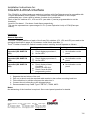
Cable & Wiring
Only the cable types listed below are allowable for loop connections.
1.
2.
3.
4.
Enhanced Fire TUF
Fire TUF™
FP200
MICC
When choosing your preferred cable type, you must take note of the following cable and
wiring requirements.
1. The cable must be 2 core screened with an over sheath.
2. Maximum loop length with any of the above cables is 2KM
3. Maximum volt drop must be limited to 7 volts.
2. The conductors should be 1.5mm minimum.
3. Multicore cable should not be used for detector wiring.
4. Different loops should NEVER be run within the same cable.
5. Loop feeds and returns should never be used within the same cable.
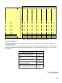
Cable Resistance
Co re Di a m e te r
1.0m m²
1.5m m²
2.5m m²
4.0m m²
Typi ca l FP 200 Re sista nce
18.1 Ohm s/ km /Core
12.1 Ohm s/ km /Core
7.41 Ohm s/ km /Core
4.61 Ohm s/ km /Core
19
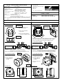
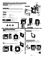
Installation
The panel should be installed in a clean, dry, reasonably well ventilated place, and not in
direct sunlight. Temperatures in excess of +45°C and below -10°C may cause problems, if
in doubt consult Technical Support.
Support. The panel should be located away from any potential
hazard, in a position where it is readily accessible to authorised staff, and the fire services,
ideally on the perimeter of a building near a permanent entrance. Mount the panel to the
wall using the drill template provided. Do not drill through the panel to the wall as dust will
contaminate the circuitry.
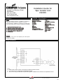
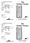
Installation Guide
It is of vital importance that accurate details are kept of the exact wiring route in
order to determine which address has been allocated to each device.
This example can be
seen again and more
clearly in Appendix
(A) System Wiring
Any 800 Series Analogue Detector
can be Connected to the Loop
+
1 -
+
1 -
MAINS
+
2 -
SOUNDER CIRCUIT
+
2 -
NO
C
AUX
RELAY
NC
-
+
FAULT
RELAY
Tx+ Tx-
RS485
0V +26V
-
FIRE R/E
+
-
+
NETWORK CIRCUIT
LOOP2
F-
E
F+
FIRE P/E
CLASS
CHANGE
S+
F+
F-
LOOP2
LOOP1
E
E
E
N
EARTH
LOOP1
L
S-
E
!
E
!
EARTH
!
EARTH
!
EARTH
!
!
Never carry out insulation tests on cables connected to electronic equipment.
DO NOT OVER TIGHTEN TERMINAL CONNECTOR SCREWS
Always use the correct type of cables specifically designed for the operation of fire
detection and alarm circuits.
Always adhere to volt drop limitation when sizing cables
Always observe polarity throughout. Non colour coded conductors should be
permanently identified.
Screen continuity must be maintained throughout the entire loop circuit including at
each junction point and at each device, terminals are provided on each device to
facilitate this.
The screen should be earthed at the connection point provided at the Panel and not
at any other point. Both the loop start and the loop end must be connected to the
appropriate earthing points.
Care must be taken to avoid connecting the screen to the earthed body of any
metal devices, enclosures or cable containment. The screen or drain wire of the
loop cables should not be considered as safety earth and therefore should not be
connected to terminals marked with the earth symbol, except at the panel, and
should not be insulated with green and yellow sleeving.
The Panel utilises intelligent soft addressing technology to greatly simplify the
installation and commissioning processes. Once the system has been installed and
the autolearn menu selected, the control panel will automatically scan the detection
loops and allocate each device with an address number corresponding with its
position on the loop, this avoids the traditional need for manual addressing of the
system devices which is time consuming and provides a potential for error.
EARTH
!
!
!
S+
S-
20
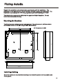
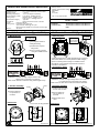
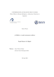
Fixing details
Read all the installation instructions before commencing with the installation. The
installation of this panel must be carried out by a suitably qualified /trained person. The
installation must comply with IEE wiring regulations and with BS5839 part 1 2002
The electronic components within the fire panel are Static Sensitive. Do not
touch the electronics directly.
Mounting the Backbox
The Panel can be surface mounted and recessed . To surface mount; drill three holes
and fix the backbox to the wall using suitable screw fixings.
128.20
All Dimensions in MM
345.00
229.80
141.80
270.00
50.00
325.00
Installing Cabling
Once the backbox is mounted the next stage is to install the power and loop cables and
fit the glands.
21
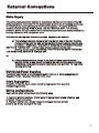
External Connections
Mains Supply
The mains supply should be installed in accordance with the current edition of the IEE
wiring regulations. Connection to the mains supply must be via an isolating device (e.g.
an isolating fuse) reserved solely for the fire alarm system. The cover should be
coloured red and labelled “FIRE ALARM - DO NOT SWITCH OFF”. The isolating
protective device should be secure from unauthorised operation and ideally installed in a
securely closed box with a breakable cover.
An additional warning label should be provided, depending on whether:a) The isolating protective device is fed from the live side of the main isolating
device in which case the label on the isolating protective device, should read
in addition - “WARNING: THIS SUPPLY REMAINS ALIVE WHEN THE MAIN
SWITCH IS TURNED OFF”. A further label should be placed on the main
isolating device reading “WARNING: THE FIRE ALARM SUPPLY REMAINS
LIVE WHEN THIS SWITCH IS TURNED OFF.
Or
b) If the isolating protective device is fed from the dead side of the main
isolating device, a label should be fixed to the main isolating device reading
“WARNING: THIS SWITCH ALSO CONTROLS THE SUPPLY TO THE FIRE
ALARM SYSTEM”.
Distributed Power Supplies
The above also applies to any distributed power supply (i.e. mains connections for
Repeater Panels , Sounders Controller Units, etc.)
Cable Segregation
All cables for the fire alarm system should be segregated from any other
cables/wiring/services.
Wiring configurations
Spurs can be taken off the loop in the following ways:
1) The Zone Monitor Interface - Allows up to 20 conventional smoke detectors and
unlimited Cooper call points.
2) The Spur Isolator Unit - Allows a zone of analogue Sensors and call
points to be directly spurred off the loop.
22
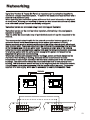
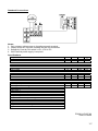
Networking
Up to One Hundred & Twenty Six Panels or repeaters can be networked together to
operate as a single networked system. To achieve this each panel must be fitted with a
network card (Optional Extra)
When operating as a networked system all fire and fault event information is displayed
at every panel, silencing and resetting of alarms can also be carried out from any panel
on a networked system if panels are suitably configured.
Networked panels are connected using a loop topology as illustrated.
Networked panels can be used as active repeaters, alternatively a low cost passive
repeater is available.
This can either be connected a loop of an individual panel or it can be connected to the
network.
The recommended network cable for the network connection between panels is an
enhanced Firetuf cable Manufactured by Draka cables (part number 910234.
910234.)
Screen continuity must be maintained throughout the entire network circuit including at
each junction point. The screen should only be earthed at the connection point provided
at the first panel and not at any other point. The screen or drain wire of the network
cable should not be considered as a safety earth and therefore should not be connected
to terminals marked with the earth symbol, except at the panel, and should not be
insulated with green and yellow sleeving
Where the network cable passes between buildings, screen continuity should not be
maintained from building to building. A booster device must however be used
irrespective of cable length and should be fitted at a suitable point in the link between
buildings. The cable screen should be connected to the earth of one panel in each
building. 102 S terminator should be fitted at the beginning and the end of the network.
If the distance in the network exceeds 1KM the booster should be used. The booster
requires 24V local supply, which can be connected to nearest Addressable Panel
Network Cable
TOP
A
B
X
Y
E
TOP
Network Terminal
on main PCB
(Panel 1)
A
B
X
Y
E
Network Terminal
on main PCB
(Panel 2)
23
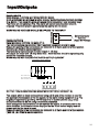
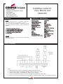
Input/Outputs
PANEL INPUTS
Class Change: ( OPTION NOT REQUIRED BY EN54)
A pair of terminals are provided for class change. By shorting these terminals together
(e.g. Switch, Time clock) the alarm will sound (Panel sounders + loop sounders only).
The Panel will not indicate a Fire. The alarm will cancel when the short circuit is
removed. If the short circuit is not removed the alarms will not cancel.
WARNING: NO VOLTAGE SHOULD BE APPLIED TO THIS INPUT
+
Class Change
-
Switch/Contactor
timer etc.
(Apply NO voltage)
PANEL OUTPUTS
Panel Sounders: (OPTION 7.8 EN54 PT 2)
Two pairs of outputs are provided. ONLY polarised equipment should be used.
Ensure the polarity of the connections are observed at all times and end of line resistors
(6K8 5%) are fitted for correct operation.
The total alarm load across all sounder outputs = 1.5 Amp
All outputs are fused with 1.6 Amp Glass fuse Alarm devices should be spread equally
across the 4 sounder circuits.
WARNING: DO NOT EXCEED THE RATED OUTPUT CURRENT
All Sou nde rs must be polarise d
Both sounder circuits must
Be terminated with a
6K8W end of line resistor
OUTPUT FIRE ALARM ROUTING EQUIPMENT (OPTION 7.9 EN54 PT 2)
This output, which is fused and monitored using a 6.8k end of line resistor, is used for
the automatic transmission of the fire signals to fire alarm routing equipment (e.g. Fire
brigade). It operates by providing 12 Volt output to an auxiliary device ( e.g. relay).
It is current limited to 30 mA using a resettable polyswitch.
Class change and test conditions do not operate this output. If operated under a fire
alarm condition, the indication will be displayed on the Touch screen display and will
remain until the fire alarm is reset.
Ensure the polarity of the connections are observed at all times and end of line resistors
( 6K8 5% ) are fitted for correct operation.
24
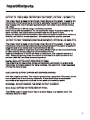
Input/Outputs
OUTPUT TO FIRE ALARM PROTECTING EQUIPMENT ( OPTION 7.10 EN54 PT 2)
This output, which is fused and monitored using 6.8k end of line resistor is used for the
transmission of the fire signals to controls for automatic fire protecting equipment (e.g.
Door release units etc).It operates by providing 24 Volt output to an auxiliary device (
e.g. relay).
It is current limited to 30 mA using a resettable polyswitch.
Class change and test conditions do not operate this output. If operated under a fire
alarm condition , this output remains activated until the fire alarm is reset.
Ensure the polarity of the connections is observed at all times and end of line resistors (
6K8 5% ) are fitted for correct operation. All activated devices must be polarised.
OUTPUT TO FAULT WARNING ROUTING EQUIPMENT ( OPTION 9.4.1C EN54 PT 2)
This output, which is fused and monitored using 6.8k end of line resistor is used for the
transmission of fault signals to fault warning routing equipment This output is monitored
using 6k8 end of line resistor and it current limited to 30 mA.
Under normal conditions it operates by providing 24vdc which can be connected directly
to a 24v auxiliary device( relay).It is current limited to 30 mA.
Under fault conditions or even if the Panel is switched off, this output will switch to 0
volts. Ensure the polarity of the connections is observed at all times and end of line
resistors ( 6K8 5% ) are fitted for correct operation.
Auxiliary Relay (OPTION NOT REQUIRED BY EN54)
This output is a volt free contact, which is protected by a polyswitch. It is rated at 24
Volts 1Amp. If operated under a fire alarm condition , this output will remain energised
until the fire alarm is reset
AUXILIARY DC OUTPUT (OPTION NOT DEFINED BY EN54)
A 24 Vdc output is provided. This output is protected by a polyswitch. This output can be
used to power fire or fault auxiliary equipment. Please ensure that all equipments
connected to this output will only draw current when a fire condition exists.
WARNING:- DO NOT EXCEED THE RATED OUTPUT CURRENT
Mimic Output (OPTION NOT REQUIRED BY EN54)
This RS485 output is used to send data to a mimic display or a repeater panel. The
maximum distance is 2km.
25
Maintainance
Functions: See User Manual for full details.
Daily Inspection
Check that only the green “POWER ON” indicator shows. Inspect for any fault
indication. Notify any faults to a system supervisior.
Weekly Test
Check indicators.
Press Supervisor mode on the top left of the touch screen. Enter passcode.
Select “others” tab. Press the button labeled weekly test, confirm you wish to
perform the test and the amber “System Test” LED will light. The panel will stay in
the weekly test mode for 5mins before resetting. During the weekly test, trigger a
smoke detector or call point and check the fire panel registers the device and
illuminates the correct zonal indicator. Trigger a different device every time a
weekly test is performed ensuring devices are tested in rotation until all have been
checked. It is advisable to develop a detailed a building plan highlighting devices
and locations to aid testing. The panel will reset automatically once the 5mins have
elapsed. If no devices are triggered during the weekly test the panel will abort the
test and reset after 5mins. Record weekly test in the table provided in this log
book.
Quarterly
Check all previous log book entries and verify that remedial action has been taken.
Carry out the weekly test. Visually examine the batteries and their connections, by
loosening the screws behind printer door and opening the hinged front from the
right hand side.
Disconnect the mains supply and check that the battery is capable of supplying the
alarm sounders, by operating a call point.
Annual Test
As Weekly Test and Quarterly Test above. Additionally test all sensors and call
points and check operation.
Every 2-3 Years
Replace or return the smoke detectors for cleaning to ensure correct operation and
freedom from false alarms. Special equipment is required for cleaning smoke
detectors.
Every 5 Years
Replace sealed lead acid battery.
Cleaning: When cleaning the panel, use a moist cloth. Do not use solvents or
harsh abrasives.
Printer Paper Order Code: OPTION NOT AVAILABLE
26
Section 2
Commissioning
27
Commissioning
Commissioning mode
Walk test mode allows a single engineer to test the various detectors and call points on a
system without always having to return to the panel either to reset the system or silence
the alarms. When in COMMISSIONING MODE, the system operates as normal except
that when a detector or call point goes into alarm, the alarms only operate for a few
seconds and then will silence. The panel then tries to reset the device automatically and,
if successful, the alarms are operated again for a few seconds and the installation
engineer can move on to the next detector. After a full test has been carried out the
engineer can check the order in which the detectors/call points were operated using the
DISPLAY LOG mode. This information can also be printed on the optional printer.
For details of how to access commissioning mode, please refer to page 64
When the panel is in “Walk Test Mode” the control panel inserts a different code into the
log and also onto the print-out. This is to distinguish between when a device has been
tested in “Walk Test Mode” and when a device has been triggered while in normal
operation.
The following differences will occur:
a) When in the LOG mode, "One man walk test”" will appear on the display followed by
the address text and device type.
b) On the printout a “One man walk test” message will appear will appear followed by the
address text and device type.
C)During a real fire “FIRE !” Will appear on the display followed by the address text and
device type.
28
Configuration
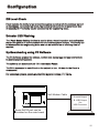
DB Level Check
Panel includes the facility to test and set the system sounders with the minimum amount
of disturbance. In sounder test mode, the sounders will sound for 30 seconds on then
30 seconds off. This facility can be accessed via the engineering menu.
Detector LED Flashing
The Panel Sensor flashing function is used to allow a visual inspection and confirmation
that the fire panel is in communication with the installed system devices. This facility can
be accessed via the engineering menu and can be switched on or off at any time as
required.
Up/downloading using PC Software
The PC Software enables the address, location text, device type and any comments to
be downloaded to the panels.
The software can download to all 126 networkable Panels.
The PC is connected to each Panel on the network in turn. All data for the Panel is
downloaded.
For networked systems, panels are identified by panel number, P1, P2 etc.
Null Modem Cable
A.serial Output
B. USB Output
Via
USB Convertor
Serial Rs232 port can be
locatated on the main board
29
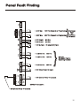
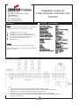
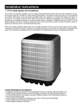
Panel Fault Finding
L
N
MAINS
E
+28V Fire (Depends on Programming)
V
= -0.6V Mon
+28V Fire (Depends on Programming)
W
= O/C Normal
S/C Fire
NC
W
= S/C Normal
O/C Fire
V
= 12V No Fault
V
= -O.6V-No Fire
28V Fire
V
= -O.6V-No Fire
28V Fire
V
= -O.6V-No Fire
28V Fire
V
= 28V (Open Circuit, No Input)
V
= 22V (Device Fitted) 0V (Unused)
EARTH
+
2 -
2 -
= -0.6V Mon
C
1 -
+
SOUNDER CIRCUIT
1 -
}
+
+
NETWORK CIRCUIT
E
V
EARTH
See Scope
Plots
for
Monitoring
Conditions
NO
AUX
RELAY
+
FAULT
RELAY
0V (short CCT) Fault
EARTH
Tx+ Tx-
RS485
0V +26V
-
FIRE R/E
+
EARTH
+
FIRE P/E
EARTH
CLASS
CHANGE
E
F+
LOOP1
S+
F-
S-
v
LOOP1
E
}
No Fires
See Scope Plots for
Monitoring Condition
E
E
S-
F-
LOOP2
F+
S+
LOOP2
REPEAT FOR LOOP 2
= 22V (Device Fitted) 0V (Unused)
30
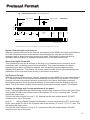
Protocol Format
Fig. 1 Full Protocol Format
(Not including Repeaters)
Panel to Device
Device to Panel
1.1 ms
300us
2ms
Last Bit Only
1.36 ms
300us
24v
typ
7.5v
0v
Mode
Byte 1
Byte 2
Byte 3
Parity
Command
Start
Response
8 bits
ID
5 bits
Flags
3 bits
Address
8 bits
Loop Current
See Fig 4 for detail
Each Packet of Comms above must be separated by a gap of 20ms minimum where the line is held at 24v
Normal Communications to Devices:
With the command bits set for the 'Normal' command and the MSB of the three mode bits set
at 0, this shortened version of the Normal communications to each device allows the
analogue reply or status from each device to be read. This format of communication is
generally used throughout all background supervision of the addressable loop.
Alarm Interrogate Command:
This command is seen by all devices on the loop, so no address byte is required, and is
periodically sent out during normal communications. This command allows any device
experiencing an alarm condition to respond, with call points given the highest priority,
reporting their address. This causes the control panel to break off from general background
supervision of the loop and focus directly on the device in question.
Full Protocol Format:
With the command bits set for the 'Normal' command and the MSB of the three mode bits set
at 1, the long version of the Normal communications can be sent to any device. This would
normally be done by the panel following a response to the Alarm Interrogate command,
allowing the panel to check the device address, ID and confirm that the analogue reply, or
status, is truly an alarm condition before actioning the panel sounder outputs, for example.
Viewing the Voltage and Current waveforms at the panel:
Loop 1: Using a Digital Storage Oscilloscope, connect one channel to R34 on the Loop Driver
Card; probe 0V clip to the 'in-board' side of the resistor; I/P to the 'out-board' side. This will
display the loop current.
Connect the other channel to Loop 1, S+ terminal on the main mother board. DO NOT
connect the 0v clip of this probe.
Loop 2:
Using a Digital Storage Oscilloscope, connect one channel to R?? on the Loop
Driver Card; probe 0V clip to the 'in-board' side of the resistor; I/P to the '????????' side. This
will display the loop current.
Connect the other channel to Loop 2, S+ terminal on the main mother board. DO NOT
connect the 0v clip of this probe
31
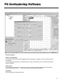
PC Comissioning Software
Device Input Programming
Fire
Fault
Reset
Silence
Pre-Alarm
-> panel reports fire from device.
-> panel reports fault from device.
-> panel resets.
-> silence all currently active sounders.
-> panel reports pre-alarm from device.
Non-Latching-> device won't latch in alarm condition, used in conjunction with isolates.
Day / Night
devices affected :
Optical-Heat -> mode changes between heat or optoheat mode
Heat
-> mode changes between Heat A1R and Heat CS
Isolate Zone / Address
user can define between zones or addresses to be isolated on activation of the device.
The isolate list button enables the user to enter upto 8 unique zones or addresses.
If non-latching has been enabled, Isolated devices can be un-isolated as the triggered device
returns to normal operation. (a call point keyswitch is an example for this application)
32
PC Comissioning Software
Device Outputs
Delay configuration
The output of a device when triggered can be delayed - based on a user defined value
in minutes.
This programming option is enabled when a value other than zero is entered inside the
'Delay' window.
D Override
This option is a manual intervention override, when enabled (check in box) the delay
can be overridden from
any call point on the loop when triggered.
DayNight
See coincidence detection below
33
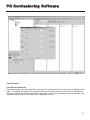
PC Comissioning Software
Panel Outputs
Coincidence detection
Each panel output can be assigned a unique list of zones derived from the zones available on the
loop, to activate this output, two unique zones from this list have to be be in fire or alternatively
any zone outside this list will trigger the output also. When the 'coincidence' box is checked - the
'Allocate device' button allows the user to populate this list.
34
Section 3
Panel Controls & Indicators
35
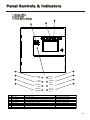
Panel Controls & Indicators
1. System LED’s
2. Zonal LED’s
3. Touch Screen Display
3
2
1
5
1
2
Power
ON
3
FIRE
4
LED Name
1
2
3
4
5
6
7
8
Power On
Fire
General Fault
General Disable
Power Fault
Sys tem Fault
Test
Sounder
6
Power
Fault
7
System
Fault
General
Fault
TEST
General
Disable
Sounder
Disable
Fault
8
Function
Action
Shows Panel is On
Indicators Panel has Det ected a Fi re
Monitors Devices for Faults e.g. S moke detec tors/ Sounders
Monitors Fire Panel for Fault s
Monitor Internal B attery Charger
Monitors Fire Panel for Fault s
Supervisor/Engineer i s Testing t he Sys tems
Indicates the Sounder St atus
Check Indic ator is Ill uminated
Impliment F ire Act ion Procedure
Report to Sy stem S upervisor
Report Fault t o Service Dept
Report Fault t o Service Dept
Report Fault t o Service Dept
Report to Sy stem S upervisor
Check wit h Sys tem Supervisor
36
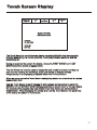
Touch Screen Display
Supervisor
FRE Off
Fires
0
Pre
Alarms 0
Faults
0
Disabled
0
System Healthy
XX Zones Active
Tuesday
dd-mm-yyyy
16:25.25
BST On
The Touch Screen is a multi-function display consisting 320x240 dots featuring high
intensity backlighting. In normal operation, the display indicates as above with the
backlighting off.
During an event on the system the display shows the FIRST EVENT and LAST
EVENT plus other events as space allows.
The last 2 lines are normally used to display the total number of events, but they are
also used for scrolling fire conditions, faults, pre alarms or disabled devices
independently or for displaying a reduced menu when in fire condition.
When an event occurs the Touch Screen backlighting comes on unless there is a mains
power supply fault.
Use the Touch Screen to scroll through all active events on the system by using the
SCROLL UP and SCROLL DOWN buttons (available at access level 1). You can display
the contents of the log and also view details of any fires, faults, pre-alarms,faults or
disablements.. When displaying the system menu on the Touch Screen, the last 5 lines
of the display are shown in reverse text.
37
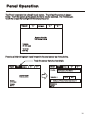
Panel Operation
The Panel is operated via a backlit touch screen. The default fire screen is shown
below. From this screen all the panels functions can be operated. The first time you
touch the screen the backlight will illuminate the panel.
Supervisor
FRE Off
Fires
0
Pre
Alarms 0
Faults
0
Disabled
0
System Healthy
XX Zones Active
Tuesday
dd-mm-yyyy
16:25.25
BST On
Pressing a field will highlight it and forward to the next screen as shown below.
Touch the screen here to view details
Supervisor
FRE Off
Fires
1
Pre
Alarms 0
Faults
0
Disabled
0
First Fire
System Healthy
10 Zones Active
Tuesday
dd-mm-yyyy
16:25.25
BST On
Fires
1
Supervisor
FRE Off
Pre
Alarms 0
Faults
0
Disabled
0
Meeting Room 1, Building 1, 1st floor
Loop: 1, Zone: 2, Type: Optical
Total Fires= 1
Print All
Help
001 FIRE! Meeting Room 1, [Optical] (Ana = 169)
Building 1, 1st floor, Panel 1, Loop1, device 4
Tuesday
Dd-mmm-yyy
16:25.25
BST On
38
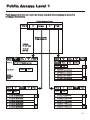
Public Access Level 1
Public access level does not require an access code and allows anybody to review the
functions outlined below.
Public Access Level
Supervisor
FRE off
Pre
Alarms 0
Fires
0
Faults
5
Disabled
/ Test
System Healthy
10 Zones Active
Tuesday
dd-mm-yyyy
16:25.25
BST On
Supervisor
FRE off
First Fire
Fires
1
Pre
Alarms 0
Faults
0
Disabled
/ Test
12:26:23 Device 1, Zone 1
Lp: 1, Ad:1, Z:1, Opto/thermal, [69]
Print All
Total Fires= 1
Supervisor
FRE off
Fires
0
Pre
Alarms 6
Faults
0
Show
Addresses
Show
Zones
Show
I/O
Show
Test Zone
Print All
Help
Disabled
/ Test
001 Device 2, Zone 1
Loop 1, Zone: 1, Type : Opto/thermal
Help
002 Device 3, Zone 1
Loop 1, Zone: 1, Type : Opto/thermal
003 Device 4, Zone 1
Loop 1, Zone: 1, Type : Opto/thermal
Tuesday
dd-mm-yyyy
16:25.25
BST On
004 Device 5, Zone 1
Loop 1, Zone: 1, Type : Opto/thermal
Supervisor
FRE off
Fires
0
Print All
Help
Pre
Alarms 6
Faults
0
Disabled
/ Test
Supervisor
FRE off
Fires
0
Print All
Help
Pre
Alarms 6
001 03-Jun-03 12:51 Warning! : Device1
Lp: 1, Ad: 1, Z: 1, Opto/thermal [69]
001 12:31:59 Fault! : Device1
Lp: 1, Ad: 1, Z: 1, Opto/thermal [0]
002 03-Jun-03 12:51 Warning! : Device2
Lp: 1, Ad: 2, Z: 1, Opto/thermal [69]
002 12:32:59 Fault! : Device2
Lp: 1, Ad: 2, Z: 1, Opto/thermal [69]
003 03-Jun-03 12:51 Warning! : Device3
Lp: 1, Ad: 3, Z: 1, Opto/thermal [69]
003 12:33:59 Fault! : Device3
Lp: 1, Ad: 3, Z: 1, Opto/thermal [69]
004 03-Jun-03 12:51 Warning! : Device4
Lp: 1, Ad: 4, Z: 1, Opto/thermal [69]
004 12:34:59 Fault! : Device4
Lp: 1, Ad: 4, Z: 1, Opto/thermal [69]
005 03-Jun-03 12:51 Warning! : Device5
Lp: 1, Ad: 5, Z: 1, Opto/thermal [69]
005 12:35:59 Fault! : Device5
Lp: 1, Ad: 4, Z: 1, Opto/thermal [69]
Faults
5
Disabled
/ Test
39
Evacuate (Access Level 2)
To activate the touch screen, touch the top left corner of the screen until the screen
illuminates. To enter the supervisor mode touch the supervisor button and enter the
passcode.
Enter the Supervisor Mode Passcode and select “Evacuate” on the menu at the top of
the screen.
Supervisor
FRE off
Evacuate
Mute
Buzzer
Silence
Alarms
Reset
Others
View Fires
AC = 0
Faults
Disabled
View Pre
Alarms
Select “Yes” to evacuate the building.
This will activate ALL sounders
and activate all panel relays
Do you wish to continue?
Yes
No
40
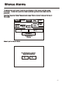
Silence Alarms
To activate the touch screen, touch the top left corner of the screen until the screen
illuminates. To enter the supervisor mode touch the supervisor button and enter the
passcode.
Enter the Supervisor Mode Passcode and select “Silence Alarms” button as the top of
the screen.
Supervisor
FRE off
View Fires
AC = 0
Evacuate
Mute
Buzzer
Silence
Alarms
Reset
Others
View Pre
Alarms
Faults
Disabled
Zone: 0
I/O
Addresses: 0
Touch button to
View list
Select “yes” to silence Alarm.
This will silence ALL sounders
Do you wish to continue?
Yes
No
41
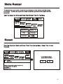
Mute Buzzer
To activate the touch screen, touch the top left corner of the screen until the screen
illuminates. To enter the supervisor mode touch the supervisor button and enter the
passcode.
Enter the Supervisor Mode and Select “Mute Buzzer” from the Top Menu
Supervisor
FRE off
Silence
Alarms
Evacuate
Mute
Buzzer
Reset
Faults
Others
View Fires
View Pre
AC = 19
Alarms
Disabled
Enable/Disable
Weekly Test
Print
View Log
Lamp Test
Check
Config.
Reset
Enter the Supervisor Mode and Select “Reset” from the top Menu. Select “Yes” to reset
the panel.
Supervisor
FRE off
View Fires
AC = 19
Evacuate
View Pre
Alarms
Silence
Alarms
Mute
Buzzer
Reset
Others
View
Disabled
View
Faults
001 14:22:49
Mains Failure
This will Reset the Panel
Do you want to continue?
Yes
No
Faults = Short circuits, broken detectors etc.
To remove faults from this list:
1) Fix Fault
2) Reset Panel
42
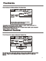
Pre-Alarms
Enter the Supervisor Mode and Select “Pre-Alarms” tab.
Supervisor
FRE Off
Evacuate
Silence
Alarms
Disabled
Fires
AC = 0
Mute
Buzzer
Faults
Reset
Others
Pre
Alarms
Pre-alarm = Some smoke /heat but below fire threshold
These warnings will appear and disappear
A pre-alarm is shown when a detector appears to register heat or smoke but in a
quantity that is insufficient to warrant an alarm.
Pre-alarm may indicate a build up of dirt in a smoke detector which can be interpreted
by the detector as smoke presence.
Disabled Devices
Enter the Supervisor mode and Select the “Disabled” tab.
Supervisor
FRE Off
Fires
AC = 0
Evacuate
Pre
Alarms
Silence
Alarms
Mute
Buzzer
Faults
Reset
Others
Disabled
Zone: 0
I/O
Addresses: 0
Touch button to
View list
The individual buttons show which devices and the number of devices which have been
disabled. Press one of the buttons to display detailed information for a particular
category
43
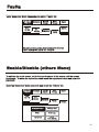
Faults
Enter Supervisor Mode Passcode and select “Faults” tab.
Supervisor
FRE Off
Fires
AC = 0
Evacuate
Pre
Alarms
Mute
Buzzer
Silence
Alarms
Reset
Others
Disabled
Faults
Pre-alarm = Some smoke /heat but below fire threshold
These warnings will appear and disappear
Enable/Disable (others Menu)
To activate the touch screen, touch the top left corner of the screen until the screen
illuminates. To enter the supervisor mode touch the supervisor button and enter the
passcode.
Enter the Supervisor Mode passcode and select the “Others” tab.
Supervisor
FRE Off
Fires
AC = 0
Evacuate
Pre
Alarms
Silence
Alarms
Disabled
Mute
Buzzer
Faults
Enable/Disable
Weekly Test
Print
View Log
Lamp test
Reset
Others
Check
Auto Config.
44
Enable/Disable
Supervisor
FRE off
Evacuate
Silence
Alarms
Mute
Buzzer
The Enable/Disable
feature allows the
operator to disable part
or a whole system by
the sub menus shown
on the left.
Reset
Enable/Disable Address
Enable/Disable Zone
Enable/Disable I/O
Enable All
Network Enable / Disable
Exit
Supervisor
FRE off
Evacuate
Silence
Alarms
Mute
Buzzer
Reset
Show
All
Show
Detectors
Show
Alarms
Show
I/O Units
Exit
001 Device 1, Zone 1
Loop: 1, Zone: 1, Type: Opto/thermal
Enabled
002 Device 2, Zone 1
Loop: 1, Zone: 1, Type: Opto/thermal
Disable
003 Device 3, Zone 1
Loop: 1, Zone: 1, Type: Opto/thermal
Disable
004 Device 4, Zone 1
Loop: 1, Zone: 1, Type: Opto/thermal
Enabled
005 Device 5, Zone 1
Loop: 1, Zone: 1, Type: Opto/thermal
Disable
Supervisor
FRE off
Exit
Evacuate
Silence
Alarms
Mute
Buzzer
Supervisor
FRE off
Silence
Alarms
Evacuate
Mute
Buzzer
Reset
Fire Routing: Enabled
Input 1: Enabled
Fire Protection: Enabled
Input 2: Enabled
Delayed:Enabled
Input: Disabled
Aux Relay: Enabled
Sounder 1: Enabled
Fault Relay: Enabled
Sounder 2: Disabled
Exit
Reset
Touch “Enabled” button to Disable
Touch “Disabled”button to Enable
Zone 001 Zone 1
Enabled
Zone 002 Zone 2
Disabled
Zone 003 Zone 3
Disabled
Zone 004 Zone 4
Enabled
Enable all Devices?
Do you want to continue?
No
Yes
Supervisor
FRE off
EXIT
NETWORK ENABLE / DISABLE
PANEL NUMBER
0
1
2
3
Del
4
5
6
Ok
7
8
9
45
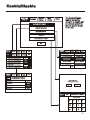
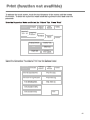
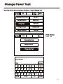
Print (function not availible)
To activate the touch screen, touch the top left corner of the screen until the screen
illuminates. To enter the supervisor mode touch the supervisor button and enter the
passcode.
Enter the Supervisor Mode and Select the “Others” Tab. Press “Print”
Supervisor
FRE off
View Fires
AC = 19
Silence
Alarms
Evacuate
Mute
Buzzer
Reset
Faults
Others
View Pre
Alarms
Disabled
Enable/Disable
Weekly Test
Print
View Log
Check
Auto Config.
Lamp test
Select the Information You wish to Print from the Buttons Listed.
Supervisor
FRE off
Evacuate
Silence
Alarms
Print All Log Records
Mute
Buzzer
Reset
Print Fire Log
Print Last 10 Log Records
Print Fault Log
Print Disablements
Print Test Log
Print Current Faults
Print Current Fires
Exit
46
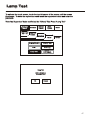
Lamp Test
To activate the touch screen, touch the top left corner of the screen until the screen
illuminates. To enter the supervisor mode touch the supervisor button and enter the
passcode.
Enter the Supervisor Mode and Select the “Others” Tab. Press “Lamp Test”
Supervisor
FRE off
Silence
Alarms
Evacuate
Mute
Buzzer
Reset
Faults
Others
View Fires
AC = 19 View Pre
Alarms
Disabled
Enable/Disable
Weekly Test
Print
View Log
Lamp Test
Check
Auto Config.
Lamp Test
LED’s will light in
numerical order
Ok
Cancel
47
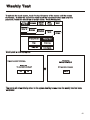
Weekly Test
To activate the touch screen, touch the top left corner of the screen until the screen
illuminates. To enter the supervisor mode touch the supervisor button and enter the
passcode. Select the others tab as shown below. Press Weekly test.
Supervisor
FRE off
View Fires
AC = 19
Silence
Alarms
Evacuate
Pre
Alarms
Disabled
Mute
Buzzer
Faults
Enable/Disable
Weekly Test
Print
View Log
Lamp test
Reset
Others
Check
Auto Config.
Weekly test is now in progress.
Weekly test
Awaiting Alarm Signal
Feature is outside EN54 Spec
Weekly test
Do you want to continue?
Yes
No
Will reset after 4 minutes
Cancel
The panel will automatically return to the system healthy screen once the weekly test has been
completed.
48
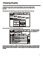
Viewing Events
To activate the touch screen, touch the top left corner of the screen until the screen
illuminates. To enter the supervisor mode touch the supervisor button and enter the
passcode.
Enter the Supervisor Mode Passcode. Select the “Others” tab and press View Log.
Supervisor
FRE off
View Fires
AC = 19
Evacuate
Pre
Alarms
Mute
Buzzer
Silence
Alarms
Disabled
Faults
Enable/Disable
Weekly Test
Print
View Log
Lamp Test
Check
Auto Config.
Reset
Others
Use the scroll bar to view the list of upto 1000 events.
Supervisor
FRE off
Evacuate
Silence
Alarms
Newest
Oldest
Exit
Show
All
Show
Fires
Show
Faults
Mute
Buzzer
Reset
Events can be sorted
by selecting from the
sort option menu.
Show
Tests
001 Monday 13-Jan-2004 08:34:12
Hard Reset
002 FIRE! Lobby, [Optical] (Ana=150)
Building 1, Ground floor, Panel 1, Loop 1, device 1
003 Monday 06-Nov- 2000 11:22.56
Soft Reset
004 Monday 13-Nov-2001, 18:09.07 Fault
Panel1, Loop 2 Zone 2, Address 5
005 Monday 18-Feb-2001 22:20.18
Mains or Battery failure
The Panel event log stores up to 1000 events including, fires, faults, resets and address changes.
Once the maximum 1000 events has been reached Panel will automatically overwrite the oldest
event every time a new event is stored. The event log can only be reset by an approved service
engineer.
49
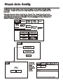
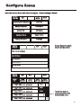
Check Auto Config
To activate the touch screen, touch the top left corner of the screen until the screen
illuminates. To enter the supervisor mode touch the supervisor button and enter the
passcode.
Enter the Supervisor Mode and Select the “Others” Tab. Press Check Auto Config.
This feature will scan the loop and pinpoint the exact location of any break in the loop
wiring and will also identify any changes in the loop configuration (e.g. New devices
added or changed device types).
Supervisor
FRE off
Fires
AC = 0
Silence
Alarms
Evacuate
Mute
Buzzer
Reset
Faults
Others
View Pre
Alarms
Disabled
Enable/Disable
Weekly Test
Print
View Log
Check
Auto Config.
Lamp test
Supervisor
FRE Off
Check Auto Config
Replace Device
Exit
Supervisor
FRE Off
Check
Auto Config
Yes
No
Press the
Supervisor
Mode
button at
the top left
of the
screen.
Supervisor
Evacuate
FRE Off
Print
Silence
Alarms
Mute
Buzzer
Reset
Exit
None Found
Any device listed above is not correctly configured
50
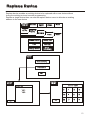
Replace Device
Replace device enables an existing device to be replaced with a new device without
losing the existing text and sounder programming.
Replace a single device then use use the replace device menu to allocate an existing
address to the new device
Supervisor
FRE off
Fires
AC = 0
Evacuate
Silence
Alarms
Mute
Buzzer
Reset
Faults
Others
View Pre
Alarms
Disabled
Enable/Disable
Weekly Test
Print
View Log
Change Device
Check
Auto Config.
Supervisor
FRE Off
Check Auto Config
Replace Device
Exit
Supervisor
FRE Off
Supervisor
FRE Off
Enter Loop 1 Address
Select a Loop
Loop 1
0
1
2
3
Del
4
5
6
Ok
7
8
9
Loop 2
Exit
Exit
51
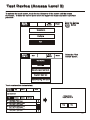
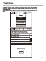
Test Device (Access Level 3)
To activate the touch screen, touch the top left corner of the screen until the screen
illuminates. To enter the service mode touch the supervisor button and enter supervisor
passcode.
Service
FRE Off
Mute
Buzzer
Reset
Mute
Buzzer
Reset
Enter the Service
mode. Select
“Test”.
Commission
Configure
Test
Service
FRE Off
Exit
Select the “Test
Device” button.
Test Device
Test Zone
Sounder Level Test Mode
One Man Walk Test
Global Flashing LED on/off
Touch row to select device to test.
Service
FRE Off
Exit
Reset
Go to
Touch row to test
Show
All
Show
Detectors
Show
Alarms
Show
I/O Units
Testing Device
Testing Address: A
001 Lobby, Build 1, 1st floor
Loop: 1, Zone: 2, Type: Optical
002 Main Reception, Building 1, 1st floor
Loop: 1, Zone: 2, Type: Optical
Stop
Stop
003 Storage/archive, Building 1, 1st floor
Loop: 1, Zone: 2, Type: Optical
004 Meeting Room 1, Building 1, 1st floor
Loop: 1, Zone: 2, Type: Optical
52
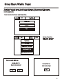
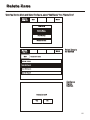
Test Zone
To activate the touch screen, touch the top left corner of the screen until the screen
illuminates. To enter the supervisor mode touch the supervisor button and enter the
service passcode.
Enter the Service Mode, Select “Test” and on the Screen Shown Below Press “Test
Zone”
Service
FRE Off
Mute
Buzzer
Exit
Reset
Test Device
Test Zone
Sounder Level Test Mode
One Man Walk Test
Global Flashing LED on/off
Service
FRE Off
Reset
Exit
Touch "-" Button to place a zone into test mode
Touch "-" Button to remove a zone from test mode
Zone 001 Building 1, Ground
Zone 002 Building 1, 1st floor
Zone 003 Building 1, 2nd floor
Zone 004 Packing & Stores
Zone 005 Building 2, basement
Testing Zone: Scanning
Stop
53
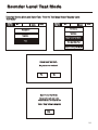
Sounder Level Test Mode
Enter the Service Mode and Select Test. From the Test Menu Select “Sounder Level
Test Mode”
Service
FRE Off
Mute
Buzzer
Exit
Service
FRE Off
Reset
Mute
Buzzer
Exit
Reset
Test Device
Commission
Test Zone
Configure
Sound Level Test Mode
Test
One Man Walk Test
Global Flashing LED On/Off
Sound Level Test Mode
Do you want to continue?
No
Yes
Sound Level Test Mode
All sounders will now pulse
15 seconds on, 30 seconds off
Touch “Stop” button to stop test
Stop
54
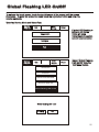
Global Flashing LED On/Off
To activate the touch screen, touch the top left corner of the screen until the screen
illuminates. To enter the supervisor mode touch the supervisor button and enter the
service passcode.
Enter the Service Mode and Select Test.
Service
FRE Off
Exit
Mute
Buzzer
Reset
Mute
Buzzer
Reset
If global LED flashing is
set to on, all device
LED’s will pulse
intermittently to confirm
correct communication.
Commission
Configure
Test
Service
FRE Off
Exit
Select “Global Flashing
LED On/Off” from the
Test Menu Screen.
Test Device
Test Zone
Sound Level Test Mode
One Man Walk Test
Global Flashing LED On/Off
Global flashing LED on/of
Flashing
Off
55
One Man Walk Test
To activate the touch screen, touch the top left corner of the screen until the screen
illuminates. To enter the supervisor mode touch the supervisor button and enter the
service passcode.
Enter the Service Mode and Select Test.
Service
FRE Off
Mute
Buzzer
Exit
Commission
Configure
Test
Service
FRE Off
Mute
Buzzer
Exit
Reset
Select “One Man
Walk Test” from the
Test Menu Screen.
Test Device
Test Zone
Sound Level Test Mode
One Man Walk Test
Global Flashing LED On/Off
Feature is outside EN54 spec
One Man Walk Test
One Man Walk Test
Do you want to continue?
Awaiting Alarm Signal
Yes
No
Stop
56
Commission: Load CDR from Laptop
To activate the touch screen, touch the top left corner of the screen until the screen
illuminates. To enter the supervisor mode touch the supervisor button and enter the
service passcode.
Enter the Service Mode and Select Commission..
Service
Mute
Buzzer
Exit
Reset
Commission
Configure
Test
Service
FRE Off
Mute
Buzzer
Exit
Load CDR from Laptop
Reset
Analogue Level
Download CDR to Laptop
Printer Settings
Auto Learn
Change Panel Number
Erase Log and Reset
Number of Panels
in Network
System Detail
Screen Cover
Load logo from PC
Select “Load CDR from
Laptop” from the
Commission Menu”
Italian Mode
After pressing “Yes” click
commission on the PC
download software.
Load CDR from Laptop
This will erase the current CDR
Do you want to continue?
Yes
Important:
Do not click commission
before pressing “Yes” on the
“Load CDR” screen.
No
57
Commission: Download CDR to Laptop
To activate the touch screen, touch the top left corner of the screen until the screen
illuminates. To enter the supervisor mode touch the supervisor button and enter the
service passcode.
Enter the Service Mode and Select Commission.
Service
Exit
Mute
Buzzer
Reset
Mute
Buzzer
Reset
Commission
Configure
Test
Service
FRE Off
Exit
Load CDR from Laptop
Analogue Level
Download CDR to Laptop
Printer Settings
Auto Learn
Change Panel Number
Erase Log and Reset
Number of Panels
in Network
System Detail
Screen Cover
Load logo from PC
Select “Download CDR
from Laptop” from the
Commission Menu
Screen.
Italian Mode
Download CDR to Laptop
Start PC program
Press "OK" to continue
or "Cancel" to exit
OK
Cancel
58
Commission: Auto Learn
To activate the touch screen, touch the top left corner of the screen until the screen
illuminates. To enter the supervisor mode touch the supervisor button and enter the
service passcode.
Enter the Service Mode and Select Commission.
Service
FRE off
Mute
Buzzer
Exit
Reset
Commission
Configure
Test
Service
FRE Off
Mute
Buzzer
Exit
Load CDR from Laptop
Reset
Analogue Level
Download CDR to Laptop
Printer Settings
Auto Learn
Change Panel Number
Erase Log and Reset
Number of Panels
in Network
System Detail
Screen Cover
Load logo from PC
Select “Auto Learn” from
the Configure Menu
Screen.
Italian Mode
Important:
Auto Learn
This will erase the current CDR
Do you want to continue
Yes
Activating autolearn will
erase all existing
programming, text and
configuration data.
No
59
Erase Log
To activate the touch screen, touch the top left corner of the screen until the screen
illuminates. To enter the supervisor mode touch the supervisor button and enter the
service passcode.
Enter the Service Mode and Select Commission.
Service
FRE off
Exit
Mute
Buzzer
Reset
Mute
Buzzer
Reset
Commission
Configure
Test
Service
FRE Off
Exit
Load CDR from Laptop
Analogue Level
Download CDR to Laptop
Printer Settings
Auto Learn
Change Panel Number
Erase Log and Reset
Number of Panels
in Network
System Detail
Screen Cover
Load logo from PC
Select “Erase Log
and Reset” from the
Configure Menu
Screen.
Italian Mode
This will delete all log entries
Do you want to continue
Yes
No
60
System Details
To activate the touch screen, touch the top left corner of the screen until the screen
illuminates. To enter the supervisor mode touch the supervisor button and enter the
service passcode.
Enter the Service Mode and Select Commission, then Press “System Details”.
Service
FRE off
Mute
Buzzer
Exit
Service
FRE Off
Reset
Mute
Buzzer
Exit
Load CDR from Laptop
Reset
Analogue Level
Commission
Download CDR to Laptop
Printer Settings
Auto Learn
Change Panel Number
Erase Log and Reset
Number of Panels
in Network
System Detail
Screen Cover
Configure
Test
Italian Mode
Load logo from PC
Service
FRE off
Print
Program
Program Data
Program Checksum
CDR
CDR Checksum
Loop Controller 1
Loop Controller 2
Panel Number
Total Panels
Total Addresses
Total Zones
Page 1
Service
FRE off
Reset
Exit
V0.00.15
09-Mar-2004
0xAA95524
V0.5
0xF7D95E
V0.0.0
V0.0.0
0
1
13
4
Page 2
Print
Service
FRE off
Loop 2
0
13
0
0
0
2
0
0
0
0
14
0
0
0
1
0
0
0
Page 1
Print
Sounder Control Unit
Voice Annunciator
Repeater
ZMU/{SUM
Beam Detector
Filtrex
Access Control
Emerg.Light.Module
Carbon Monoxide
Page 1
0
13
0
0
0
2
0
0
0
Page 2
Loop 3
0
0
0
0
0
0
0
0
0
Loop 4
0
0
0
0
0
0
0
0
0
Page 3
Reset
Exit
Loop 1
Reset
Loop 1
Optical
Ionisation
Thermal A1R
Opto/Thermal
Thermal BS
Thermal CS
Call Point
Alarm
I/O Units
Page 3
Exit
Loop 2
Loop 3
0
14
0
0
0
1
0
0
0
0
0
0
0
0
0
0
0
0
Page 2
Loop 4
0
0
0
0
0
0
0
0
0
Page 3
61
Load Logo from PC
To activate the touch screen, touch the top left corner of the screen until the screen
illuminates. To enter the supervisor mode touch the supervisor button and enter the
service passcode.
Enter the Service Mode and Select Commission.
Service
FRE off
Exit
Mute
Buzzer
Reset
Mute
Buzzer
Reset
Commission
Configure
Test
Service
FRE Off
Exit
Load CDR from Laptop
Analogue Level
Download CDR to Laptop
Printer Settings
Auto Learn
Change Panel Number
Erase Log and Reset
Number of Panels
in Network
System Detail
Screen Cover
Select “Load logo
from PC” from the
Configure Menu
Screen.
Italian Mode
Load logo from PC
Load logo from PC
Exit
62
Analogue Level
To activate the touch screen, touch the top left corner of the screen until the screen
illuminates. To enter the supervisor mode touch the supervisor button and enter the
service passcode.
Enter the Service Mode and Select Commission then press “Analogue Levels”.
Service
FRE Off
Mute
Buzzer
Exit
Service
FRE Off
Reset
Mute
Buzzer
Exit
Load CDR from Laptop
Reset
Analogue Level
Commission
Download CDR to Laptop
Printer Settings
Auto Learn
Change Panel Number
Erase Log and Reset
Number of Panels
in Network
System Detail
Screen Cover
Configure
Test
Load logo from PC
Service
FRE off
Exit
Goto
Show
All
Show
Detectors
Show
Optical
Italian Mode
Reset
Show
Show
Ionisation Thermal
001 Device 1, Zone 1
Loop: 1, Zone: 1, Type: Opto/thermal
002 Device 2, Zone 1
Loop: 1, Zone: 1, Type: Opto/thermal
Note
Go to
command can
be used to
jump to a
specific
address
003 Device 3, Zone 1
Loop: 1, Zone: 1, Type: Opto/thermal
004 Device 4, Zone 1
Loop: 1, Zone: 1, Type: Opto/thermal
005 Device 5, Zone 1
Loop: 1, Zone: 1, Type: Opto/thermal
Enter Address
..................
Loop 1
0 - 13
Loop 2
0-0
Loop 3
0-0
Loop 4
0-0
Cancel
1
4
7
ok
2 3
5 6
8 9
0
63
Printer Settings
To activate the touch screen, touch the top left corner of the screen until the screen
illuminates. To enter the supervisor mode touch the supervisor button and enter the
service passcode.
Enter the Service Mode and Select Commission then press “Printer settings”.
Service
FRE Off
Exit
Mute
Buzzer
Reset
Mute
Buzzer
Reset
Commission
Configure
Test
Service
FRE Off
Exit
Load CDR from Laptop
Analogue Level
Download CDR to Laptop
Printer Settings
Auto Learn
Change Panel Number
Erase Log and Reset
Number of Panels
in Network
System Detail
Screen Cover
Italian Mode
Load logo from PC
Service
FRE off
Reset
Exit
Auto
Request
64
Change Panel Number
To activate the touch screen, touch the top left corner of the screen until the screen
illuminates. To enter the supervisor mode touch the supervisor button and enter the
service passcode.
Enter the Service Mode and Select Commission then press “Change Panel Number”
Service
FRE Off
Exit
Mute
Buzzer
Reset
Mute
Buzzer
Reset
Commission
Configure
Test
Service
FRE Off
Exit
Load CDR from Laptop
Analogue Level
Download CDR to Laptop
Printer Settings
Auto Learn
Change Panel Number
Erase Log and Reset
Number of Panels
in Network
System Detail
Screen Cover
Italian Mode
Load logo from PC
Change Panel Number
0
..............................
Cancel
1
4
7
ok
2 3
5 6
8 9
0
65
Number of Panels in Network
To activate the touch screen, touch the top left corner of the screen until the screen
illuminates. To enter the supervisor mode touch the supervisor button and enter the
service passcode.
Enter the Service Mode and Select Commission then press “Number of Panels in
Service
FRE Off
Exit
Mute
Buzzer
Reset
Mute
Buzzer
Reset
Commission
Configure
Test
Service
FRE Off
Exit
Load CDR from Laptop
Analogue Level
Download CDR to Laptop
Printer Settings
Auto Learn
Change Panel Number
Erase Log and Reset
Number of Panels
in Network
System Detail
Screen Cover
Italian Mode
Load logo from PC
Number of Panels
in Network
1
..............................
Cancel
1
4
7
ok
2 3
5 6
8 9
0
66
Screen Cover
To activate the touch screen, touch the top left corner of the screen until the screen
illuminates. To enter the supervisor mode touch the supervisor button and enter the
service passcode.
Enter the Service Mode and Select Commission then press “Screen Cover”
Service
FRE Off
Exit
Mute
Buzzer
Reset
Mute
Buzzer
Reset
Commission
Configure
Test
Service
FRE Off
Exit
Load CDR from Laptop
Analogue Level
Download CDR to Laptop
Printer Settings
Auto Learn
Change Panel Number
Erase Log and Reset
Number of Panels
in Network
System Detail
Screen Cover
Load logo from PC
Service
FRE off
Italian Mode
Reset
Exit
Installed
Not Required
67
Italian Mode
To activate the touch screen, touch the top left corner of the screen until the screen
illuminates. To enter the supervisor mode touch the supervisor button and enter the
service passcode.
Enter the Service Mode and Select Commission then press “Italian Mode”.
Service
FRE Off
Exit
Mute
Buzzer
Reset
Mute
Buzzer
Reset
Commission
Configure
Test
Service
FRE Off
Exit
Load CDR from Laptop
Analogue Level
Download CDR to Laptop
Printer Settings
Auto Learn
Change Panel Number
Erase Log and Reset
Number of Panels
in Network
System Detail
Screen Cover
Load logo from PC
Service
FRE off
Italian Mode
Reset
Exit
T1:Call Point Delay
0 mins,0 secs
T2:Detector Delay
0 mins
Enabled
Disabled
68
Programming I/O and Sounders T1
To activate the touch screen, touch the top left corner of the screen until the screen
illuminates. To enter the supervisor mode touch the supervisor button and enter the
service passcode.
Enter the Service Mode and Select Configure.
Service
FRE off
Mute
Buzzer
Exit
Reset
Commission
Configure
Test
Select “Programming
I/O and Sounders”
from the Configure
Menu Screen.Then
press T1
Service
FRE off
Mute
Buzzer
Exit
Programming I/O
and Sounders
Service
FRE off
Reset
Mute
Buzzer
Exit
T1
Add/Delete
Change Date/Time
T2
Configure Heat Detectors
Change Text
Network
Panel Outputs
Configure Zones
Language
Auxiliary Board
Alarm Verification Features
Day/Night
Change Pascode
Reset
T1
Off
10 secs
20 secs
30 secs
40 secs
50 secs
60 secs
70 secs
80 secs
90 secs 100 secs 110 secs 120 secs
130 secs 140 secs 150 secs 160 secs 170 secs 180 secs
Exit
69
Programming I/O and Sounders T2
To activate the touch screen, touch the top left corner of the screen until the screen
illuminates. To enter the supervisor mode touch the supervisor button and enter the
service passcode.
Enter the Service Mode and Select Configure.
Service
FRE off
Mute
Buzzer
Exit
Reset
Commission
Configure
Test
Select “Programming
I/O and Sounders”
from the Configure
Menu Screen.Then
press T2
Service
FRE off
Mute
Buzzer
Exit
Programming I/O
and Sounders
Change Date/Time
Service
FRE off
Reset
Mute
Buzzer
Exit
T1
Add/Delete
T2
Configure Heat Detectors
Change Text
Network
Panel Outputs
Configure Zones
Language
Auxiliary Board
Alarm Verification Features
Day/Night
Change Pascode
Reset
T2
Off
1 min
2 min
3 min
4 min
5 min
6 min
7 min
8 min
9 min
10 min
Exit
70
Programming I/O and Sounders . Panel Outputs
To activate the touch screen, touch the top left corner of the screen until the screen
illuminates. To enter the supervisor mode touch the supervisor button and enter the
service passcode.
Enter the Service Mode and Select Configure.
Service
FRE off
Exit
Mute
Buzzer
Reset
Mute
Buzzer
Reset
Commission
Configure
Test
Service
FRE off
Exit
Add/Delete
Programming I/O and Sounders
Configure Heat Detectors
Change Date/Time
Change Text
Network
Configure Zones
Language
Day/Night
Change User Code
Service
FRE off
Select “Programming
I/O and Sounders”
from the Configure
Menu Screen.
Mute
Buzzer
Exit
T1
T2
Reset
Press panel outputs NOTE Interface
Inputs/Interface
Outputs are only used
in certain export
markets
Panel Outputs
Auxiliary Board
Alarm Verification Features
71
Programming I/O and Sounders . Auxiliary Board
To activate the touch screen, touch the top left corner of the screen until the screen
illuminates. To enter the supervisor mode touch the supervisor button and enter the
service passcode.
Enter the Service Mode and Select Configure.
Service
FRE off
Mute
Buzzer
Exit
Reset
Commission
Configure
Test
Select “Programming
I/O and Sounders”
from the Configure
Menu Screen.Then
press Auxiliary Board
Service
FRE off
Exit
Programming I/O
and Sounders
Change Date/Time
Mute
Buzzer
Reset
Service
FRE off
Mute
Buzzer
Exit
T1
Add/Delete
Configure Heat Detectors
T2
Change Text
Network
Panel Outputs
Configure Zones
Language
Auxiliary Board
Change Pascode
Reset
Alarm Verification Features
Day/Night
Not Required
Vds Extinguisher
Vds Fire Bridgsde
Australian
Swedish Mode
72
Programming I/O and Sounders Alarm Verification
To activate the touch screen, touch the top left corner of the screen until the screen
illuminates. To enter the supervisor mode touch the supervisor button and enter the
service passcode.
Enter the Service Mode and Select Configure.
Service
FRE off
Mute
Buzzer
Exit
Reset
Commission
Configure
Test
Select “Programming
I/O and Sounders”
from the Configure
Menu Screen.Then
press Alarm Verification
Service
FRE off
Exit
Programming I/O
and Sounders
Change Date/Time
Mute
Buzzer
Service
FRE off
Reset
Mute
Buzzer
Exit
T1
Add/Delete
T2
Configure Heat Detectors
Change Text
Network
Panel Outputs
Configure Zones
Language
Auxiliary Board
Change Pascode
Reset
Alarm Verification Features
Day/Night
Alarm verification feature
Activate AVF?
Disabled
Enabled
Exit
73
Sound Settings
Touch sound settings .
Service
FRE off
Exit
Reset
Sound Settings
Selections from the screens below will become the global settings for all loop sounders.
Service
FRE off
Exit
Reset
Service
FRE off
Exit
Reset
Low
Volume
Medium
High
Sound
Service
FRE off
Exit
Reset
Volume
Service
FRE off
Exit
Reset
Slow Woop
Two Tone
Sound
Continuous
74
Change Date/Time
Enter the Service Mode and Select Configure. Select Change Date/Time.
Service
FRE Off
Mute
Buzzer
Exit
Reset
Programming I/O and Sounders
Add Zone
Change Date/Time
Delete Zone
Change Text
Add Device
Configure Zones
Delete Device
Day/Night
Change Password
Set the Time Using the Buttons Shown Below.
Service
FRE Off
Ok
Current Time:
10:16:12
Cancel
Reset
+1
Hour
+10
Mins
+1
Mins
-1
Hour
-10
Mins
-1
Mins
+1
Day
+1
Month
+1
Year
-1
Day
-1
Month
-1
Year
BST On
Current Date:
Wednesday
dd-mmm-yyyy
75
Change Zone Text
Enter the Service Mode and Select Configure. Select “Change Text”
Service
FRE Off
Mute
Buzzer
Exit
Reset
Programming I/O and Sounders
Add Zone
Change Date/Time
Delete Zone
Change Text
Add Device
Configure Zones
Delete Device
Change Password
Service
FRE Off
Day/Night
Mute
Buzzer
Exit
Press “Change
Zone Text”
Reset
Change address text
Change zone text
Change Panel Text
Select the zone you wish to Change and Edit Using the Keyboard
Service
FRE Off
Reset
Enter the name for Zone 2
Exit
Zone 2
.......................................................................................
Zone 001 Zone 1
Zone 002 Zone 2
Zone 003 Zone 3
Zone 004 Zone 4
1
2
3
4
5
6
7
8
9
0
Q
W
E
R
T
Y
U
I
O
P
A
CAPS
S
Z
OTHER
D
X
F
C
G
V
SPACE
H
B
J
N
K
M
OK
L
,
.
CANCEL
76
Change Text
Enter the Service Mode and Select Configure. Select “Change Text”
Service
FRE Off
Mute
Buzzer
Exit
Reset
Programming I/O and Sounders
Add Zone
Change Date/Time
Delete Zone
Change Text
Add Device
Configure Zones
Delete Device
Change Password
Day/Night
Press “Change Address Text”
Service
FRE Off
Mute
Buzzer
Exit
Reset
Change address text
Change zone text
Change Panel Text
Select the Address you wish to change and edit using the keyboard
Service
FRE Off
Exit
Go To
Show
All
Show
Detectors
Show
Alarms
Reset
Name for address 1
Address1
...........................................................................
Show
I/O Units
001 Device 1, Zone 1
Loop: 1, Zone: 1, Type : Opto/thermal
1
2
3
4
5
6
7
8
9
0
002 Device 2, Zone 1
Loop: 1, Zone: 1, Type : Opto/thermal
Q
W
E
R
T
Y
U
I
O
P
003 Device 3, Zone 1
Loop: 1, Zone: 1, Type : Opto/thermal
004 Device 4, Zone 1
Loop: 1, Zone: 1, Type : Opto/thermal
005 Device 5, Zone 1
Loop: 1, Zone: 1, Type : Opto/thermal
A
CAPS
S
Z
OTHER
D
X
F
C
G
V
SPACE
H
B
J
N
K
M
OK
L
,
.
CANCEL
77
Change Panel Text
Enter the Service Mode and Select Configure. Select “Change Text”
Service
FRE Off
Mute
Buzzer
Exit
Reset
Programming I/O and Sounders
Add Zone
Change Date/Time
Delete Zone
Change Text
Add Device
Configure Zones
Delete Device
Change Password
Day/Night
Service
FRE Off
Exit
Press “Change
Panel Text”
Reset
Change address text
Change zone text
Change Panel Text
Correct Panel Text
CF1100
.......................................................................................
1
2
3
4
5
6
7
8
9
0
Q
W
E
R
T
Y
U
I
O
P
A
CAPS
S
Z
OTHER
D
X
F
C
G
V
SPACE
H
B
J
N
K
M
OK
L
,
.
CANCEL
78
Configure Zones
Enter the Service Mode and Select Configure. Select “Configure Zones”
Service
FRE Off
Mute
Buzzer
Exit
Reset
Programming I/O and Sounders
Add Zone
Change Date/Time
Delete Zone
Change Text
Add Device
Configure Zones
Delete Device
Change Password
Day/Night
Service
FRE Off
Reset
Exit
Select Zone into which
device will be added
Touch row to configure
Zone 001 Zone 1
Zone 002 Zone 2
Zone 003 Zone 3
Zone 004 Zone 4
Service
FRE Off
Exit
Goto
Show
All
Show
Detectors
Show
Alarms
Reset
Show
Selected
Show
I/O Units
001 Device 1, Zone 1
Loop: 1, Zone: 1, Type : Opto/thermal
In Zone
002 Device 2, Zone 1
Loop: 1, Zone: 1, Type : Opto/thermal
In Zone
003 Device 3, Zone 1
Loop: 1, Zone: 1, Type : Opto/thermal
In Zone
004 Device 4, Zone 2
Loop: 1, Zone: 2, Type : Opto/thermal
-
005 Device 5, Zone2
Loop: 1, Zone: 2, Type : Opto/thermal
-
Touch the dash to
move the device into
the selected zone.
79
Change Passcode
Enter the Service Mode and Select Configure. Select “Change User Code”
Service
FRE off
Mute
Buzzer
Exit
Add/Delete
Programming I/O and Sounders
Change Date/Time
Configure Heat Detectors
Change Text
Network
Configure Zones
Language
Day/Night
Change Password
Please enter Passcode:
..............................
New Code:
..............................
Verify New Code:
..............................
Cancel
Reset
1
4
7
ok
2 3
5 6
8 9
0
Passcode is not correct.
No change made
Verification is incorrect
No change made
New Password accepted
Saved
Ok
Ok
Ok
80
Add Zone
Enter the Service Mode and Select Configure. Select “Add Zone”
Service
FRE off
Mute
Buzzer
Exit
Reset
Programming I/O and Sounders
Add/Delete
Change Date/Time
Configure Heat Detectors
Change Text
Network
Configure Zones
Language
Day/Night
Change Password
Service
FRE Off
Reset
Exit
Add Zone
Delete Zone
Add Device
Delete Device
Add Zone ?
Yes
No
81
Delete Zone
Enter the Service Mode and Select Configure, select “Add/Delete” then “Delete Zone”
Service
FRE Off
Reset
Exit
Add Zone
Delete Zone
Add Device
Delete Device
Service
FRE Off
Exit
Reset
Select Zone to
be Deleted
Touch row to delete
Zone 001 Zone 1
Zone 002 Zone 2
Zone 003 Zone 3
Zone 004 Zone 4
Confirm or
Cancel
Deletion
Delete Zone 2?
Yes
No
82
Add Device
Enter the Service Mode and Select Configure, select “Add/Delete” then “Add Device”
Service
FRE Off
Reset
Exit
Add Zone
Delete Zone
Add Device
Delete Device
Service
FRE Off
Reset
Select a Loop
to Add a New
Device
Loop 1
Loop 2
Exit
Confirm
New
Device
and Loop
Loop 2
Scanning Loop
Exit
83
Delete Device
Enter the Service Mode and Select Configure, select “Add/Delete” then “Delete Device”
Service
FRE Off
Reset
Exit
Add Zone
Delete Zone
Add Device
Delete Device
Service
FRE Off
Exit
Reset
Goto
Select a
Device to
Delete
Touch row to delete
001 Device 1, Zone 1
Loop: 1, Zone: 1, Type : Opto/thermal
002 Device 2, Zone 2
Loop: 1, Zone: 2, Type : Opto/thermal
003 Device 3, Zone 1
Loop: 1, Zone: 2, Type : Opto/thermal
004 Device 4, Zone 2
Loop: 1, Zone: 2, Type : Opto/thermal
005 Device 5, Zone 1
Loop: 1, Zone: 1, Type : Opto/thermal
Confirm or
Cancel
Deletion
Delete Device 3?
Device 3
Loop 1, Address 3, Device Type Opto/thermal
Yes
No
84
Configure Heat Detectors
Enter the Service Mode and Select Configure. Select “Configure Heat Detectors”
Service
FRE off
Mute
Buzzer
Exit
Reset
Programming I/O and Sounders
Add/Delete
Change Date/Time
Configure Heat Detectors
Change Text
Network
Configure Zones
Language
Day/Night
Change Password
Service
FRE Off
Reset
Exit
Select a
Device to
Configure
Touch row to configure
001 Device 1, Zone 1
Loop: 1, Zone: 1, Type : Opto/thermal
002 Device 2, Zone 2
Loop: 1, Zone: 2, Type : Opto/thermal
003 Device 3, Zone 1
Loop: 1, Zone: 2, Type : Opto/thermal
004 Device 4, Zone 2
Loop: 1, Zone: 2, Type : Opto/thermal
005 Device 5, Zone 1
Loop: 1, Zone: 1, Type : Opto/thermal
Select appropriate detector class
Service
FRE Off
Exit
Reset
Thermal A1R
Thermal BS
Thermal CS
Exit
85
Network
Enter the Service Mode and Select Configure. Select “Network”, This menu defines
whether messages are broadcast across the network or remain local.
Service
FRE off
Mute
Buzzer
Exit
Reset
Programming I/O and Sounders
Add/Delete
Change Date/Time
Configure Heat Detectors
Change Text
Network
Configure Zones
Language
Day/Night
Change Password
Select the specific required . E.g “Reset”
Service
FRE Off
Receive message over network
Reset
Network
Evacuate
Network
Silence
Network
Fire
Network
Fault
Network
Pre-Alarm
Network
Select if Network is required to be on/off
Service
FRE Off
Reset
Not Required
86
Language
To activate the touch screen, touch the top left corner of the screen until the screen
illuminates. To enter the supervisor mode touch the supervisor button and enter the
service passcode.
Enter the Service Mode and Select Configure.
Service
FRE off
Mute
Buzzer
Exit
Reset
Commission
Configure
Test
Service
FRE off
Mute
Buzzer
Exit
Programming I/O
and Sounders
Change Date/Time
Add/Delete
Configure Heat Detectors
Change Text
Network
Configure Zones
Language
Day/Night
Change Pascode
Service
FRE off
Reset
Select “Programming
I/O and Sounders”
from the Configure
Menu Screen.Then
press Language
Mute
Buzzer
Exit
Select required
Language
Reset
English
French
German
Dutch
Italian
Portuguese
Flemish
Chinese
Czech
Danish
Slovakian
Hungarian
Slovenian
87
Day / Night
To activate the touch screen, touch the top left corner of the screen until the screen
illuminates. To enter the supervisor mode touch the supervisor button and enter the
service passcode.
Enter the Service Mode and Select Configure.
Service
FRE off
Mute
Buzzer
Exit
Reset
Commission
Configure
Test
Select “Day/Night”
from the Configure
Menu Screen.
Service
FRE off
Mute
Buzzer
Exit
Programming I/O
and Sounders
Reset
Add/Delete
Configure Heat Detectors
Change Date/Time
Change Text
Network
Configure Zones
Language
Day/Night
Change Pascode
Delay (minutes)
Off
1
2
3
4
5
6
7
8
9
10
Exit
Feature is outside En54 spec
88
Password Protection
Please enter Passcode
1
4
7
ok
2 3
5 6
8 9
0
The system has password protection which restricts access to the DISABLE Menu and
to TEST/COMMISSIONING MODE. The password is a four digit code and the default
number is 2214. The password entry screen is accessed via the supervisor mode
button. Press supervisor mode and the password entry screen will be displayed, type in
the passcode and press Ok. If the wrong password is entered three times further access
to the system is denied.
89
Section 4
Appendix
90
System Wiring
L
E
+
1 -
+
+
2 -
2 -
SOUNDER CIRCUIT
1 -
NO
C
AUX
RELAY
NC
-
Any 800 Series Analogue Detector
can be Connected to the Loop
+
FAULT
RELAY
Tx+ Tx-
RS485
0V +26V
-
FIRE R/E
+
-
+
FIRE P/E
CLASS
CHANGE
F+
LOOP1
S+
F-
S-
LOOP1
E
E
N
MAINS
+
NETWORK CIRCUIT
E
E
EARTH
E
EARTH
EARTH
EARTH
EARTH
F-
LOOP2
F+
S-
LOOP2
S+
91
Security House,
Vantage Point Business Village,
Mitcheldean,
Glos. GL17 0SZ
Tel: 01594 541900
www.cooperfire.co.uk
Installation:
Wiring
Each unit terminal connector is suitable for clamping a
single cable conductor up to a maximum of 2.5mm².
The CSI350 unit is suitable for mounting on to back boxes
with 120mm fixing centres. (surface mounting box supplied)
1
2
3
4
5
6
Separate the two halves of the unit
Drill out the required holes for cable entries
Mount the back box in the required position
Install wiring through the pre-drilled holes
Connect the unit as per diagram below
Fit front cover
Installation Guide for
Spur Isolator Unit
CSI350
CSI350 - Specification:
Quiescent Current:
Operating Temperature:
Humidity:
IP Rating:
Standards:
EMC:
Materials:
Dimensions:
Cable Size (Min-Max:)
Recommended Cable Types:
170µA
-10 to +60C
0 to 95% non condensing
IP40
EN54:Pt 2 and 4
BS5839:Pt 1 (installation)
CE Marked
PC\ABS
147(w)x88(h)x57(d) mm
0.5 to 2.5mm²
Draka - FIRETUF
Pirelli - FP200
MICC
General
Addressing of the unit is not required (see control panel
operation for details)
Wiring Schematic:
Notes:
1. Cable earth screen must be connected to its adjacent earth terminal.
2. For maximum spur length/load see BS5839 Pt1:2002
3. This unit can only be used with Cooper Fire Systems CAB300 sensor bases and compatible sensors
DOC. REF.: PINSTCSI350
92
Security House,
Vantage Point Business Village,
Mitcheldean,
Glos. GL17 0SZ
Tel: 01594 541900
www.cooperfire.co.uk
Installation Guide for
4 Way Sounder Controller Unit
CSC354
Installation:
Wiring
Each unit terminal connector is suitable for clamping a
single cable conductor up to a maximum of 2.5mm².
1
2
3
4
5
Remove the front cover of the unit
Mount the back box in the required position.
Install wiring through the pre-drilled holes ensuring
care is taken not to damage the circuit board.
Connect the unit as per diagram below.
Refit front cover.
General
The CSC354 unit requires a permanent 230Vac supply.
Addressing of the unit is not required (see control panel
operation for details)
CSC354 - Specification:
Mains supply voltage:
Mains current consumption:
Operating voltage:
Standy period:
Quiescent Current:
Addressing mode:
Sounder circuit output:
Maximum sounder load:
Fire relay switching voltage
Maximum switching current
Operating Temperature:
Humidity:
IP Rating:
Standards:
EMC:
Battery:
Materials:
Dimensions:
Cable Size (Min-Max:)
Recommended Cable Types:
230Vac
0.5A
24Vdc
24hrs + 30 minutes ringing
250µA
Auto addressed
0.8Amp (max)
3.2A (4 channels)
30Vdc
1A (resistive)
0.5A (inductive)
-10 to +45C
0 to 95% non condensing
IP40
EN54:Pt 2 and 4
BS5839:Pt 1 (installation)
CE Marked
2x12V, 4Ah, SLA
PC\ABS\Steel
300(w)x300(h)x74(d) mm
0.5 to 2.5mm²
Draka - FIRETUF
Pirelli - FP200
MICC
Wiring Schematic:
Notes:
1. Cable earth screen must be connected to its adjacent earth terminal.
2. The end of line resistor must always be fitted, even if sounder circuit is not used.
3. Sounder circuits are monitored for wiring open and short circuit.
4. Output fire relay is a set of changeover volt free-contacts and is not monitored.
5. This unit should only be finally connected to the 230Vac mains supply and battery, during
system commissioning
DOC. REF.: PINSTCSC354
93
Security House,
Vantage Point Business Village,
Mitcheldean,
Glos. GL17 0SZ
Tel: 01594 541900
www.cooperfire.co.uk
Installation:
Wiring
Each unit terminal connector is suitable for clamping a
single cable conductor up to a maximum of 2.5mm².
The zone monitor unit is suitable for mounting on to back
boxes with 120mm fixing centres. (surface mounting box
supplied)
1
2
3
4
5
6
Separate the two halves of the unit
Drill out the required holes for cable entries
Mount the back box in the required position
Install wiring through the pre-drilled holes
Connect the unit as per diagram below
Fit front cover
General
Addressing of the unit is not required (see control panel
operation for details)
Installation Guide for
Zone Monitor Unit
CZMU352
CZMU352 - Specification:
Operating voltage:
Quiescent Current:
Current with 20 detectors
Total alarm current
Addressing mode:
Detector zone loading:
Call point load
Operating Temperature:
Humidity:
IP Rating:
Standards:
EMC:
Materials:
Dimensions:
Cable Size (Min-Max:)
Recommended Cable Types:
18 to 30Vdc
2.8mA
3.4mA
8mA
Auto addressed
20 detectors (max)
Unlimired
-10 to +60C
0 to 95% non condensing
IP40
EN54:Pt 2 and 4
BS5839:Pt 1 (installation)
CE Marked
PC\ABS
147(w)x88(h)x57(d) mm
0.5 to 2.5mm²
Draka - FIRETUF
Pirelli - FP200
MICC
Wiring Schematic:
Notes:
1. Cable earth screen must be connected to its adjacent earth terminal.
2. The end of line resistor must always be fitted, even if the spur is not used.
3. Maximum spur length - see BS5839 Pt:1 2002 for zone coverage.
4. There is no maximum number of conventional call points allowed per zone output.
5. This unit can only be used with Cooper Fire Systems CDB300/I detector base and compatible detectors
DOC. REF.: PINSTCZMU352
94
Installation Instructions for:
Shop Unit Monitor CSUM355
Installation
1. Separate the two halves of the unit.
2. Drill out (or knock out) the required cable entries in the surface mounting back-box.
3. Fit the back-box in position and pass the wires into it.
4. Connect the unit according to the diagram below.
Notes:
No addressing of the interface is required. See control panel operation for details.
Standard Connections
24V DC OUTPUT
POWER SUPPLY UNIT
EOLM-1
- OUT +
- IN
Analogue Addressable Loop
-
+
E
OUT
-
IN
LOOP
Maximum 20
Conventional
Detectors
+
24V
O/P
12K
-
+
- OUT +
- IN
E
12K
12K
6K8
Fault
Contact
N/O
+
E
-
CALL
POINT
ZONE
+
+
E
-
+
DETECTOR
ZONE
N/O
C
N/C
FIRE
RELAY
-
+
-
+
-
+
E
-
+
2
1
E
EXTERNAL
PSU
MONITOR
SOUNDER
-
+
24V
EXTERNAL
PSU
INPUT
Notes:
1. This unit can only be used with Cooper 300 series detector base and compatible detectors.
2. Only connect cable screen to its adjacent earth terminal.
3. The end of line resistor must always be fitted, even if the spur is unused.
4. Maximum spur length – See BS5839 Pt1:2001 for Zone Coverage.
5. Maximum number of call points allowed is unlimited.
6. Detector zone end of line device is EOLM-1
Cooper Fire Systems
Tel: +44 (0) 1594 541900
Fax: +44 (0) 1594 541910
.PINSTCSUM355
95
Specifications
Loop Load
Quiescent Current
With 20 Cooper Detectors, Unlimited Call Points
Alarm Condition, with 20 Cooper Detectors, Unlimited Call Points
Sounder Circuits
External PSU Input Voltage
External PSU Current Rating
Sounder Load (Each Channel)
End Of Line Resistance
Min
20
1
Nom
2.8
3.4
8.0
24
Max
30
300
Units
mA
mA
mA
V
A
mA
KÙ
12±5%
Call Point Zone
Number of Call Points per Zone
End Of Line Resistance
Fire Input Trigger Resistance
Short Circuit Fault Threshold Resistance
Open Circuit Fault Threshold Resistance
39
Detector Zone
Number of Detectors per Zone
End Of Line Monitor
Fire Input Trigger Resistance
Short Circuit Fault Threshold Resistance
Open Circuit Fault Threshold Resistance
0
20
ACTIVE END OF LINE DEVICE
680
Ù
Ù
100
39
KÙ
0
KÙ
Ù
100
External PSU Monitor Input
End Of Line Resistance
Fault Input Trigger Resistance
-10
Ù
KÙ
100
KÙ
Ù
30
1
V DC
A
+60
95
°C
%rh
12±5%
Fire Relay Contact Ratings
Switching Voltage
Switching Current (Un-fused)
Environmental
Operating Temperature
Humidity (Non Condensing)
Note 1
6.8
680
Standards
EN54 : Pt2 & 4
BS5839 : Pt1 (Installation)
Compatibility
Suitable for use with Cooper Analogue Addressable Fire Systems
Physical
Dimensions
Weight
Ingress Protection
147 x 88 x 57 (mm)
0.25kg
IP40
Notes:
1. Maximum number of call points allowed is unlimited.
2. Detector zone end of line device is EOLM-1 (supplied).
96
Installation Instructions for:
Single Channel Input Unit MCIM
Installation
1. Fit the box in position using the mounting details below.
2. Connect the unit according to the diagram below.
3. Recommended Loop Cable Type: FIRETUF, FP200, MICC
Notes:
No addressing of the interface is required. See control panel operation for details.
5k6
Standard Connections
INTPUT
EARTH
Earth
Loop In +
Loop In
Loop In Earth
Loop Out+
Loop Out
Loop Out-
MCIM
Analogue Addressable Loop
IN -
LOOP
22k
IN +
Mounting Details (Drilling positions, template over leaf)
18.5 mm
Dimensions
35 mm
37.5mm
63 mm
20 mm
Notes:
1. Only connect cable screen to its adjacent earth terminal.
2. The end of line resistor provided must always be fitted, even if the input is unused.
3. Monitored inputs can detect open or short circuit faults.
Cooper Lighting and Security Ltd.
Menvier – JSB Division
Wheatley Hall Road, Doncaster, South Yorkshire, DN2 4NB,
United Kingdom
Sales
General
Export
Tel: +44 (0)1302 – 303303
Tel: +44 (0)1302 – 321541 Tel: +44 1302 - 303250
Fax:+44 (0)1302 – 367155
Fax:+44 (0)1302 – 303220 Fax:+44 1302 - 303251
Email: [email protected] [email protected]
[email protected]
97
Specifications
Loop Load
Quiescent Current
Min
Operating Voltage
18
Inputs
Trigger Resistance
End Of Line Resistor
Short Circuit Fault Threshold Resistance
Open Circuit Fault Threshold Resistance
Environmental
Operating Temperature
Humidity (Non Condensing)
Nom
310
Max
ìA
30
V DC
KÙ
5.6
22
KÙ
1
KÙ
KÙ
33
-10
Units
+60
95
°C
%RH
Standards
EN54 : Pt2 & 4
BS5839 : Pt1 (Installation)
Compatibility
Suitable for use with Cooper Analogue Addressable Fire Systems
Physical
Dimensions
Weight
Ingress Protection
63mm x 35mm x 18.5mm
> 0.1gm
IP40
Short Circuit Isolator
This addressable device contains an integral short circuit isolator, which operates between the – IN terminal and the
– OUT terminal. The isolator operates in conjunction with Cooper Analogue Addressable Control Panels when a low
parallel resistance fault of typically 200? is present between the +VE and –VE of the loop wiring.
Short Circuit Isolation Data
(Integral with each device)
Total Loop Resistance for correct
operation of short circuit isolator
50 Ù (max)
Continuous Current allowable through
isolator
700mA (max)
Isolator Resistance in closed state
0.13 Ù (max)
Leakage Current into direct short
circuit with isolator open
13mA (max)
Parallel Fault Resistance to be seen at
the Control Panel for isolators to open
200Ù (typ)
98
Installation Instructions for:
Single Channel Output Unit MCOM
Installation
1.
2.
3.
Fit the box in position using the mounting details below.
Connect the unit according to the diagram below.
Recommended Loop Cable Type: FIRETUF, FP200, MICC
Notes:
No addressing of the interface is required. See control panel operation for details.
Loop In
Loop Out
Analogue Addressable Loop
Standard Connections
Mounting Details (Drilling positions, template over leaf)
18.5 mm
Dimensions
35 mm
37.5mm
63 mm
20 mm
Notes:
1. Only connect cable screen to its adjacent earth terminal.
2. Output relay are volt-free contacts and are not monitored.
Cooper Lighting and Security Ltd.
Menvier – JSB Division
Wheatley Hall Road, Doncaster, South Yorkshire, DN2 4NB,
United Kingdom
Sales
General
Export
Tel: +44 (0)1302 – 303303
Tel: +44 (0)1302 – 321541 Tel: +44 1302 - 303250
Fax:+44 (0)1302 – 367155
Fax:+44 (0)1302 – 303220 Fax:+44 1302 - 303251
Email: [email protected] [email protected]
[email protected]
99
Specification
Loop Load
Quiescent Current
Min
Operating Voltage
18
Output Relay
Switching Voltage
Contact Rating
Switching Power
Nom
310
-10
Units
ìA
30
24
Environmental
Operating Temperature
Humidity (Non Condensing)
Max
V DC
30
1
30
V DC
A
W
+60
95
°C
%RH
Standards
EN54 : Pt2 & 4
BS5839 : Pt1 (Installation)
Compatibility
Suitable for use with Cooper Analogue Addressable Fire Systems
Physical
Dimensions
Weight
Ingress Protection
63mm x 35mm x 18.5mm
>0.1kg
IP40
Short Circuit Isolator
This addressable device contains an integral short circuit isolator, which operates between the – IN terminal and the
– OUT terminal. The isolator operates in conjunction with Cooper Analogue Addressable Control Panels when a
low parallel resistance fault of typically 200? is present between the +VE and –VE of the loop wiring.
–
Short Circuit Isolation Data
(Integral with each device)
Total Loop Resistance for correct
operation of short circuit isolator
50Ù (max)
Continuous Current allowable through
isolator
700mA (max)
Isolator Resistance in closed state
0.13 Ù (max)
Leakage Current into direct short
circuit with isolator open
13mA (max)
Parallel Fault Resistance to be seen at
the Control Panel for isolators to open
200 Ù (typ)
100
Installation Instructions for:
Single Channel Input Unit MCIM-C
Installation
1.
2.
3.
Fit the box in position using the mounting details below.
Connect the unit according to the diagram below.
Recommended Loop Cable Type: FIRETUF, FP200, MICC
Notes:
No addressing of the interface is required. See control panel operation for details.
This needs to be programmed as a call point on site installed PC software.
5k6
Standard Connections
Earth
INTPUT
IN -
Loop In +
LOOP
22k
IN +
EARTH
Loop In
Loop In Earth
Loop Out+
MCIM-C
Loop Out
Loop Out-
Mounting Details (Drilling positions, template over leaf)
18.5 mm
Dimensions
35 mm
37.5mm
63 mm
20 mm
Notes:
1. Only connect cable screen to its adjacent earth terminal.
2. The end of line resistor provided must always be fitted, even if the input is unused.
3. Monitored inputs can detect open or short circuit faults.
Cooper Lighting and Security Ltd.
Menvier – JSB Division
Wheatley Hall Road, Doncaster, South Yorkshire, DN2 4NB,
United Kingdom
Sales
General
Export
Tel: +44 (0)1302 – 303303
Tel: +44 (0)1302 – 321541 Tel: +44 1302 - 303250
Fax:+44 (0)1302 – 367155
Fax:+44 (0)1302 – 303220 Fax:+44 1302 - 303251
Email: [email protected] [email protected]
[email protected]
101
Specifications
Loop Load
Quiescent Current
Min
Operating Voltage
18
Inputs
Trigger Resistance
End Of Line Resistor
Short Circuit Fault Threshold Resistance
Open Circuit Fault Threshold Resistance
Environmental
Operating Temperature
Humidity (Non Condensing)
Nom
310
Max
ìA
30
V DC
KÙ
5.6
22
KÙ
1
33
-10
Units
KÙ
KÙ
+60
95
°C
%RH
Standards
EN54 : Pt2 & 4
BS5839 : Pt1 (Installation)
Compatibility
Suitable for use with Cooper Analogue Addressable Fire Systems
Physical
Dimensions
Weight
Ingress Protection
63mm x 35mm x 18.5mm
> 0.1gm
IP40
Short Circuit Isolator
This addressable device contains an integral short circuit isolator, which operates between the – IN terminal and the
– OUT terminal. The isolator operates in conjunction with Cooper Analogue Addressable Control Panels when a low
parallel resistance fault of typically 200? is present between the +VE and –VE of the loop wiring.
Short Circuit Isolation Data
(Integral with each device)
Total Loop Resistance for correct
operation of short circuit isolator
50Ù (max)
Continuous Current allowable through
isolator
700mA (max)
Isolator Resistance in closed state
0.13 Ù (max)
Leakage Current into direct short
circuit with isolator open
13mA (max)
Parallel Fault Resistance to be seen at
the Control Panel for isolators to open
200 Ù (typ)
Drg ref PR205-118-510-01
102
Installation Instructions for:
Single Channel Output Unit MCOM-S
Installation
1.
2.
3.
Fit the box in position using the mounting details below.
Connect the unit according to the diagram below.
Recommended Loop Cable Type: FIRETUF, FP200, MICC
Notes:
No addressing of the interface is required. See control panel operation for details.
This needs to be programmed as a sounder device type on site installed PC software .
Loop In
Loop Out
Analogue Addressable Loop
Standard Connections
Mounting Details (Drilling positions, template over leaf)
18.5 mm
Dimensions
35 mm
37.5mm
63 mm
20 mm
Notes:
1. Only connect cable screen to its adjacent earth terminal.
2. Output relay are volt-free contacts and are not monitored.
Cooper Lighting and Security Ltd.
Menvier – JSB Division
Wheatley Hall Road, Doncaster, South Yorkshire, DN2 4NB,
United Kingdom
Sales
General
Export
Tel: +44 (0)1302 – 303303
Tel: +44 (0)1302 – 321541 Tel: +44 1302 - 303250
Fax:+44 (0)1302 – 367155
Fax:+44 (0)1302 – 303220 Fax:+44 1302 - 303251
Email: [email protected] [email protected]
[email protected]
103
Specification
Loop Load
Quiescent Current
Min
Operating Voltage
18
Output Relay
Switching Voltage
Contact Rating
Switching Power
Nom
310
-10
Units
ìA
30
24
Environmental
Operating Temperature
Humidity (Non Condensing)
Max
V DC
30
1
30
V DC
A
W
+60
95
°C
%RH
Standards
EN54 : Pt2 & 4
BS5839 : Pt1 (Installation)
Compatibility
Suitable for use with Cooper Analogue Addressable Fire Systems
Physical
Dimensions
Weight
Ingress Protection
63mm x 35mm x 18.5mm
>0.1kg
IP40
Short Circuit Isolator
This addressable device contains an integral short circuit isolator, which operates between the – IN terminal and the
– OUT terminal. The isolator operates in conjunction with Cooper Analogue Addressable Control Panels when a
low parallel resistance fault of typically 200? is present between the +VE and –VE of the loop wiring.
–
Short Circuit Isolation Data
(Integral with each device)
Total Loop Resistance for correct
operation of short circuit isolator
50 Ù (max)
Continuous Current allowable through
isolator
700mA (max)
Isolator Resistance in closed state
0.13 Ù (max)
Leakage Current into direct short
circuit with isolator open
13mA (max)
Parallel Fault Resistance to be seen at
the Control Panel for isolators to open
200 Ù (typ)
Drg ref PR205-118-514-01
104
Security House,
Vantage Point Business Village,
Mitcheldean,
Glos. GL17 0SZ
Tel: 01594 541900
www.cooperfire.co.uk
Installation:
Wiring
Each unit terminal connector is suitable for clamping a
single cable conductor up to a maximum of 2.5mm².
1
2
3
4
5
6
Remove the front cover of the unit
Remove the internal PCB
Drill out the required holes for cable entries
Mount the back box in the required position
Refit the internal PCB
Install wiring through the pre-drilled holes ensuring
care is taken not to damage the circuit board
7 Connect the unit as per diagram below
8 Fit front cover
Installation Guide for
3 Channel Input/Output Unit
CIO351
CIO351 - Specification:
Operating voltage:
Quiescent Current:
Addressing mode:
Output relay contact rating
Maximum switch voltage
Operating Temperature:
Humidity:
IP Rating:
Standards:
EMC:
Materials:
Dimensions:
Cable Size (Min-Max:)
Recommended Cable Types:
General
18 to 30Vdc310
ìA
310
310ìA
Auto addressed
1A @ 30V resistive
0.5A inductive
50Vac or 30Vdc
-10 to +60C
0 to 95% non condensing
IP65
BS5839:Pt 1 (installation)
CE Marked
PC\ABS
180(w)x129(h)x60(d) mm
0.5 to 2.5mm²
Draka - FIRETUF
Pirelli - FP200
MICC
Addressing of the unit is not required (see control panel
operation for details)
Wiring Schematic:
Notes:
1. Cable earth screen must be connected to its adjacent earth terminal.
2. The end of line resistor must always be fitted, even if inputs are not used.
3. Input circuits are monitored for wiring open and short circuit.
4. Output relays are volt free-changeover contacts and are not monitored.
DOC. REF.: PINSTCIO351
105
Installation Instructions for:
CGi420 4-20mA Interface
The CGI420 is a 4-20mA analogue module to interface with Gas Detectors and is compatible with
Cooper addressable control panels. This interface has a unique address on the Cooper
addressable loop .It has a built in isolator for short circuit protection.
Each of the DIL switches JP1, JP2 and JP3 (see table 1) can be programmable to set the
threshold
Level for Pre-alarm1, Pre-alarm 2 and Alarm respectively.
This can be expressed as a percentage of L.E.L (Lower Explosion Limit) or PPM (Parts per
million).
Installation
General Operation
The lower 7 switch positions of each of the 8-way DIL switches (JP1, JP2 and JP3) are used to the
activation thresholds in steps of 5% between 4 and 20mA (see table 1).
The 8th Position of each DIL Switch is used to select ‘tracking’ and will operate as follows:
Tracking switch set to ‘ON’
Pre-Alarm 1 threshold
exceeded (DIL SWITCH
JP1)
Pre-Alarm 2 threshold
exceeded (DIL SWITCH
JP2)
Alarm (threshold
exceeded (DIL SWITCH
JP3)
1.
2.
3.
4.
5.
Tracking switch set to ‘OFF’
Panel displays pre-alarm 1,
No fire LED
No Indication on the
panel
Panel displays pre-alarm 2,
No fire LED
No Indication on the
panel
Panel displays Alarm
Condition
Panel Fire LED ON.
Panel Cause & effect
programming active
No Indication on the
panel
Separate the two halves of the unit.
Drill out (or knock out) the required cable entries in the surface mounting back-box.
Fit the back-box in position and pass the wires into it.
Connect the unit according to the diagram below.
Recommended Loop Cable Type: FIRETUF, FP200, MICC
Notes:
No addressing of the interface is required. See control panel operation for details.
Cooper
Wheatley Hall Road, Doncaster, South Yorkshire, DN2 4NB,
United Kingdom
Sales
General
Export
Tel: +44 (0)1302 – 303303
Tel: +44 (0)1302 – 321541 Tel: +44 1302 - 303250
Fax:+44 (0)1302 – 367155
Fax:+44 (0)1302 – 303220 Fax:+44 1302 - 303251
Email: [email protected] [email protected]
[email protected]
106
Standard Connections
Notes:
1. Only connect cable screen to its adjacent earth terminal.
2. Output relays are volt-free contacts and are not monitored.
3. Sensitivity is set by DIL switch’s JP1,J P2 &J P3.
4. 24V External power supply is required
Specifications
Loop Load
Quiescent Current
Min
Operating Loop Voltage
18
Inputs
External PSU
4
15V
Environmental
Operating Temperature
Humidity (Non Condensing)
-10
Nom
310
Max
ìA
30
20
Units
V DC
mA
30V
V DC
+60
95
°C
%RH
Standards
EN54: Pt2 & 4
BS5839 : Pt1 (Installation)
Compatibility
Suitable for use with Cooper Analogue Addressable Fire Systems
Physical
Dimensions
Weight
Ingress Protection
147 x 88 x 57 (mm)
0.25kg
IP40
PR205-117-507-02
PINSTCGI420
107
DIL switches to set, ON = 1
0%
5%
10%
15%
20%
25%
30%
35%
40%
45%
50%
55%
60%
65%
70%
75%
80%
85%
90%
95%
100%
8
Tracking Bit - ON activates relays and passes fire and pre-alarms to the
panel, OFF activates the relays only
Percentages
7
6
5
4
3
2
1
0
0
1
0
0
0
0
0
0
1
0
0
1
1
0
0
1
0
1
1
0
0
0
1
1
0
0
1
0
0
1
1
1
0
1
0
1
0
0
0
0
0
0
1
0
0
0
1
1
0
1
0
0
1
1
0
0
1
0
1
0
1
0
0
1
0
1
1
0
1
0
1
1
0
0
0
0
0
1
1
0
0
1
1
0
1
1
0
1
1
1
0
1
1
1
0
1
0
0
1
1
1
1
0
1
1
0
0
0
0
0
0
1
0
0
0
1
0
0
1
0
0
0
1
1
1
1
0
0
1
0
1
0
1
0
0
1
1
0
1
1
0
1
0
0
0
1
Table 1: Setting of Dil Switches JP1,JP2 and JP3
Short Circuit Isolator
This addressable device contains an integral short circuit isolator, which operates between the –
IN terminal and the
– OUT terminal. The isolator operates in conjunction with the Cooper Addressable Control Panel
when a low parallel resistance fault of typically 200? is present between the +VE and –VE of the
loop wiring.
Short Circuit Isolation Data
(Integral with each device)
Total Loop Resistance for correct
operation of short circuit isolator
50 Ù (max)
Continuous Current allowable through
isolator
700mA (max)
Isolator Resistance in closed state
0.13 Ù (max)
Leakage Current into direct short
circuit with isolator open
13mA (max)
Parallel Fault Resistance to be seen at
the Control Panel for isolators to open
200 Ù (typ)
PR205-117-507-02
PINSTCGI420
108
Installation Guide for
CAB300 Analogue Sensor Base
and
Series 300 Analogue Sensors
Security House,
Vantage Point Business Village,
Mitcheldean,
Glos. GL17 0SZ
Tel: 01594 541900
www.cooperfire.co.uk
Order Codes:
CAI310 CAP320 CAPT340 CAH330 CAB300 -
CAB300 - Specification:
Analogue Ionisation Sensor
Analogue Photoelectric Sensor
Analogue Photo/Heat Sensor
Analogue Heat Sensor
Analogue Detector Base
18-30V dc
0.5 to 2.5mm²
Draka - FIRETUF
Pirelli - FP200
MICC
50 - 80mm
Supply Voltage
Cable Size (Min-Max)
Recommended Cable Types
Mounting Hole Centres
Installation:
Locking Tabs:
The mounting base includes an optionfeature to prevent
the removal of the sensor without the use of a tool.
Wiring
Each base terminal is suitable for clamping up to 2 cable
conductors (maximum size 2.5mm
2.5mm²²
Suitable for mounting on to back boxes with 50 to 80mm
fixing centres
1
General
If difficulty is experienced when mounting the sensor, this
may be due to the following:
Wiring causing and obstruction- Move or shorten wires
1.
Remove the standard fit
retaining clip.
2.
Insert the locking clip which
is located at the centre of
the base as shown.
2
Uneven mounting surface - uneven surfaces may cause the
base to deform when the mounting screws are tightened, it
is recommended that the screws are loosened or the base
be re-sited.
Insert the sensor onto the base and rotate fully clockwise until
it locates, continue to rotate until the sensor ‘clicks’ into
position.
WARNING:
The sensor is now locked into position and can only be
removed by inserting a suitable tool (thin bladed screwdriver)
into the hole located in the sensor cover whilst rotating the
sensor anti-clockwise.
Wiring Schematic:
+VE OUT
_
_
4
E
E
3
3
F
_
_
F+
1
1
_
Loop Finish
4
LE D
_
_
+VE IN
LE D
Loop Start
S+
_
S
_
Cooper Fire Systems
Analogue Addressable
Fire alarm Panel
RemoteIndicator
LED - (Optional)
_
-VE IN
2
2
See note
below
-VE OUT
See note
below
Attention: If using the outer connection on terminal 2, ensure the operation of the switch is not inpeded and that there is nohsort circuit
between terminal 2 and t.he switch contact.
Ensure that the cable does not short onto the contact
DOC. REF.: PINST300A
ISSUE A
109
Series 300 Analogue Addressable Sensors - Technical Data Sheet:
Model
CAI310
CAP320
Operating voltage
CAPT340
220µA
Standby current (max)
Alarm current (max)
Integral short circuit isolator data
Total loop resistance for correct operation of
short circuit isolator
50 ohms (max)
5mA
Ambient Temperature (max)
60ºC
A1R
50ºC
BS
65ºC
CS
80ºC
50ºC
-20ºC
Ambient Temperature (min)
Alarm temperature (static)
N/A
Heat sensor class
as defined by EN54-5:2000
Radioactive material/strength
CAH330
18 TO 30V dc
A1R
60ºC
BS
77ºC
CS
90ºC
A1R, BS, CS
control panel
selectable
N/A
A2S
0 to 95%
Height (w/o base)
34mm
Height (with base)
47mm
43mm
56mm
100mm
Diameter
86g
Material
Colour
78g
76g
Parallel fault resistance to be seen at the
control panel for isolators to open
700mA (max)
0.13 ohms (max)
13mA (max)
200 ohms (typ)
Integral short circuit isolators:
N/A
Am 18.5KBq
Relative humidity (non cond)
Weight (w/o base)
60ºC
Continuous current allowable through isolator
Isolator resistance in closed state
Leakage current into a direct short circuit with
isolator open
78g
Each of the senors in this range contain an integral
short circuit isolator, which operates between the -ve in
and -ve out terminal (terminals 1 & 2 as per base wiring
diagram overleaf). The isolator operates in conjunction
with the CF3000 control panel when a low parallel
resistance fault of typically 200 ohms is present
between the +ve and -ve of the loop wiring.
The isolator will isolate a short circuit on either side of
the sensor without loss of sensor functionality.
PC/ABS
White
Sensor installation:
A
B
C
D
Fit sensor to mounting base and rotate clockwise until the sensor drops into place.
Continue to rotate clockwise until the sensor 'clicks' into position and no further rotation is posible.
If the sensor is required to be locked into position, refer to base installation instructions (see overleaf).
Smoke sensors are supplied fitted with dust covers for general protection against airbourne contaminates. These must be
removed from all sensors prior to system commisioning.
NB. These dust covers to not provide adequate protection against quantities of dust generated by building work, sanding etc.
Therefore sensors should not be installed until this type of work has been completed.
Testing: General
All sensors must be tested following installation or routine servicing and maintenance. It is recommended that these tests are
carried out by a competent person. Authorised personnel must be informed that the fire system will temporarily be ‘out of
service’ before commencing testing. To prevent unwanted alarms, ensure that the control panel is in ‘One Man Walk Test’ mode.
When all tests are complete, re-enable any previously disabled zones, exit the ‘One Man Walk Test’ mode and inform the
authorised personnel that the system is operational.
Testing: Smoke sensors
A Subject the sensor to be tested to a controlled amount of an approved synthetic smoke aerosol via a smoke sensor test pole.
Suitable products are available from No Climb Products Ltd.
B Check that the red LED on the sensor lights within 30 seconds and the appropriate alarm address indication is displayed on
the control panel. If an optional remote LED is fitted , check that this also lights.
C The control panel will automatically reset after a few seconds.
**The
The above procedure will test the smoke sensing circuitry of the photo/thermal sensor (CAPT340)
Testing: Heat sensors
A.
B.
C.
Using a suitable heat gun capable of generating a temperature of up to 95°C, direct the heat source towards the heat sensing
element, visible through the side of the outer cover, from a distance of between 15 to 30cm. Care should be taken not to allow
the plastic surface temperature to exceed 110°C otherwise damage may occur.
When the temperature reaches the ‘alarm temperature’ (see specification table above), check that the red LED on the sensor
lights, the appropriate alarm address indication is displayed on the control panel and the appropriate alarm activation is give n.
If an optional remote LED is fitted, check that this also lights.
The control panel will automatically reset after a few seconds.
*The above procedure will test the heat sensing circuitry of the photo/thermal sensor (CAPT340).
Maintenance:
A.
B.
C.
D.
Only minimal maintenance can be performed on this range of sensors, as they do not contain any site serviceable parts. The
frequency of maintenance will depend on the installed environment but should be at least annually. Damp or dusty environments
will demand more frequent maintenance.
Remove the sensor from its base
Use a vacuum cleaner to remove dust build up from around the smoke entry apertures or the heat sensing-element.
On smoke sensors visually inspect the insect mesh for blockages. If unable to clear with a vacuum cleaner the sensor must be
replaced.
Refit sensor and test as described above. Any sensor that fails the test procedure must be replaced.
110
CAS381 Wall Sounder Specification
: 20 ~ 28 Vdc
: 0.5 ~ 2.5mm/ FIRETUF, FP200 or MICC
: < 320 uA
: -10 to +55 degrees C (95%RH)
: ABS/FR Plastic (Wall Sounder)
: ABS/PC FR (Wall Sounder IP66)
Sound output @ +/-3dB : Low volume : 87dB @ <2mA
(set by panel)
: Medium volume : 93dB @ <3mA
: High volume : 100dB @ <6mA
Tones
: Continuous 984Hz
(set by panel) : Pulsed 984 / 0Hz pulse 1Hz
: Two Tone 644 / 984Hz @ 1Hz cycle
: Slow whoop 500-1200Hz in 3.5 seconds / 0.5secs gap
Note: Polar dispersion information available in the Technical manual.
(Ref:
)
Supply Voltage
Cable Size / type
Standby current
Operating temperature
Material
Security House
Vantage Point Business Village
Mitcheldean
Glos.
GL17 0SZ
Tel: + 44 (0) 1594 541900
Order Codes
CAS381
CAS381/WP
Addressable Wall Sounder
Addressable Wall Sounder IP66
Installation Details
Wall Sounder IP22C
1. Mounting bas e
Drill position for
rear cable entry
(i) Drill required holes for
cable gland fixing
Use these four
holes to ensure
IP66 integrity
75
(ii) Drill out the required
fixing holes
Drill positions
for glands
97
62
(iii) Fix to mounting suface
using two suitable screws
50
50
60
50
Drill position
for glands
50
1. Mounting bas e
Wall Sounder IP66
(i) Drill required holes for cable gland fixing (top or bottom)
and ensure cables are correctly sealed for IP66 integrity.
OUT
Earth
IN
SQUEEZE
to remove
Cooper Fire Systems
Analogue Addressable
Panel
LOOP
OUT
E - +E - +
WARNING: Do NOT use high voltage testers if ANY
equipment is connected to the system.
Earth screen must be continuous along entire length of loop.
3. S ounder as s embly
Earth
OUT
Earth
E- +
LOOP
IN
- +
LOOP
IN
Cooper Fire Systems
Analogue Addressable
Panel
2. Connection details
LOOP
OUT
E
IN
Earth
(ii) Fix to mounting surface using four suitable screws
2. Connection details
WARNING: Do NOT use high voltage testers when beacons
or control panel are connected to the system.
Earth screen of cable to be continuous between sounders.
3. S ounder as s embly
(i) Clip sounder onto base
(i) Location ribs must align
on base and sounder
(ii) Ensure cables do
not put stress on
the PCB
(ii) Ensure cables do
not put stress on
the PCB
RIB
(iii) Bolt sounder onto
base
SQUEEZE
to remove
108
Dimens ions
110
108
Dimens ions
96
110
105
25-5655 B
111
CASB383 Wall Sounder Beacon Specification
Supply Voltage
Cable Size / type
Standby current
Operating temperature
Sound output @ +/-3dB
(set by panel)
: 17 ~ 32 Vdc
: 0.5 ~ 2.5mm/ FIRETUF, FP200 or MICC
: < 450 uA
: -10 to +55 degrees C (95%RH)
: Low volume : 92dB @ <6.5mA
: Medium volume : 97dB @ <7.5mA
: High volume : 100dB @ <8.5mA
Environment Category
: Type A/B
Compliance
: EN54-3 Fire Alarm Device - Sounder
Tones
: Continuous 984Hz
(set by panel) : Pulsed 984 / 0Hz pulse 1Hz
: Two Tone 644 / 984Hz @ 1Hz cycle
: Slow whoop 500-1200Hz in 3.5 seconds / 0.5secs gap
Beacon
: 1Hz Flash
Security House
Vantage Point Business Village
Mitcheldean
Glos.
GL17 0SZ
Tel: + 44 (0) 1594 541900
Order Codes
CASB383
CASB383/WP
Addressable Wall Sounder/Beacon
Addressable Wall Sounder/Beacon
IP66
Installation Details
Wall Sounder/Beacon (Type A / IP21C)
1. Mounting base
Wall Sounder/Beacon IP66 (Type B / IP33C)
1. Mounting base
Drill position for
rear cable entry
Drill positions
for glands
97
62
Use these four
holes to ensure
IP66 integrity
(ii) Drill out the required
fixing holes
(iii) Fix to mounting suface
using two suitable screws
50
60
50
Drill position
for glands
50
50
75
(i) Drill required holes for
cable gland fixing
WARNING: Do NOT use high voltage testers if ANY
equipment is connected to the system.
Earth screen must be continuous along entire length of loop.
3. Sounder assembly
Holes
Guides
(ii) Ensure cables do
not put stress on
the PCB
OUT
Earth
WARNING: Do NOT use high voltage testers when beacons
or control panel are connected to the system.
Earth screen of cable to be continuous between sounders.
3. Sounder assembly
RIB
(i) Location ribs must align
on base and sounder
(i) Clip sounder onto base
(ii) Ensure cables do
not put stress on
the PCB
Key
Dimensions
To Un-Lock use key provided
(iii) Bolt sounder onto
base
Dimensions
110
106
105
E- + E- +
LOOP
OUT
Cooper
Fire System
Systems
Cooper Fire
Analogue
Addressable
Analogue Addressable
Panel
Panel
IN
E- + E- +
LOOP
IN
2. Connection details
Earth
OUT
Earth
IN
(ii) Fix to mounting surface using four suitable screws
All products meet minimum requirements of IP33C in
accordance with EN54-3
LOOP
OUT
Cooper Fire System
Analogue Addressablee
Panel
LOOP
IN
2. Connection details
Earth
(i) Drill required holes for cable gland fixing (top or bottom)
and ensure cables are correctly sealed for IP66 integrity.
91
110
100
25-5799 Iss A Note: Polar dispersion information available in the Technical manual.(Ref:M05-021)
112
CAS380 Sounder Base Specification
Supply Voltage
Cable Size / type
Standby current
Operating temperature
Material
Environment Category
Sound output @ +/- 3dB
(Set by panel)
Compliance
Tones
(set by panel)
Security House
Vantage Point Business Village
Mitcheldean
Glos.
GL17 0SZ
: 17 ~ 32 Vdc
: 0.5 ~ 2.5mm/ FIRETUF, FP200 or MICC
: < 320 uA
: -10 to +55 degrees C (95%RH)
: ABS/PC FR Plastic
: Type A / IP21C
: Low volume : 84dB @ <4mA
: Medium volume : 92dB @ <8mA
: High volume : 95dB @ <12mA
: EN54-3 Fire Alarm Device - Sounder
Tel: + 44 (0) 1594 541900
Order Codes
: Continuous 910Hz
: Pulsed 910Hz / 0Hz pulse 1Hz
: Two tone 610 / 910Hz @ 1Hz cycle
: Slow whoop 500-1200Hz in 3.5 seconds / 0.5secs gap
CAS380
CAS380/COV
Addressable sounder base
Cover for sounder base (5 pack)
Note: Polar dispersion information available in the Technical manual.
(Ref:M05-010)
Installation Details
1. Mounting bas e
4. L ock ing tab
(i) Knock-out the required
fixing holes
(ii) Fix to mounting surface
using two suitable screws
(optional)
Fit the locking tab into the square
hole on the sounder.
Finish assembly as stage 5.
Remove by inserting a suitable tool
(eg thin screwdriver) into the hole in
the detector or cover, then rotate
detector or cover anti-clockwise.
50
60
70
80
If the base deforms on an
uneven surface, loosen
the screws or move to a
more flat position.
5. F itt ing detector or cover
2. S ounder as s embly
(i) Clip sounder onto base
If sounder needs to be
removed, use a small
screwdriver to unclip.
Locking tab
release hole
O 102
Dimens ions
71
43
61 -
O 102
3. Connection details
WARNING: Do NOT use high voltage testers if ANY
equipment is connected to the system.
in
Do not use this
connection
in
out
Loop Start
-+-+
2
3
out
-+-+
2
3
S+
SE
E
Loop Finish
Sounder and Detector
Do not use this
connection
Earth screen must be continuous
along entire length of loop.
Cooper Fire Systems
Analogue Addressable
Panel
Sounder and Cover
FF+
4
1
0832-CPD-0155
CE marking under the CPD was affixe d on : (See batch code on product)
4
1
25-5654 C
113
CASBB384 Sounder/Beacon Base Specification
Supply Voltage
Cable Size / type
Standby current
Operating temperature
Material
Environment Category
Sound output @ +/- 3dB
(Set by panel)
Compliance
Tones
(set by panel)
Flash
: 18 ~ 32 Vdc
: 0.5 ~ 2.5mm/ FIRETUF, FP200 or MICC
: < 450 uA
: -10 to +55 degrees C (95%RH)
: ABS/PC FR Plastic
: Type A / IP21C
: Low volume : 77dB @ <6.4mA
: Medium volume : 89dB @ <8.0mA
: High volume : 90dB @ <8.5mA
: EN54-3 Fire Alarm Device - Sounder
: Continuous 910Hz
: Pulsed 910Hz / 0Hz pulse 1Hz
: Two tone 610 / 910Hz @ 1Hz cycle
: Slow whoop 500-1200Hz in 3.5 seconds / 0.5secs gap
:1 Hz
Security House
Vantage Point Business Village
Mitcheldean
Glos.
GL17 0SZ
Tel: + 44 (0) 1594 541900
Order Codes
CASBB384
Loop Mounted Sounder/Beacon
Base
Note: Polar dispersion information available in the Technical manual. (Ref:M05-024)
Installation Details
5. Fitting detector or cover
1. Mounting base
(i) Knock-out the required
fixing holes
(ii) Fix to mounting surface
using two suitable screws
50
60
70
80
If the base deforms on an
uneven surface, loosen
the screws or move to a
more flat position.
2. Sounder assembly
(i) Clip sounder onto base
Locking tab
release hole
Remove by inserting a suitable tool
(eg thin screwdriver) into the hole in
the detector or cover, then rotate
detector or cover anti-clockwise.
114
Dimensions
114
46
74
If sounder needs to be
removed, use a small
screwdriver to unclip.
Sounder and Cover
Sounder and Detector
3. Connection details
WARNING: Do NOT use high voltage testers if ANY
equipment is connected to the system.
Loop Start
Loop Finish
Cooper Fire Systems
Analogue Addressable
Panel
Earth screen must be continuous
along entire length of loop.
Do not use this
connection
Do not use this
connection
S+
S-
FF+
####-CPD-####
CE marking under the CPD was affixed on : (See batch code on product)
25-#### Iss A
114
CAB382 Beacon Specification
Supply Voltage
: 17 ~ 32 Vdc
Cable Size
Recommended cable
Material
Standby current
Alarm current
: 0.5 ~ 2.5mm
: FIRETUF, FP200 or MICC
: Polycarbonate/ABS FR
: < 250 uA
: < 4.1 mA
Flash frequency
Operating temperature
IP Rating
: 1/2 Hz
: -10 to +55 degrees C (95%RH)
: IP54
Security House
Vantage Point Business Village
Mitcheldean
Glos.
GL17 0SZ
Tel: + 44 (0) 1594 541900
Order Codes
CAB382
Addressable Beacon
Installation Details
1. Mounting bas e
3. Fitting b eacon to bas e
(i) Fix to mounting surface using two suitable
screws - the rear gasket fits underneath the base,
and the sounder gasket fits inside the base.
CLOSE
Cable entry
hole
Rear
Gasket
50
OPEN
Sounder
Gasket
Care should be taken to ensure the cable
does not put stress on the circuit board.
Dimens ions
53
2. Connection details
? 93
OUT
- +
LOOP
OUT
Earth
IN
Earth
- +
LOOP
IN
Cooper Fire Systems
Analogue Addressable
Panel
(i) Earth screen must be continuous along entire length of loop.
WARNING:
Do NOT use high voltage testers if ANY equipment is connected
to the system.
25-5657 A
115
ADDRESSABLE CALL POINT INSTALLATION DETAILS
Hole positions for
cable glands
FLUSH CALL POINT
(order code CBG370)
The flush call point will mount onto any standard U.K. single gang back box with a depth of 25mm or
greater. Consideration should be given to the amount of cabling space at the rear of the call point,
i.e. a deeper box or spacer eases installation.
Fig.2 INSTALLATION
SURFACE CALL POINT
To make a surface mount Call Point a seperate Back Box (order code CXBB/R - pack of 10) is required.
There is provision for rear cable entry, and by using the template below (fig.1), cable holes can be drilled
into the top or bottom of the back box to accept one (A) or two (B) cable glands - Max. dia.20mm (see fig.2).
COMPATIBILITY
Suitable for use with Cooper Fire Systems analogue addressable panels with soft addressing protocol.
: 18 ~ 30 Vdc
: 0.5 ~ 2.5mm
: FIRETUF, FP200 or MICC
: < 170 uA
: < 6 mA
: -25 to +55 degrees C
:ABS Plastic
: IP42 (IP67 Weatherproof version available)
Fixing Details
2
1
51
51
Test
Key
A
35,5
20
FIG.1
B
53
Fig.3 DIMENSIONS (mm)
87
Security House
Vantage Point Business Village
Mitcheldean
Glos. GL17 0SZ
Tel: + 44 (0) 1594 541900
Surface Call Point
Back Box
(CXBB/R)
87
SPECIFICATION
Supply Voltage
Cable Size
Recommended cable
Standby current
Alarm current
Operating temperature
Material
IP Rating
PUSH
Test Key
1 FIRMLY
36
2
B
TEST & RESET
FRONT COVER REMOVAL
CALL POINT ACCESSORIES
SPACER
The spacer (CXS/R) can be fitted instead of the back box to reduce the depth of the Call Point.
It can be mounted to any standard U.K. single gang back box or directly to a wall.
Provision has been made for surface wiring (one or two dia.8mm cables max.)
36
87
CLEAR HINGED FLAP
The Clear Hinged Flap gives extra protection from accidental operation.
(Order code CXPC)
Surface wiring option
16
87
60
Clear Hinged Flap
10
0
0
10
RE-SETTABLE PLASTIC ELEMENT
The re-settable plastic element and spring replaces the glass element.
When the re-settable element is pushed, a visible flag will appear indicating
the call point has been activated.
Re-settable elements are available in packs of 10. (order code CX/P/KIT)
BEZEL
The bezel (CXBZ/R) can be fitted to cover unsightly marks on the wall. It can be
mounted to any standard U.K. single gang back box or directly to a wall.
36
Spring
60
16
107
107
Normal Condition
Alarm Condition
( with visible flag )
0
10
10
0
Re-settable
Plastic Element
25-5652-B
PINST
PR203-68-514-01
116
MRIAD Addressable Remote Indicator
Quiescent Current
Alarm Current
Cable Size
Recommended cable types
Mounting Hole Centres
Cooper Lighting and Security
Wheatley Hall Road,
Doncaster,
South Yorkshire,
DN2 4NB
Tel: 01302 321 541
www.cooper-ls.com
220uA
6mA
0.5 - 2.5mm²
FIRETUF,FP200 or MICC
60.3mm
WIRING DETAILS
+ VE IN
+VE OUT
- IN
- OUT
Loop Start
_
Loop Finish
F
3
Terminal block unplugs
for ease of connection
_
_
_
1
_
F+
_
__
2
_
Compatible
Analogue Addressable
Fire Alarm Panel
4
S+
_
S
Earth screen of cable to be continuous between all addressable devices
SHORT CIRCUIT ISOLATORS
The addressable remote indicator contains an integral short
circuit isolator, which operates between the COM IN terminal
and the COM OUT terminal. The isolator operates in conjuction
with the DF6000 Control Panel when a low parallel resistance
fault of typically 200W is presented between the +VE and -VE of
the loop wiring.
Short Circuit Isolation Data
(Integral with each detector)
Total Loop Resis tance for correct
operation of short circuit isolator
50Ù (max)
Continuous Current allowable through
700mA (max)
isolator
Isolator Resistance in closed state
Leakage Current into direct short
circuit with isolator open
Parallel Fault Resistance to be seen
at the Control Panel for isolators to
open
0.13Ù (max)
13mA (max)
200Ù (typ)
87mm
49mm
60.3mm
PR204-97-508-01
DIMENSIONS
117