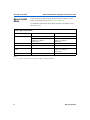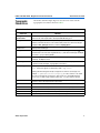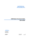
1
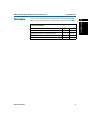
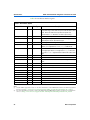
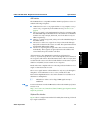
UART with FIFO Buffer MegaCore Function User Guide 101 Innovation Drive San Jose, CA 95134 (408) 544-7000 http://www.altera.com Core Version: Document Version: Document Date: 1.0.2 1.0.2 rev1 June 2002 UART with FIFO Buffer MegaCore Function User Guide Copyright 2002 Altera Corporation. Altera, The Programmable Solutions Company, the stylized Altera logo, specific device designations, and all other words and logos that are identified as trademarks and/or service marks are, unless noted otherwise, the trademarks and service marks of Altera Corporation in the U.S. and other countries. All other product or service names are the property of their respective holders. Altera products are protected under numerous U.S. and foreign patents and pending applications, mask work rights, and copyrights. Altera warrants performance of its semiconductor products to current specifications in accordance with Altera’s standard warranty, but reserves the right to make changes to any products and services at any time without notice. Altera assumes no responsibility or liability arising out of the application or use of any information, product, or service described herein except as expressly agreed to in writing by Altera Corporation. Altera customers are advised to obtain the latest version of device specifications before relying on any published information and before placing orders for products or services. All rights reserved. ii A-UG-MFUART-1.1 Altera Corporation About this User Guide This user guide provides comprehensive information about the Altera® UART with FIFO buffer MegaCore® function. Table 1 shows the user guide revision history. f Go to the following sources for more information: ■ ■ See “Features” on page 9 for a complete list of the core features, including new features in this release Refer to the readme file for late-breaking information that is not available in this user guide Table 1. User Guide Revision History Date June 2002 Description SOPC Builder version 2.6 information added. September 2001 Beta release. May 2002 How to Find Information ■ ■ ■ ■ Altera Corporation First public release. Reference design added. The Adobe Acrobat Find feature allows you to search the contents of a PDF file. Click on the binoculars icon in the top toolbar to open the Find dialog box Bookmarks serve as an additional table of contents Thumbnail icons, which provide miniature previews of each page, provide a link to the pages Numerous links, shown in green text, allow you to jump to related information iii About this User Guide How to Contact Altera UART with FIFO Buffer MegaCore Function User Guide For the most up-to-date information about Altera products, go to the Altera world-wide web site at http://www.altera.com. For additional information about Altera products, consult the sources shown in Table 2. Table 2. How to Contact Altera Information Type Technical support USA & Canada All Other Locations http://www.altera.com/mysupport/ http://www.altera.com/mysupport/ (800) 800-EPLD (3753) (7:00 a.m. to 5:00 p.m. Pacific Time) (408) 544-7000 (1) (7:00 a.m. to 5:00 p.m. Pacific Time) Product literature http://www.altera.com http://www.altera.com Altera literature services [email protected] (1) [email protected] (1) Non-technical customer service (800) 767-3753 (408) 544-7000 (7:30 a.m. to 5:30 p.m. Pacific Time) FTP site ftp.altera.com ftp.altera.com Note: (1) iv You can also contact your local Altera sales office or sales representative. Altera Corporation UART with FIFO Buffer MegaCore Function User Guide Typographic Conventions About this User Guide The UART with FIFO Buffer MegaCore Function User Guide uses the typographic conventions shown in Table 3. Table 3. Conventions Visual Cue Meaning Bold Type with Initial Capital Letters Command names, dialog box titles, checkbox options, and dialog box options are shown in bold, initial capital letters. Example: Save As dialog box. bold type External timing parameters, directory names, project names, disk drive names, filenames, filename extensions, and software utility names are shown in bold type. Examples: fMAX, \qdesigns directory, d: drive, chiptrip.gdf file. Italic Type with Initial Capital Letters Document titles are shown in italic type with initial capital letters. Example: AN 75: High-Speed Board Design. Italic type Internal timing parameters and variables are shown in italic type. Examples: tPIA, n + 1. Variable names are enclosed in angle brackets (< >) and shown in italic type. Example: <file name>, <project name>.pof file. Initial Capital Letters Keyboard keys and menu names are shown with initial capital letters. Examples: Delete key, the Options menu. “Subheading Title” References to sections within a document and titles of on-line help topics are shown in quotation marks. Example: “Typographic Conventions.” Courier type Signal and port names are shown in lowercase Courier type. Examples: data1, tdi, input. Active-low signals are denoted by suffix n, e.g., resetn. Anything that must be typed exactly as it appears is shown in Courier type. For example: c:\qdesigns\tutorial\chiptrip.gdf. Also, sections of an actual file, such as a Report File, references to parts of files (e.g., the AHDL keyword SUBDESIGN), as well as logic function names (e.g., TRI) are shown in Courier. 1., 2., 3., and a., b., c.,... Numbered steps are used in a list of items when the sequence of the items is important, such as the steps listed in a procedure. ■ Bullets are used in a list of items when the sequence of the items is not important. v The checkmark indicates a procedure that consists of one step only. 1 The hand points to information that requires special attention. r The angled arrow indicates you should press the Enter key. f The feet direct you to more information on a particular topic. Altera Corporation v Notes: Contents About this User Guide ............................................................................................................................... iii How to Find Information .............................................................................................................. iii How to Contact Altera .................................................................................................................. iv Typographic Conventions ............................................................................................................. v About this Core ..............................................................................................................................................9 Release Information .........................................................................................................................9 New in Version 1.0.2 ........................................................................................................................9 Features .............................................................................................................................................9 General Description .......................................................................................................................10 Performance ....................................................................................................................................11 Getting Started ............................................................................................................................................13 Software Requirements .................................................................................................................13 Design Flow ....................................................................................................................................13 Download & Install the Function ................................................................................................13 Obtaining the UART with FIFO Buffer MegaCore Function ..........................................13 Installing the UART with FIFO Buffer Files .......................................................................14 UART with FIFO Buffer Directory Structure .....................................................................15 Set Up Licensing .............................................................................................................................16 Append the License to Your license.dat File ......................................................................16 Specify the Core’s License File in the Quartus II Software ..............................................17 UART with FIFO Buffer Walkthrough .......................................................................................17 Create a New Quartus II Project ..........................................................................................18 Launch the MegaWizard Plug-In Manager .......................................................................18 Configuring a Device .....................................................................................................................21 Specifications ..............................................................................................................................................23 Functional Description ..................................................................................................................23 OpenCore Plus Time-Out Behavior ....................................................................................24 Bus Interface ...........................................................................................................................24 Serial Data Interface ...............................................................................................................29 Fixed Modem Interface Signals ............................................................................................30 Configurable Modem Interface Signals ..............................................................................30 Transmitter Operation ...........................................................................................................31 Receiver Operation ................................................................................................................31 Modem Status Lines ..............................................................................................................32 UART Data Formats ..............................................................................................................32 Registers ..........................................................................................................................................34 Receive Status (UART_RSR 00h) .........................................................................................35 Altera Corporation vii Contents Received Data Status (UART_RDS 04h) .............................................................................35 Received Data (UART_RD 08h) ...........................................................................................36 Transmit Status (UART_TSR 0Ch) ......................................................................................36 Transmit Data (UART_TD 10h) ...........................................................................................37 FIFO Control (UART_FCR 14h) ...........................................................................................37 Interrupt Enable Set (UART_IES 18h) .................................................................................38 Interrupt Enable Clear (UART_IEC 1Ch) ...........................................................................38 Interrupt Enable Status (UART_ISR 20h) ...........................................................................39 Interrupt ID (UART_IID 24h) ...............................................................................................39 Mode Configuration (UART_MC 28h) ...............................................................................40 Modem Control (UART_MCR 2Ch) ....................................................................................41 Modem Status (UART_MSR 30h) ........................................................................................42 Divisor Low (UART_DIV_LO 34h) .....................................................................................43 Divisor High (UART_DIV_HI 38h) .....................................................................................43 Device ID (UART_DID 3Ch) ................................................................................................43 Reference Design ............................................................................................................................44 viii Altera Corporation About this Core 1 About this Core Release Information Table 1 provides information about this release of the UART with FIFO Buffer MegaCore function. Table 1. UART with FIFO Buffer Release Information Item Version 1.0.2 Release Date June 2002 Ordering Code IP-UART/FIFO Product ID 0090 Vendor IDs 6AF8 (Standard) 6AF9 (Time-Limited) New in Version 1.0.2 Support for SOPC Builder version 2.6 Features ■ ■ ■ ■ ■ ■ ■ ■ ■ ■ ■ ■ ■ Altera Corporation Description 5 to 8 data bits 1 or 2 stop bits Even, odd, stick, or no parity 75 to 230,400 baud rate Internal 16-byte FIFO buffer for transmit and receive Programmable baud generator divides any input clock by 2 to 65535 and generates the 16 × baud clock Transmit FIFO buffer interrupt for empty indication and transmitter idle indication False-start bit detection Internal diagnostic capabilities – Loop-back control for communications-link fault isolation – Break insertion and detection in loop-back mode Optional modem communication support Two bus interface options: AMBA™ high-performance bus (AHB) or simple peripheral bus (compatible with the Altera Avalon™ bus) Optimized for APEX™ 20KE, APEX 20KC, and Excalibur™ devices Functionally compatible with the UART in the stripe of Excalibur devices 9 About this Core UART with FIFO Buffer MegaCore Function User Guide ■ ■ ■ General Description f Easy-to-use MegaWizard® Plug-In generates parameterized MegaCore functions Includes Verilog HDL models for the ModelSim® simulation tool Supports OpenCore® Plus hardware evaluation The universal asynchronous receiver transmitter module (UART) with first-in first-out (FIFO) buffer MegaCore function performs serial-toparallel conversion on data characters received from a peripheral device or modem, and parallel-to-serial conversion on data characters received via a bus interface. The UART operates in FIFO mode, with the FIFO buffers having a depth of 16 bytes. The status of the UART can be read at any time during operation. The UART reports status information, including the type and condition of the transfer being performed, and any error conditions. The UART offers the choice of two processor bus interface types. The UART with FIFO Buffer MegaCore function is fully software compatible with the UART that is in the embedded stripe in Excalibur devices. For more information on Excalibur devices, refer to the Excalibur Devices Hardware Reference Manual. The OpenCore® feature lets you test-drive Altera MegaCore functions for free using the Quartus® II software. You can verify the functionality of a MegaCore function quickly and easily, as well as evaluate its size and speed before making a purchase decision. However, you cannot generate device programming files. The OpenCore Plus feature set supplements the OpenCore evaluation flow by incorporating free hardware evaluation. The OpenCore Plus hardware evaluation feature allows you to generate time-limited programming files for designs that includes Altera MegaCore functions. You can use the OpenCore Plus hardware evaluation feature to perform board-level design verification before deciding to purchase licenses for the MegaCore functions. You only need to purchase a license when you are completely satisfied with a core’s functionality and performance, and would like to take your design to production. f 10 For more information on OpenCore Plus hardware evaluation using UART with FIFO Buffer, see “OpenCore Plus Time-Out Behavior” on page 24 and AN 176: OpenCore Plus Hardware Evaluation of MegaCore Functions. Altera Corporation UART with FIFO Buffer MegaCore Function User Guide Performance GettingAbout this Core Table 2 shows the performance of the licensed UART with FIFO Buffer MegaCore function with various configurations, which runs at 50 MHz.. About this Core Table 2. Performance Configuration Altera Corporation ESBs LEs AHB interface and no modem interface. 2 677 Peripheral bus interface and modem interface. 2 673 AHB interface and modem interface. 2 690 Peripheral bus interface and no modem interface. 2 660 1 11 About this Core 12 UART with FIFO Buffer MegaCore Function User Guide Altera Corporation Getting Started Software Requirements The UART with FIFO Buffer MegaCore function requires the following software: Design Flow Download & Install the Function 2 A PC running the Windows 98/NT/2000 operating system Quartus II version 2.1 or higher Getting Started ■ ■ This walk-through involves the following steps: 1. Obtain the UART with FIFO buffer MegaCore function. 2. Generate a custom MegaCore function. 3. Implement your system using AHDL, VHDL, or Verilog HDL. 4. License the core and configuring the devices. Before you can start using Altera MegaCore functions, you must obtain the MegaCore files and install them on your PC. The following instructions describe this process. Obtaining the UART with FIFO Buffer MegaCore Function If you have Internet access, you can download MegaCore functions from Altera’s web site at http://www.altera.com. Follow the instructions below to obtain the UART with FIFO Buffer via the Internet. If you do not have Internet access, you can obtain the UART with FIFO Buffer from your local Altera representative. Altera Corporation 1. Point your web browser to http://www.altera.com/ipmegastore. 2. Choose Megafunctions from the Product Type drop-down list box. 3. Type UART in the Keyword Search box. 4. Click Go. 5. Click the link for the Altera UART with FIFO Buffer MegaCore function in the search results table. The product description web page displays. 13 Getting Started UART with FIFO Buffer MegaCore Function User Guide 6. Click the Free Test Drive graphic on the top right of the product description web page. 7. Fill out the registration form, read the license agreement, and click I Agree at the bottom of the page. 8. Follow the instructions on the UART with FIFO Buffer download and installation page to download the function and save it to your hard disk. Installing the UART with FIFO Buffer Files For Windows, perform the following steps: 1. Choose Run (Start menu). 2. Type <path name>\<filename>.exe, where <path name> is the location of the downloaded MegaCore function and <filename> is the filename of the function. 3. Click OK. The UART with FIFO Buffer Installation dialog box appears. Follow the on-line instructions to finish installation. After you have finished installing the MegaCore files, you must specify the directory in which you installed them (e.g., <path>/uart_fifo<version>/lib) as a user library in the Quartus II software. Search for “User Libraries” in Quartus II Help for instructions on how to add these libraries. 14 Altera Corporation UART with FIFO Buffer MegaCore Function User Guide GettingGetting Started UART with FIFO Buffer Directory Structure Figure 1 shows the directory structure for the UART with FIFO Buffer. Figure 1. UART with FIFO Buffer Directory Structure megacore uart_fifo-<version> Contains the UART with FIFO Buffer MegaCore function files and documentation. 2 doc Contains the documentation for the core. Getting Started lib Contains encrypted lower-level design files. After installing the MegaCore function, you should set a user library in the Quartus II software that points to this directory. This library allows you to access all the necessary MegaCore files. lib_time_limited Contains the OpenCore Plus encrypted lower-level design files. After installing the MegaCore function, you should set a user library in the Quartus II software that points to this directory. This library allows you to access all the necessary MegaCore files. ref_design Contains the reference design directories. sim_lib Contains the simulation models provided with the core. modelsim Contains the precompiled libraries for the ModelSim simulation tool. software Contains the assembly and C header files for the core. Altera Corporation 15 Getting Started Set Up Licensing UART with FIFO Buffer MegaCore Function User Guide You can use the Altera OpenCore feature to compile and simulate the UART with FIFO Buffer MegaCore function, allowing you to evaluate it before purchasing a license. You can simulate your UART with FIFO Buffer design in the Quartus II software using the OpenCore feature. However, you must obtain a license from Altera before you can generate programming files or EDIF, VHDL, or Verilog HDL gate-level netlist files for simulation in third-party EDA tools. If you have already purchased a license, you can request a license file for the UART with FIFO Buffer from the Altera web site at http://www.altera.com/licensing and install it on your PC. When you request a license file, Altera e-mails you a license.dat file. If you do not have Internet access, contact your local Altera representative. 1 You must request a license from http://www.altera.com/licensing for OpenCore Plus hardware evaluation. To install your license, you can either append the license to your license.dat file or you can specify the core’s license.dat file in the Quartus II software. 1 Before you set up licensing for the UART with FIFO Buffer, you must already have the Quartus II software installed on your PC with licensing set up. Append the License to Your license.dat File To append the license, perform the following steps: 1. Close the following software if it is running on your PC: ■ ■ ■ ■ ■ 16 Quartus II MAX+PLUS® II LeonardoSpectrum Synplify ModelSim 2. Open the UART with FIFO Buffer license file in a text editor. The file should contain one FEATURE line, spanning 2 lines. 3. Open your Quartus II license.dat file in a text editor. 4. Copy the FEATURE line from the UART with FIFO Buffer license file and paste it into the Quartus II license file. Altera Corporation UART with FIFO Buffer MegaCore Function User Guide 1 5. GettingGetting Started Do not delete any FEATURE lines from the Quartus II license file. Save the Quartus II license file. 1 When using editors such as Microsoft Word or Notepad, ensure that the file does not have extra extensions appended to it after you save (e.g., license.dat.txt or license.dat.doc). Verify the filename in a DOS box or at a command prompt. 2 Specify the Core’s License File in the Quartus II Software 1. Create a text file with the FEATURE line and save it to your hard disk. 1 Altera recommends that you give the file a unique name, e.g., <core name>_license.dat. 2. Run the Quartus II software. 3. Choose License Setup (Tools menu). The Options dialog box opens to the License Setup page. 4. In the License file box, add a semicolon to the end of the existing license path and filename. 5. Type the path and filename of the core license file after the semicolon. 1 6. Do not include any spaces either around the semicolon or in the path/filename. Click OK to save your changes. UART with FIFO Buffer Walkthrough This section describes the design flow using the Altera UART with FIFO Buffer MegaCore function and the Quartus II development system. Altera provides a MegaWizard Plug-In Manager with the UART with FIFO Buffer. The MegaWizard Plug-In Manager, which you can use within the Quartus II software, lets you create or modify design files to meet the needs of your application. You can then instantiate the custom megafunction in your design file. f An Excalibur device walkthrough for the reference design is available in \ref_design\doc\readme.txt. Altera Corporation 17 Getting Started To specify the core’s license file, perform the following steps: Getting Started UART with FIFO Buffer MegaCore Function User Guide Create a New Quartus II Project Before you begin creating a core, you must create a new Quartus II project. With the New Project wizard, you specify the working directory for the project, assign the project name, and designate the name of the top-level design entity. You also specify the UART with FIFO Buffer user library. To create a new project, perform the following steps: 1. Choose Altera > Quartus II-<version> (Windows Start menu) to run the Quartus II software. You can also use the Quartus II Web Edition software if you prefer. 2. Choose New Project Wizard (File menu). 3. Click Next in the introduction (the introduction does not display if you turned it off previously). 4. Specify the working directory for your project. 5. Specify the name of the project. 6. Click Next. 7. Click User Library Pathnames. 8. Type <path>\uart_fifo-<version>\lib\ into the Library name box, where <path> is the directory in which you installed the UART with FIFO Buffer. The default installation directory is c:\megacore. 9. Click Add. 10. Click OK. 11. Click Next. 12. Click Finish. Launch the MegaWizard Plug-In Manager The MegaWizard Plug-In Manager allows you to run a wizard that helps you easily specify options for the UART with FIFO Buffer. To launch the wizard, perform the following steps: 1. 18 Start the MegaWizard Plug-In Manager by choosing the MegaWizard Plug-In Manager command (Tools menu). The MegaWizard Plug-In Manager dialog box is displayed. Altera Corporation UART with FIFO Buffer MegaCore Function User Guide 1 GettingGetting Started Refer to the Quartus II Help for more information on how to use the MegaWizard Plug-In Manager. 2. Specify that you want to create a new custom megafunction and click Next. 3. Select UART FIFO-<version> in the Embedded Systems > Peripherals folder, see Figure 2. 2 Figure 2. Selecting the Core Getting Started 4. Choose the output file type for your design; the wizard supports AHDL, VHDL, and Verilog HDL. 5. Specify a directory, <directory name> and name for the output file, <variation name>. 1 6. Altera Corporation <variation name> and <folder name> must be the same name and the same folder that your Quartus II project uses. Turn on the modem interface and the tristates as required. Select either the peripheral or AHB button (see Figure 7). Click Next. 19 Getting Started UART with FIFO Buffer MegaCore Function User Guide Figure 3. Selecting the Interfaces 7. The final screen lists the design files that the wizard creates (see Figure 4). Click Finish. Figure 4. Design Files When you have created your custom megafunction, you can integrate it into your system design and compile. 20 Altera Corporation UART with FIFO Buffer MegaCore Function User Guide Configuring a Device GettingGetting Started After you have compiled and analyzed your design, you are ready to configure your targeted Altera device. You must license the function before you can generate configuration files. 2 Getting Started Altera Corporation 21 Notes: Specifications Functional Description Figure 1 shows the UART with FIFO buffer MegaCore function block diagram. Figure 1. Block Diagram clk txd reset_n rxd irq cts haddr[5:0] dsr hwrite rts htrans[1:0] dtr hsize[1:0] hreadyi Modem Control Interface AHB Interface 3 ri_i_n ri_o_n hready0 Specifications hsel ri_i_n dcd_ri_oe UART hresp[1:0] dcd_o_n dcd_n dcd_i_n hrdata[7:0] hwdata[7:0] Tristate - no Tristate - yes sel addr[3:0] write_n read_n Peripheral Bus Interface writedata[7:0] readdata[7:0] Either the AHB Interface or the peripheral bus interface depending on which you select in the MegaWizard Plug-In Altera Corporation Only if you select modem in the MegaWizard Plug-In 23 Specifications UART with FIFO Buffer MegaCore Function User Guide OpenCore Plus Time-Out Behavior The following events occur when the OpenCore Plus hardware evaluation times out: ■ ■ ■ ■ ■ ■ The timed_out signal goes from low to high The TO bit in the UART device ID register is set The core behaves as though the serial interface is disconnected—it deasserts txd (goes high); and ignores rxd. The signal that drives rxd is driven high The rest of the core operates as usual—the bus interface and internal registers are fully functional Characters can still be written to the transmit buffer and appear to be transmitted at the appropriate time, but are not because txd is high Remaining characters in the receive buffer can be read out You can also read the UART device ID register to determine the core’s OpenCore Plus status. A time-limited UART with FIFO Buffer MegaCore function runs for approximately 18 hours for a 33 MHz (approximately 2.2 × 10¹² clock cycles). f For more information on OpenCore Plus hardware evaluation, see “General Description” on page 10 and AN 176: OpenCore Plus Hardware Evaluation of MegaCore Functions. Bus Interface The core has a bus slave interface that you select to operate in one of the following modes in the MegaWizard Plug-In: ■ ■ AHB Peripheral The advanced microcontroller bus architecture (AMBA) highperformance bus (AHB) slave interface provides an industry standard onchip bus interface that can be used for either Excalibur devices or any system where an AHB has been adopted as an on-chip bus standard. The simple peripheral interface provides a low-level interface to the core that can be used for either easy bridging to other bus standards or connecting directly to an Avalon™ bus system. 1 24 In either mode user-defined logic that connects to the bus interface must be synchronous to the positive edge of clk. Altera Corporation UART with FIFO Buffer MegaCore Function User Guide GettingSpecifications The AHB slave interface offers higher performance, because primarily it operates with one wait state (compared to zero wait states for the peripheral slave interface), which allows you to register the hrdata output. 1 You can add external logic to the low-level peripheral slave interface to provide one-wait state behavior. The cores \lib directory contains a class.ptf file that shows the peripheral technology file (PTF) settings for the bus interface as an AHB slave interface and a low-level peripheral slave interface. In an AMBA system a simple peripheral such as a UART has an AMBA peripheral bus (APB) interface. If you want to standardize on an APB interface, you can make the peripheral slave interface behave like an APB interface using minimal external logic. 3 Specifications Altera Corporation 25 Specifications UART with FIFO Buffer MegaCore Function User Guide Table 1 shows the bus interface signals. Table 1. Bus Interface Signals Signal Name Type Bus Type Description – System clock input. All signals on the core are synchronous to the positive edge of this clock except for all the modem control inputs, which are treated as asynchronous inputs and synchronized to clk within the core before processing. clk Input reset_n Input – Active-low reset input. irq Output – Active-high interrupt output. The function of this signal is not affected by the chosen bus interface type. sel Input Peripheral Select signal—must be high for a transaction to occur. addr[3:0] Input Peripheral Address bus input. The value on this bus represents a word address, so is equivalent to haddr[5:2], in AHB mode. write_n Input Peripheral Active-low write enable. A write to a register takes place on the clock edge upon which sel is high and write_n is low. The addr and writedata signals must be valid on this same clock edge. read_n Input Peripheral Active-low read enable. writedata[7:0] Input Peripheral Write data. readdata[7:0] Output Peripheral Read data is valid when addr is valid, sel is high and read_n is low. hsel Input AHB Note (1) haddr[5:0] Input AHB Byte address. Note (1) hwrite Input AHB Note (1) htrans[1:0] Input AHB Note (1) hsize[1:0] Input AHB Note (1) hreadyi Input AHB The HREADY input to a slave. Note (1), Note (2) hreadyo Output AHB The HREADY output from a slave. Note (1), Note (2) hresp[1:0] Output AHB Note (1) hrdata[7:0] Output AHB Note (1) hwdata[7:0] Input AHB Note (1) Note: (1) (2) 26 See the AMBA Specification revision 2.0. For more information on the AHB interface refer to the AMBA Specification Revision 2.0 at http://www.arm.com/armtech.nsf/html/AMBA_Spec?OpenDocument&style=IP_Solutions For more information on HREADY, refer to the ARM web site AMBA FAQ "Is HREADY an input or an output from slaves ?" at http://www.arm.com/support.nsf/html/amba!OpenDocument&ExpandSection=2#_Section2 Altera Corporation UART with FIFO Buffer MegaCore Function User Guide GettingSpecifications AHB Interface The AHB interface is compatible with the AMBA Specification revision 2.0 with the following exceptions: ■ ■ ■ ■ ■ AHB slaves have an hready input and an hready output (hreadyi and hreadyo respectively for Excalibur devices), see Note (2) on page 26 The hsize signal is only implemented as 2 bits for consistency with the embedded stripe in Excalibur devices. It is therefore assumed that transfers are only ever byte, half-word, word or double-word, (8 to 64bits respectively) The hprot signals are ignored, as they are for the embedded stripe in Excalibur devices The hwdata and hrdata signals are always 8-bits wide although byte, half-word and word accesses are valid. The system interconnect must handle different bus widths The hburst input signals are ignored as the core treats each beat individually. These signals can ignored, because the address and control must always be valid for each beat Reads and writes complete with one wait state per beat whether or not a single or a burst transaction occurs. The hrdata signal returns valid read data for only one cycle during the data phase. At all other times hrdata is zero, which allows bus interconnect implementations to use an OR structure for read data as an alternative to multiplexers. 1 f The behavior of the core for illegal AHB signal activity is undefined. For more information on the AHB interface refer to the AMBA Specification Revision 2.0 at http://www.arm.com/armtech.nsf/html/AMBA_Spec?OpenDocument &style=IP_Solutions Peripheral Bus Interface Figure 2 shows a single write transfer followed by bus inactivity, followed by a single read transfer. Altera Corporation 27 3 Specifications All transactions to the AHB interface must be word-aligned (i.e., haddr[1:0]must always be zero). Non word-aligned accesses return an error response and will not affect the internal state of the core. Byte, halfword and word accesses are allowed and all behave in the same way but double-word (64-bit) accesses return an error response. Specifications UART with FIFO Buffer MegaCore Function User Guide Figure 2. Simple Peripheral Interface—Write and Read Operation Note (1) [1] [2] [3] [5] [4] clk sel write_n read_n addr writedata readdata Note: (1) The numbers in brackets refer to the steps in the following text. Write Transfer A write transfer occurs on each positive clock edge when sel is high, write_n is low, and read_n is high. The core samples the write address and (addr) and the data write (writedata) on the same clock edge as the control signals. Figure 2 shows the following typical sequence of events: 1. All inputs are generated synchronously on the positive edge of clk. 2. All inputs are sampled by the core on the positive edge of clk and writedata is sampled directly into the core registers. 1 Any internal actions arising from a write also occur on this clock edge. Read Transfer A read transfer occurs on each positive clock edge when sel is high, read_n is low, and write_n is high. The readdata signal is valid a combinatorial delay after addr is valid and is invalid as soon as addr is invalid. Figure 2 shows the following typical sequence of events: 28 Altera Corporation GettingSpecifications UART with FIFO Buffer MegaCore Function User Guide 3. All inputs are generated on the positive edge of clk. 4. The readdata signal is valid a combinatorial delay after addr is valid. 5. The core samples all inputs on the positive edge of clk. Any internal actions arising from a read also occur on this clock edge. 1 Your logic must also sample readdata on this same clock edge. With the peripheral bus, if you provide the correct address, the corresponding register contents are available on the readdata output combinatorially (sel or read_n need not be active). The correct address is sufficient for external logic to access the contents of each readable register, and gives you additional flexibility. However, you cannot assume that a read transfer has taken place unless read_n and sel are also sampled active on the appropriate clock edge. This sampling ensures that read transfers that have side-effects operate correctly. To interface to an Avalon system, you should define the transfer type with the following settings: ■ ■ ■ Fundamental transfer Zero wait states Zero setup and hold The core’s \lib and \lib_time_limited directories contain a class.ptf file that shows the settings for use in an Avalon system. Serial Data Interface Table 2 shows the serial data interface signals. Table 2. Serial Data Interface Signals Signal Name Type Description txd Output Serial data output to the communications link. On reset txd is set high rxd Input Serial data input from the communications link. Altera Corporation 29 Specifications Interfacing to an Avalon System 3 Specifications UART with FIFO Buffer MegaCore Function User Guide Fixed Modem Interface Signals The following modem signals are available if you turn on modem interface in the MegaWizard Plug-In (see “Launch the MegaWizard PlugIn Manager” on page 18). Table 3 shows the fixed modem interface signals. Table 3. Fixed Modem Interface Signals Name Type Description dtr_n Output Data terminal ready, active-low signal. When dtr_n is active, the core is ready to establish a communications link rts_n Output Request-to-send, active-low signal. When rts_n is active the core informs the peer device that the core is ready to receive data dsr_n Input Data set ready, active-low signal. When dsr_n is active, the peer device is ready to establish the communications link with the core. cts_n Input Clear-to-send, active-low signal. When cts_n is active, the peer device can accept characters Configurable Modem Interface Signals The configurable modem interface signals (see Table 4) are applicable if you turn on the tristates in the MegaWizard Plug-In (see “Launch the MegaWizard Plug-In Manager” on page 18). 1 The OE bit in the mode configuration register controls the direction of these signals. Table 4. Configurable Modem Interface Signals (tristates selected) Name Type Description ri_n Tristate Active-low ring Indicator signal. When active this indicates that a telephone ringing signal is being received by the modem. dcd_n Tristate Data carrier detect, active-low signal. When active indicates that the data carrier is being detected by the modem. 30 Altera Corporation GettingSpecifications UART with FIFO Buffer MegaCore Function User Guide Table 5 shows the signals that are applicable if you do not select the tristates option in the MegaWizard Plug-In. Table 5. Configurable Modem Interface Signals (tristates not selected) Name Type Description ri_i_n Input Output of the tristate driver for ri_n feeding back into the modem control interface. ri_o_n Output Input to the tristate driver for ri_n. dcd_i_n Input Output of the tristate driver for dcd_n feeding back into the modem control interface. dcd_o_n Output Input to the tristate driver for dcd_n. dcd_ri_oe Output Active-high output enable for both tristate drivers. Transmitter Operation Data written to the transmit data register, UART_TD, is queued in the transmit FIFO buffer ready for transmission. The transmit FIFO level, TX_LEVEL, in the transmit status register, UART_TSR, indicates the number of bytes currently stored in the transmit FIFO buffer. 3 Setting the transmit idle interrupt enable bit, TIE, in the interrupt-enable set register, UART_IES, causes an interrupt when the transmitter becomes idle after sending the last byte in the transmit FIFO buffer. The transmitter becomes idle when there is no data in the transmit FIFO buffer and the transmit shift register becomes empty. The transmit idle (TII) and transmit interrupt (TI) are both cleared by reading UART_TSR. Receiver Operation Received data is stored in the receive FIFO buffer and is removed by reading the received data register, UART_RD. If the receive interrupt bit, RE, of the interrupt-enable set register, UART_IES, is set, an interrupt is generated when the number of bytes in the FIFO buffer reaches the number equal to the receive threshold level, RX_THR, in the FIFO buffer control register, UART_FCR. This interrupt is cleared by reading the receive status register, UART_RSR, which indicates the number of bytes currently in the FIFO buffer. Altera Corporation 31 Specifications Data written to UART_TD when the FIFO buffer is full is lost. If the transmit interrupt-enable bit, TE, is set in the interrupt-enable set register, UART_IES, a transmitter interrupt is generated when the number of bytes in the transmit FIFO buffer falls to the level equal to the transmit threshold level field, TX_THR, of the FIFO control register, UART_FCR. Specifications UART with FIFO Buffer MegaCore Function User Guide A receive interrupt is also generated when RE is set, the receive FIFO buffer is not empty, and no further data has been received after 32 UART bit-times. Any errors occurring during the reception of the next byte are indicated in UART_RDS, and must be read before the next byte is read. Modem Status Lines The value of the modem status lines that are inputs can be tested by reading the UART_MSR register. The values of the modem status outputs are controlled by bits within UART_MCR. UART Data Formats Figure 3 shows the data format when an 8-bit word with parity has been selected. A data bit value of 1 corresponds to the serial line being low (mark). Figure 3. UART Data Format bittime TXD start d0 d1 d2 d3 d4 d5 d6 d7 parity stop start d1 d2 d3 d4 d5 d6 d7 parity stop start bittime RXD start d0 BAUDRATE = BITTIME = CLK/(divisor × 16) bits/s 1/BAUDRATE Table 6 gives a brief description of the data signal components. 32 Altera Corporation UART with FIFO Buffer MegaCore Function User Guide GettingSpecifications Table 6. Data Signal Components START_BIT TXD and RXD are normally high. When a character is being transmitted, TXD is driven low for the duration of 1-bit time. The receiver always samples the RXD line. When it detects a start bit, it starts shifting a new character in A character can be programmed for 5 to 8 bits. Both transmitting and receiving UARTs must be programmed for the same settings, otherwise communication fails PARITY Parity generation and checking can be enabled or disabled. If parity is disabled, no parity bit is transmitted, and the receiver does not expect to receive a parity bit. If parity is enabled, it can be even, odd, or stick parity: Even parity—Parity bit is 1, if the character has an odd number of 1s Odd parity—Parity bit is 1, if the character has an even number of 1s Stick parity—Parity bit can be forced to 1 or 0 STOP BIT Stop bits are the last bits to be transmitted or received for each character. A stop bit is a 1. The number of stop bits can be programmed to be 1- or 2-bit times. Stop bits act like a spacer between characters if they are transmitted back-to-back. Both receiving and transmitting UARTs must be programmed for the same settings. The UART only checks the first stop bit BREAK A break is detected if RXD is held low longer than a character-time. (A character-time is the time to transmit or receive a character including start, parity and stop bits.) This usually happens if RXD is disconnected, or the transmitting UART forced a break or is turned off. A break can be forced by setting the break bit in the modem control register, UART_MCR Altera Corporation 33 3 Specifications DATA Specifications UART with FIFO Buffer MegaCore Function User Guide Registers At reset, all registers hold the value 0 unless otherwise specified. Table 7 shows the effect of a read or a write within the UART MegaCore function. Table 7. Register Access Abbreviation R Description Read access (no side effects). RO Read only. R* Read access with possible side effects (such as clearing some of the bits or clearing an interrupt). W Writes of 1 or 0 set writable bits to the values specified. S Writes of 1 set bits. Writes of 0 do nothing. C Writes of 1 clear the appropriate bits. Writes of 0 do nothing. Table 8 shows the UART control registers. Table 8. UART Registers Byte Offset (H) haddr[5:0] Value Word Offset addr[3:0] Value Mnemonic Name Access 00 0000B UART_RSR Receive status register 04 0001B UART_RDS Received data status R* R 08 0010B UART_RD Received data R* 0C 0011B UART_TSR Transmit status register R* 10 0100B UART_TD Transmit data W 14 0101B UART_FCR FIFO control register R/W 18 0110B UART_IES Interrupt-enable set register R/S 1C 0111B UART_IEC Interrupt-enable clear register R/C 20 1000B UART_ISR Interrupt status register R 24 1001B UART_IID Interrupt ID register R 28 1010B UART_MC Mode-configuration register R/W 2C 1011B UART_MCR Modem control register R/W 30 1100B UART_MSR Modem status register R* 34 1101B UART_DIV_LO Divisor register (high) R/W 38 1110B UART_DIV_HI Divisor register (low) R/W 3C 1111B UART_DID Device ID R At reset, all registers hold the value 0 unless otherwise specified. 34 Altera Corporation GettingSpecifications UART with FIFO Buffer MegaCore Function User Guide 1 The register definitions and operation for this MegaCore function are identical to those for the UART that is in the embedded stripe of Excalibur devices, except the device ID register. Receive Status (UART_RSR 00h) Table 9 shows the receive status register format. Table 9. Receive Status Register Format Data Bit Mnemonic Access Description 4:0 RX_LEVEL R* 6:5 0 R* The number of bytes in the receive FIFO buffer. Reserved for future use. 7 RE R* Receive error. This bit is set when there is at least one parity error, framing error, break indication, or overrun error at any location in the receive FIFO buffer. 3 Reading this register clears the receive-interrupt bit, RI, in UART_ISR. Specifications Received Data Status (UART_RDS 04h) Table 10 shows the received data status register format. Table 10. Received Data Status Register Format Data Bit Mnemonic Access Description 0 OE R Overrun error. Set when a receive-overrun occurs. This happens if the receive FIFO buffer is full and a character is received into the shift register, destroying the data currently in it. This status is associated with the character after the one that was lost due to overrun. 1 PE R Parity error. Set if the received parity differs from the expected value. 2 FE R Framing error. Set if a valid stop bit is not detected. This status bit is associated with the next character to be read from UART_RD. 3 BI R Break indicator. Set if a break is received. This occurs when RXD is low for more than one character transmission time (from start bit to stop bit): a single 0 is received. This status is valid with the 0 character; one break-indicator flag and 0 is loaded into the receive FIFO buffer. The next character is only written into the receive FIFO buffer when the next valid start bit is detected. 7:4 0 R Reserved for future use. Altera Corporation 35 Specifications UART with FIFO Buffer MegaCore Function User Guide The above errors are associated with the particular character in the FIFO buffer that they apply to. The error is revealed when its associated character is at the top of the FIFO buffer. Received Data (UART_RD 08h) Table 11 shows the received data register format. Table 11. Received Data Register Format Data Bit Mnemonic 7:0 RX_DATA Access R Description Receive data. When you write 1 to the RC bit in UART_FCR, the core clears the receive FIFO buffer (i.e. the internal FIFO buffer pointers are reset). However, the contents of the receive FIFO buffer memory are not necessarily set to zero. If a read from the receive FIFO buffer happens directly after reset, and no data has been written to the receive FIFO buffer, the data read is undefined. When the FIFO buffer is full, no more data can be written into the FIFO buffer. Transmit Status (UART_TSR 0Ch) Table 12 shows the transmit status register format. Table 12. Transmit Status Register Format Data Bit Mnemonic Access Description 4:0 TX_LEVEL R* Transmit FIFO buffer level (the number of characters in the transmit FIFO buffer). 6:5 0 R* Reserved for future use. 7 TXI R* Transmitter idle. Set when the transmitter shift register becomes empty and there are no more characters in the transmit FIFO buffer. Cleared when UART_TSR is read. Reading this register clears TI and TII in UART_ISR. 36 Altera Corporation GettingSpecifications UART with FIFO Buffer MegaCore Function User Guide Transmit Data (UART_TD 10h) Table 13 shows the transmit data register format. Table 13. Transmit Data Register Format Data Bit Mnemonic 7:0 TX_DATA Access W Description Transmit data. Each write to this register stores the character in the transmit FIFO buffer. FIFO Control (UART_FCR 14h) Table 14 shows the FIFO control register format. Table 14. FIFO Control Register Format Data Bit Mnemonic Access Description TC R/C Clear transmit FIFO buffer. TC is always read as 0 and is self-clearing. 1 RC R/C Clear receive FIFO buffer. RC is always read as 0 and is self-clearing. 4:2 TX_THR R/W Transmit threshold level. The threshold level encoding is as follows: 000—0 001—2 010—4 011—8 100—10 7:5 RX_THR R/W Receive threshold level. The threshold level encoding is as follows: 000—1 001—2 010—4 011—6 100—8 3 Specifications 0 When the receive FIFO buffer depth is equal to, or greater than, the number of characters programmed in RX_THR, the receive-interrupt bit, RI, in UART_ISR is set. When the transmit FIFO buffer depth is equal to, or less than, the number of characters programmed in TX_THR, the transmit-interrupt bit, TI, in UART_ISR is set. Writing 1 to the clear-receive bit, RC, clears the receive FIFO buffer counters. The shift register is not cleared. Altera Corporation 37 Specifications UART with FIFO Buffer MegaCore Function User Guide Writing 1 to the clear-transmit bit, TC, clears the transmit FIFO buffer counters and sets the TII interrupt. The shift register is not cleared. Interrupt Enable Set (UART_IES 18h) Table 15 shows the interrupt enable set register format. Table 15. Interrupt Enable Set Register Format Data Bit Mnemonic Access Description 0 RE R/S Enable receive-interrupt. 1 TE R/S Enable transmit-interrupt. 2 TIE R/S Enable transmit-idle-interrupt. 3 ME R/S Enable modem-status-interrupt. 7:4 0 R Reserved for future use. Reading UART_IES indicates which bits of the interrupt mask are set. Interrupt Enable Clear (UART_IEC 1Ch) Table 16 shows the interrupt enable clear register format. Table 16. Interrupt Enable Clear Register Format Data Bit Mnemonic Access Description 0 RE R/C Clear receive-interrupt enable. 1 TE R/C Clear transmit-interrupt enable. 2 TIE R/C Clear transmit-idle-interrupt enable. 3 ME R/C Clear modem-status-interrupt enable. 7:4 0 R Reserved for future use. Reading UART_IEC indicates which bits of the interrupt mask are set. 38 Altera Corporation GettingSpecifications UART with FIFO Buffer MegaCore Function User Guide Interrupt Enable Status (UART_ISR 20h) Table 17 shows the interrupt status register format. Table 17. Interrupt Status Register Format Data Bit Mnemonic Access Description 0 RI R Receive interrupt. Set either when there has been a received-character timeout or the received-data flag goes from low to high. Cleared by reading UART_RSR. 1 TI R Transmit interrupt. Set when the number of characters in the transmit FIFO buffer goes from being more than the transmit threshold to being equal to or less than the transmit threshold. (The transmit threshold is TX_THR in UART_FCR). Cleared by reading UART_TSR. 2 TII R Transmitter Idle interrupt. Set when there is no data in the transmit FIFO buffer and the transmit shift register becomes empty. Cleared by reading UART_TSR. 3 MI R Modem-status interrupt. Set when any of DDCD, TERI, DDSR or DCTS bits within UART_MSR are set. Cleared by reading UART_MSR. 7:4 0 R Reserved for future use. Write as 0 to ensure future compatibility. 3 Specifications 1 The received data flag goes high when the level of the receive FIFO buffer is equal to or greater than the received threshold level. 1 The received-character timeout is an internal timeout signal, which is asserted when the receive FIFO buffer is not empty and no further data has been received over a 32-bit period. Interrupt ID (UART_IID 24h) Table 18 shows the interrupt ID register format. Table 18. Interrupt ID Register Format Data Bit Mnemonic Access Description 2:0 IID R Interrupt ID: 000 = no interrupts pending 001 = RI is the highest priority pending interrupt. 010 = TI is the highest priority pending interrupt. 011 = TII is the highest priority pending interrupt. 100 = MI is the highest priority pending interrupt. 7:3 0 R Reserved for future use. Altera Corporation 39 Specifications UART with FIFO Buffer MegaCore Function User Guide Mode Configuration (UART_MC 28h) Table 19 shows the mode configuration register format.. Table 19. Mode Configuration Register Format Data Bit Mnemonic Access Description 1:0 CLS R/W Character length. Selects the number of bits used to specify characterlength: 00—5 bits 01—6 bits 10—7 bits 11—8 bits 2 ST R/W Stop bits. Selects the number of stop bits transmitted: 0—1 stop bit 1—2 stop bits. 3 PE R/W Parity enable. Selects whether parity is added (on transmit) and checked (on receive). 4 EP R/W Even parity. Selects between even parity and odd parity. When even parity is selected, the number of 1s (that is, data plus parity) is even. When odd parity is selected, the number of 1s (that is, data plus parity) is odd. 5 SP R/W Stick parity. Forces the parity bit to either 1 or 0. 6 OE R/W Controls the behavior of DCD and RI pins. When it is 1, DCD and RI are outputs controlled from the UART_MCR. When it is 0, they are inputs whose status is reflected in UART_MSR. 7 0 R Reserved for future use. 40 1 CLS selects the length of transmitted and received characters. For character lengths less than 8 bits, the least significant bits in UART_TD and UART_RD define the character, and the most significant bits are ignored on transmit and set to zero on receive. 1 ST selects the number of stop bits transmitted. The receiver checks only the first stop bit, regardless of the number of stop bits transmitted. Altera Corporation GettingSpecifications UART with FIFO Buffer MegaCore Function User Guide Table 20 summarizes how the interactions between PE, EP and SP affect parity mode configuration.. Table 20. Mode Configuration Bits SP EP PE Description X X 0 No parity. 0 0 1 Odd parity. 0 1 1 Even parity. 1 0 1 ’1’ parity. 1 1 1 ’0’ parity. Modem Control (UART_MCR 2Ch) Table 21 shows the modem control register format. Table 21. Modem Control Register Format Access 3 Description 0 RTS R/W Request to send. Controls the state of the RTS pin. When it is 1, RTS_n is set active (i.e., low). Can be forced into an inactive state if AR is set. 1 DTR R/W Data terminal ready. Controls the state of the DTR pin. When it is 1, DTR_n is set active (i.e., low). 2 RI R/W Ring indicator output. Controls the state of the RI pin, when it is an output. When RI is 1, RI_n is set active (i.e., low). 3 DCD R/W Data carrier detect output. Controls the state of the DCD pin when it is an output. When DCD is 1, DCD_n is set active (i.e., low). 4 LB R/W When set, puts the UART into loop-back mode at the serial interface. 5 BR R/W Transmit break. Forces TXD to 0 immediately if no serial data is being transmitted. If data is currently being transmitted, TXD is forced to 0 after the current contents of the transmit shift register have been transmitted. The transmitter is not stopped when this bit is set. 6 AR R/W Auto rts_n. When set, the rts_n pin is de-asserted when there are 16 bytes in the receive FIFO buffer (indicating to the transmitter that new data cannot be accepted). When there are fewer than 16 bytes in the receive FIFO buffer, the state of AR is ignored and the state of the rts_n pin depends only on the value of RTS. 7 AC R/W Auto CTS. When set, the transmitter does not start transmitting a character unless CTS in UART_MSR is asserted. It continues to transmit the current character if CTS changes state during the character transmission. Altera Corporation 41 Specifications Data Bit Mnemonic Specifications UART with FIFO Buffer MegaCore Function User Guide 1 Ensure that the transmit FIFO buffer is empty before setting BR, because data in the transmit FIFO buffer might be lost or corrupted when it is set. Data in the transmit shift register is not affected. In loop-back mode, the output pins are set high (inactive) and the input pins are ignored. Table 22 shows how the output signals from the UART are connected to the inputs. Table 22. Input-Output Connections Output Connected to Input TXD RXD RTS_n CTS_n DTR_n DSR_n RI_n output RI_n input DCD_n output DCD_n input Modem Status (UART_MSR 30h) Table 23 shows the modem status register format. Table 23. Modem Status Register Format Data Bit Mnemonic Access Description 0 DCTS R* Set when the CTS_n pin changes state. 1 DDSR R* Set when the DSR_n pin changes state. 2 TERI R* Set when the RI_n pin changes from low to high. 3 DDCD R* Set when the DCD_n pin changes state. 4 CTS R* Set when the CTS_n pin is at a low value. 5 DSR R* Set when the DSR_n pin is at a low value. 6 RI R* Set when the RI_n pin is at a low value. 7 DCD R* Set when the DCD_n pin is at a low value. When the DCD_n and RI_n pins are selected as outputs, the appropriate bits in this register are always 0. When any of the bits DDCD, TERI, DDSR and DCTS are set, the modemstatus interrupt bit, MI, is set in UART_ISR. Reading this register clears DDCD, TERI, DDSR and DCTS to zero (and clears MI). 42 Altera Corporation GettingSpecifications UART with FIFO Buffer MegaCore Function User Guide Divisor Low (UART_DIV_LO 34h) Table 24 shows the divisor register (low) format. Table 24. Receive Status Register Format Data Bit 7:0 Mnemonic DIV Access R/W Description The least significant byte of the 16-bit divisor value. Divisor High (UART_DIV_HI 38h) Table 25 shows the divisor register (high) format. Table 25. Receive Status Register Format Data Bit 7:0 Mnemonic DIV Access R/W Description The most significant byte of the 16-bit divisor value. If a divisor value of 0 or 1 is programmed, the baud rate divisor divides by 2. For example, to generate a baud rate of 230,400 from a clk of 33 MHz, the ideal divisor is: 33,000,000/(16 × 230,400) = 8.95 A programmed value of 9 gives a 0.5% error from the ideal baud rate, which is comfortably within the bounds allowed by the RS232 specification. Device ID (UART_DID 3Ch) The device ID register (UART_DID) at address 0x3C is read as 0x00 for a licensed MegaCore function. Table 26 shows the device ID register format. Altera Corporation 43 3 Specifications To load a value, UART_DIV_LO must be loaded before UART_DIV_HI. The values in these registers combine to form the divisor latch value, which is used in the clock divider to generate the UART baud clock. The baud rate generated by the UART is the clk frequency, divided by (UART_DIV × 16). Specifications UART with FIFO Buffer MegaCore Function User Guide 1 The UART_DID register is not documented in the ARM-based Embedded Processor PLDs Hardware Reference Manual, but a read access to the equivalent offset address (registers base + 2BCh) is fully compatible with the UART_DID register operation (i.e., it always reads as 00h). Table 26. Device ID Register Format Data Bit 0 Mnemonic Access RO OC Description OpenCore Plus status. 1= time limited core 0 = a non-time limited core and TO is always 0. 1 TO RO 0 = the core is fully functional. 1 = an OpenCore Plus time-out has occurred. 7:2 0 RO Reserved for future use. Reference Design f 44 Altera supplies a reference design for Excalibur devices with the UART with FIFO Buffer MegaCore function. For more information on the reference design, see the document ref_design_readme.txt in the \ref_design\docs directory. Altera Corporation