1
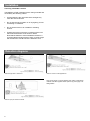
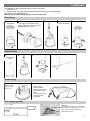
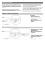
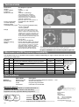
Wiring examples Channel 1 (switched output) of the MWS3A-AT-AD can either be used to switch a separate channel of standard, non-dimming luminaires, or to isolate the mains supply to dimming ballasts (saving on the standby current of the ballasts). Multiple luminaires may be connected in parallel to Channel 1 (via the N and L/Out terminals) as long as the maximum total load is not exceeded. Channel 2 (dimmable output) of the MWS3A-AT-AD can be used to control the light output of luminaires that are fitted with dimming ballasts/transformers. Up to 10 ballasts/transformers can be connected in parallel to Channel 2 (via the DIM– and DIM+ terminals). Ensure that correct polarity is maintained at each ballast. The wiring examples below show common methods of connecting the output channels for a single detector unit. Example 1: Single channel switching Functionality Simple On/Off load control. Presence detection. Absence detection using an ATBB-IN Input Unit and associated switch/button plate. Manual On/Off control using IR Handset. Lux switching. Example 2: Single channel dimming 1-10V 4 Functionality Dimmable load control via suitable ballast/transformer. Mains power to ballast switched by channel 1. Presence or absence detection (with or without Lux Level control). Manual scene/level control using IR Handset or AT-BB-IN Input Unit and associated switch/button plate. Optional Maintained Illuminance Level control.