1
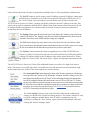
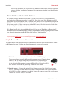
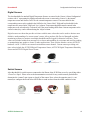
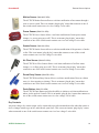
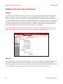
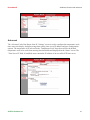
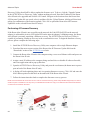
Installation
Room Alert 4E
screen of the Room Alert 4E unit and enter the IP address settings on the ‘Network’ tab. After
doing so, click the ‘Save Settings’ button, wait 10 seconds and re-attach the Room Alert 4E unit to
the network.
Device Not Found Or Invalid IP Address
If the Room Alert 4E is not discovered by the AVTECH Device Discovery Utility, the network
may be blocking UDP broadcast packets on port 30718. Even if the Room Alert 4E obtains a valid IP
address, this can prevent the Room Alert 4E unit from being discovered. To resolve this issue, check the
DHCP server for the MAC address listed on the label located on the bottom of the Room Alert 4E unit.
If this is not possible or if there is not an entry in the DHCP server, follow the instructions listed under
the ‘Static-Only Networks’ subsection above.
If the Room Alert 4E unit is discovered although has a ‘169.xxx.xxx.xxx’ IP address, the Room Alert 4E
unit may not have been connected properly or DHCP assignment may currently be getting blocked. In either
case, follow the instructions listed in the ‘Static-Only Networks’ subsection above.
NOTE: If the instructions provided do not allow configuration of the Room Alert 4E unit, please initiate a Live Chat technical
support request on AVTECH.com or send an email support request to [email protected].
Step 4: Connect Sensors And Accessories
The graphics below identify the connection ports and channels of the Room Alert 4E ID box that are visible
on the front and rear panels. Use these to connect the appropriate sensors and accessories.
Front View (Room Alert 4E ID Box)
A/B
C
A. Digital Temperature Sensors — Connect the included AVTECH Digital
Temperature Sensor to one of the External Environment Sensor Channels shown
above (A / B). The Digital Temperature Sensor provides a real-time digital
temperature reading at the location of the temperature probe. Position the sensor
in the desired location, running the sensor cable back to the Room Alert 4E ID
box. DO NOT remove the red plastic cap from the tip of the sensor.
B. Switch Sensors — Connect the optional Switch Sensors to one of the Switch Sensor Contact
Set (C). Position the sensor in the desired location, running the sensor cable back to the Room
Alert 4E ID box. This is an instant ‘plug & play’ sensor that connects to one of the switch sensor
contact sets via a low voltage 2-wire cable.
8
AVTECH Software Inc.