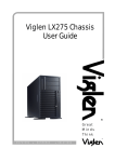
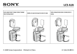
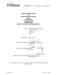
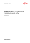
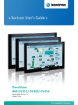
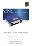
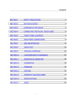
1
Chassis User Guide ® Great Minds Think C O M P U T E R S . N E T W O R K S . ® S O L U T I O N S Viglen, EMC and the ‘CE’ mark CE Marking As we begin the 21st century, European standards are being harmonised across borders. If products comply with the same standards in all European countries, product exporting and importing is made simple - paving our way to a common market. If you buy a product with a 'CE' mark on it (shown below), on the box, in the manual, or on the guarantee - it complies with the currently enforced directive(s). Introduction to EMC EMC (Electromagnetic Compatibility) is the term used to describe certain issues with RF (Radio Frequency) energy. Electrical items should be designed so they do not interfere with each other through RF emissions. E.g. If you turn on your microwave, your television shouldn't display interference if both items are CE marked to the EMC directive. If emitted RF energy is not kept low, it can interfere with other electrical circuitry - E.g. Cars Automatic Braking Systems have been known to activate by themselves while in a strong RF field. As this has obvious repercussions ALL electrical products likely to cause RF related problems have to be 'CE' marked from 1st January 1996 onwards. If a product conforms to the EMC directive, not only should its RF emissions be very low, but its immunity to RF energy (and other types) should be high. The apparatus has to resist many 'real world' phenomena such as static shocks and mains voltage transients. Viglen’s Environment laboratory To gain a 'CE' mark, the Viglen computer range has had to undergo many difficult tests to ensure it is Electromagnetically Compatible. These are carried out in the in-house 'Environment lab' at Viglen Headquarters. We have made every effort to guarantee that each computer leaving our factory complies fully with the correct standards. To ensure the computer system maintains compliance throughout its functional life, it is essential you follow these guidelines. Install the system according to Viglen’s instructions If you open up your Viglen System: Keep internal cabling in place as supplied. Ensure the lid is tightly secured afterwards Do not remove drive bay shields unless installing a 'CE' marked peripheral in its place The clips or ‘bumps' around the lips of the case increase conductivity - do not remove or damage. Do not remove any ferrite rings from the L.E.D cables. Only use your Viglen computer with 'CE' marked peripherals This system has been tested in accordance with European standards for use in residential and light industrial areas-this specifies a 10 meter testing radius for emissions and immunity. If you do experience any adverse affects that you think might be related to your computer, try moving it at least 10 meters away from the affected item. If you still experience problems, contact Viglen’s Technical Support department who will put you straight through to an EMC engineer - s/he will do everything possible to help. If modifications are made to your Viglen computer system, it might breach EMC regulations. Viglen take no responsibility (with regards to EMC characteristics) of equipment that has been tampered with or modified. Viglen CX120 Chassis User Guide - MA-CX120-0A-02 1 Copyrights and Trademarks Please note The material in this manual is subject to change without notice. Trademarks Microsoft, Windows, Windows XP, Windows 2000, Windows NT, Windows 95, MSDOS and OS/2 are registered trademarks of Microsoft Corporation. i386, i486, Xeon, Pentium, Pentium Pro and MMX are registered trademarks of Intel Corporation. JAC-UP, Contender, Dossier, Vig, Viglen, VigStor and Envy are trademarks of Viglen Limited. Genie and Contender are registered trademarks of Viglen Limited. Copyright and Patents This manual and all accompanying software and documentation are copyrighted and all rights reserved. This product, including software and documentation, may not, in whole or in part, be copied, photocopied, translated or reduced to any electronic or machine-readable form, without prior written consent except for copies retained by the purchaser for backup. © Copyright 2003 Viglen Limited All Rights Reserved Viglen CX120 Server System – Chassis User Guide Version 1.0 Printed in the United Kingdom Liability No warranty or representation, either expressed or implied, is made with respect to this documentation, its quality, performance, merchantability or fitness for a particular purpose. As a result the documentation is licensed as is, and you, the licensee, are assuming the entire risk as to its quality and performance. The vendor reserves the right to revise this operation manual and all accompanying software and documentation and to make changes in the content without obligation to notify any person or organisation of the revision or change. In no event will the vendor be liable for direct, indirect, special, incidental or consequential damages arising out of the use or inability to use this product or documentation, even if advised of the possibility of such damages. In particular, the vendor shall not have liability for any hardware, software or data stored or used with the product, including the costs of repairing, replacing or recovering such hardware, software or data. Viglen CX120 Chassis User Guide - MA-CX120-0A-02 2 Contents 1. CX120 Chassis Specification 4 Physical Specification 4 Chassis Features 4 Chassis Front Controls and Indicators 5 Chassis Back I/O Ports and Features 6 Chassis Feature Summary 7 Chassis Error and Message Indicators 7 2. CX120 Rackmount Kit Installation 8 Handle and Slide Rail Installation 8 Setting up the Rackmount Chassis 9 3. Chassis Power Supply Technical Data 12 4. Appendices 13 Appendix A: Glossary 13 Appendix B: Notes 18 Appendix C: Further help and Information 22 Appendix D: Suggestions 23 Viglen CX120 Chassis User Guide - MA-CX120-0A-02 3 1. CX120 Chassis Specification The CX120 chassis is designed to be either a pedestal unit or mounted in a 19” rack cabinet. If the server is bought as a Rackmount unit, then it will be supplied complete with a pair of industry standard 19” Rails, handles and all of the necessary nuts and bolts. Physical Specifications Specifications Height Width / Rackmount Height Depth Weight 449 mm 220 mm / 5U 620 mm 22.3 kg typical configuration Chassis Features The galvanised metal chassis minimises EMI and radio frequency interference (RFI). The removable access cover is attached to the chassis with two thumbscrews and provides easy access to the VIG350S motherboard and power supply. Viglen CX120 Chassis User Guide - MA-CX120-0A-02 4 Chassis Front Controls and Indicators A B ! C D 1 2 3 4 5 6 E J F I G H Figure 1: Chassis Front Controls and Indicators A B C D E Power LED Error LED (Temperature & Fans) Local HD Access LED Hard Disk Access LED 5.25-inch Bays F G H I J Power Button Reset Button Chassis Feet Door Lock 3.5” Bay Viglen CX120 Chassis User Guide - MA-CX120-0A-02 5 Chassis Back I/O Ports and Features A B I/O Shield F C I D E Figure 2: Chassis Back I/0 Ports and Features A B C 450W ATX Power Supply Thumb Screw 12 cm fan for system cooling D E F Padlock Plate Expansion Slot Blanking Plates I/O Shield Viglen CX120 Chassis User Guide - MA-CX120-0A-02 6 Chassis Feature Summary Feature Drive Bays Baseboard Power supply Expansion slot covers System cooling Fan Chassis Intrusion Switch Description One 3.5-inch diskette drive bay, accessible from front. Three 5.25-inch-wide bays that are externally accessible, designed to hold half-height standard removable media devices; the bays can be converted into a single full-height bay. Viglen VIG350S Server Motherboard. 450W ATX power supply, with integrated cooling fan. Six fully functional expansions slots can be used: every slot opening that does not have an add-In board Installed must have a slot cover installed. One 12 cm ball bearing cooling fan for system cooling. Two-8cm ball bearing cooling fans for the Hard drives. The chassis provides a micro toggle switch; It is a two-wire switch that is connected to the VIG350S motherboard for chassis intrusion detection. Chassis Error and Message Indicators The Chassis Intrusion and Fans will be connected to the VIG350S motherboard and can be monitored via LAN Desk Client manager (LDCM). LDCM will give Error and Alert messages for any problem the Server encounters. Viglen CX120 Chassis User Guide - MA-CX120-0A-02 7 2. CX120 Rackmount Kit Installation Handle and Slide Rail Installation Using the two countersunk head #4*8 screws, install the handle to each mounting ear Figure 3: Installing Handle to Mounting Ears Release the slide rail by pushing the plastic latch and pull it out. Figure 4: Removing the Slide Rail Place the chassis horizontally Figure 5: Horizontal Chassis Viglen CX120 Chassis User Guide - MA-CX120-0A-02 8 Setting up the Rackmount Chassis Remove the plastic top by removing the cover screw. Figure 6: Removing the Plastic Top Cover Press the two tabs of the chassis stand and take it off. Figure 7: Removing the Chassis Feet Viglen CX120 Chassis User Guide - MA-CX120-0A-02 9 Using four round head #4*6 screws install the handle modules to both sides of the rack mounted chassis. Figure 8: Installing the Handle Modules Using the five round head #4*6 screws fix the internal rail slider to both sides of the chassis. Figure 9: Attaching the Internal Rail Slider Viglen CX120 Chassis User Guide - MA-CX120-0A-02 10 Using the round head #4*6 screws fix the mounting rail to the Rack. Figure 10: Fixing the Mounting Rail to the Rack. Viglen CX120 Chassis User Guide - MA-CX120-0A-02 11 3. Chassis Power Supply Technical Data Input Voltage Range Frequency Range Max. input AC Current +3.3V (MAX Load) +5V (Max Load) +12V V1 (MAX Load) +12V V2 (MAX Load) -12V (MAX Load) -5V (MAX Load) +5Vsb (MAX Load) Caution Delta 450W 90~140Vrms or 180~264Vrms 47Hz~63Hz 8.5A Max @ 110Vac/60Hz 4A Max @ 220Vac/50Hz 24A 20A 15A 15A 0.5A 2.0A +5V and 3.3V total output Viglen CX120 Chassis User Guide - MA-CX120-0A-02 12 4. Appendices Appendix A: Glossary A Ampere, This is a term of measurement for electric current. AC Alternating Current used to describe the mains voltage. Ampere This is a term of measurement of electric current. Analog Pertaining to data in the form of continuously variable quantities. Contrasts with Digital. ANSI American National Standards Institute. ASCII American Standard Coded for Information Interchange. This is a special 7/8 bit code that is given to identify characters. Asynchronous A method of transmission of data in which the bits included in a character or block of characters occur during a specific time interval. The start of each character block can occur at any time during this interval. Contrasts with synchronous. AUTOEXEC.BAT A special batch file, which contains a series of commands that are to be executed when the computer is started up. BASIC Beginner’s All-purpose Symbolic Instruction Code. This is a simple programming language. Battery-Backed RAM A type of memory that holds information even when the computer is switched off. Baud A term used to measure modem data rates. Binary Involving a choice of two conditions, such as "yes" or "no", "1" or "0", base-2 mathematics. BIOS Basic Input Output System. This is the program held in the computer's ROM which handles all the input and output functions. Bit Synonym for Binary digit. A single unit of information which can hold a value of 0 or 1. Viglen CX120 Chassis User Guide - MA-CX120-0A-02 13 Boot The name given to the program that runs on the computer when it is first switched on. Can also be a verb related to running the program. BSI British Standards Institute. Bps Bits per second. Buffer An area of temporary storage. Bus One or more conductors used for transmitting signals. Byte A unit of data made up of eight Bits. C / C++ A programming language. Cache A small area of high-speed memory. Cathode Ray Tube (CRT) Normally referred to as a monitor or VDU. Character A symbol on the screen or same as a Byte. CMOS Complementary Metal Oxide Semiconductor. A logic circuit family that uses very little power. COM1, COM2 COM3, COM4 The names given to the serial communications ports in DOS. CONFIG.SYS A special purpose file which has the configuration details for the computer to set itself to when powered up. CPS Characters per second. CSA Canadian Standards Association. Cursor A bar on the screen that indicates where the input from the keyboard will be displayed. DC Direct current. Normally associated with battery current. Digital Pertaining to data in the form of binary digits. Contrasts with Analogue. DIP Dual In-Line Package. ICs that have two parallel rows of connections. Viglen CX120 Chassis User Guide - MA-CX120-0A-02 14 DMA Direct Memory Access. A method of transferring data between main storage and I/O devices without processor intervention. Disk See Floppy Disk. DOS or MS-DOS® Disk Operating System or Microsoft Disk Operating System. This is a low-level program that instructs the computer on basic file handling.# DRAM Dynamic RAM. A type of RAM that requires a periodic refresh to maintain data. DVD Digital Versatile Disk EMC ElectroMagnetic Compatibility EMI ElectroMagnetic Interference. EPROM Erasable Programmable Read-Only Memory. ESDI Enhanced Small Device Interface, which specifies a fast hard disk interface. FCC Federal Communications Commission. Firmware A program that is resident in Read Only Memory (ROM). Floppy Disk A storage device consisting of a flexible magnetic disk inside a protective cover. G A symbol used to represent the prefix Giga. i.e. GB (Giga Byte). GB Gigabyte, represents 1,073,741,824 bytes (1024MB). Hard Disk A disk of rigid magnetic material used for mass storage. Hardware The physical equipment which makes up the computer system. Hertz (Hz) A unit of measurement of frequency amounting to one cycle per second. Hex Hexadecimal. Base-16 mathematics. IC Integrated Circuit. Icon A graphical symbol. Viglen CX120 Chassis User Guide - MA-CX120-0A-02 15 IDE Integrated device interface. An AT bus specification for a fast hard disk. IEC International Electrotechnical Commission. Specifies standards of safety. I/O Input/Output. Refers to data being sent to or received from a computer. K Symbol used to represent Kilobyte which is 1024 bytes. KB Abbreviation for Kilobyte, i.e. 1024 bytes. Kb Abbreviation for Kilo bit, i.e. 1024 bits. Keylock A locking device which can deactivate a keyboard. KHz KiloHertz. 1000 Hertz. LIM Lotus/Intel/ Microsoft Expanded Memory Manager specification. LED Light Emitting Diode. These are normally used as the lights on a computers front panel. LPT1, LPT2, LPT3 Names given to the printer ports by DOS. M Prefix mega. Equivalent to 1024K. mA Milliampere. 0.001 Ampere. MB Abbreviation for Mega Byte i.e. 1024K Bytes. Mb Abbreviation for Mega Bits, i.e. 1024K bits. Memory An electronic component which remembers data stored in it. MHz Mega Hertz. 1,000,000 Hertz. ns Nano Second 0.000 000 001 second. Pixel The smallest displayable unit on a monitor or picture tube. POST Power-On Self Test. RAM Random Access Memory. Fast Read/Write memory. Viglen CX120 Chassis User Guide - MA-CX120-0A-02 16 RFI Radio Frequency Interface. ROM Read Only Memory. RS-232C A standard for asynchronous serial communication. SCSI Small Computer Systems Interface. A multimedia bus and interface specification for fast Hard Disks, Tape Backup Units, CD ROMs and other Devices. SIMM Single In-Line Memory Module. Software Another name for a computer program. SRAM Static RAM. Synchronous Transmission of data between devices which are maintaining the same frequency relationship. Contrasts with asynchronous. TPI Tracks Per Inch. TTL Transistor Transistor Logic. TUV Technischer Uberwachungs-Verein. Organisation which tests and certifies electronic equipment. UL Underwriter Laboratories. American Organisation specifying standards for safety of electronic equipment. USB Universal Serial Bus V VAC Volt. Unit of measurement of potential difference. Volts (Alternating Current). VDE Verband Deutscher Electrotechniker. German organisation specifying EMI suppression. Video Computer data or graphics displayed on a monitor or screen. W Watt. Watt Basic unit of measurement of electrical power. Word A number of bits or bytes making up an entity used in the transfer and calculation of data in the computer architecture. Word=16 bits (2 bytes), long word= 32bits (4 bytes). Viglen CX120 Chassis User Guide - MA-CX120-0A-02 17 Appendix B: Notes Viglen CX120 Chassis User Guide - MA-CX120-0A-02 18 Viglen CX120 Chassis User Guide - MA-CX120-0A-02 19 Viglen CX120 Chassis User Guide - MA-CX120-0A-02 20 Viglen CX120 Chassis User Guide - MA-CX120-0A-02 21 Appendix C: Further help and Information Viglen Technical Support Tel: 020 8758 7050 Fax: 020 8758 7097 E-mail: [email protected] Viglen's Internet Website http://www.viglen.co.uk The Viglen BBS service 020 8758 7095 Viglen Service Centre Tel: 020 8991 3582 Fax: 020 8758 7085, E-mail: [email protected] Account Sales: Call the department appropriate to your business sector. Education: Tel: 020 8758 7170 Fax: 020 8566 7105 E-mail: [email protected] Schools: Tel: 020 8758 7027 Fax: 020 8758 7417 E-mail: [email protected] Corporate: Tel: 020 8758 7172 Fax: 020 8566 8930 E-mail: [email protected] Public Sector: Tel: 020 8758 7079 Fax: 020 8566 8931 E-mail: [email protected] Viglen CX120 Chassis User Guide - MA-CX120-0A-02 22 Appendix D: Suggestions Viglen is interested in continuing to improve the quality and information provided in their manuals. Viglen has listed some questions that you may like to answer and return to Viglen. This will help Viglen help to keep and improve the standard of their manuals. 1. Is the information provided in this and other manuals clear enough? 2. What could be added to the manual to improve it? 3. Does the manual go into enough detail? 4. Would you like an on-line version of this manual? Viglen CX120 Chassis User Guide - MA-CX120-0A-02 23 5. How do you rate the Viglen Technical support and Service Departments? 6. Are there any technological improvements that could be made to the system? 1. Other points you would like to mention? Please return this slip to: Product Development Department Viglen Ltd Viglen House Alperton Lane Alperton Middlesex HA0 1DX Viglen CX120 Chassis User Guide - MA-CX120-0A-02 24