1
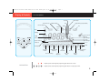
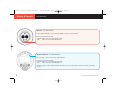
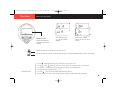
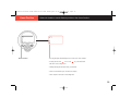
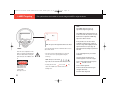
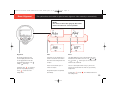
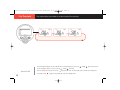
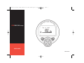
0044-003-04 User Guide:0044-003-01 User Guide.qxd
01/11/2007
12:37
Page 1
FIRERAY 5000 range
USER GUIDE
0044-003-04
0044-003-04 User Guide:0044-003-01 User Guide.qxd
01/11/2007
12:37
Page 2
IMPORTANT
PLEASE NOTE: The beam path MUST be kept clear of
obstructions at all times!
Failure to comply may result in the Detector initiating a Fire or
Fault signal.
NOTE: The word ‘Fire’ will be flashed on the System Controller
when a Fire is detected.
In addition, the Detector number and Fire symbol will flash until
any key is pressed.
0044-003-04 User Guide:0044-003-01 User Guide.qxd
Introduction
01/11/2007
12:37
Page 3
This guide details the setting up & operation of the Fireray 5000 range of beam smoke detectors
CONTENTS
Page 1
Quick Start.
Page 2
Display & Controls - Icons.
Page 3
Display & Controls - LED Indicators.
Page 4
How to use this Guide.
Page 5/6
Viewing Menu - Main operation menu, providing ‘read only’ access to operating parameters.
Page 7
Enter Pass Code - To gain access to the Settings Menu.
Page 8
Settings Menu - Main programming menu, providing access to adjust operating parameters.
Page 9
Detector Settings.
Page 10
Home Position.
Page 11
LASER Targeting.
Page 12
Beam Alignment.
Page 13
Fire Threshold.
Page 14
Fire / Fault Delay.
Page 15
Fire Test.
Page 16
Software Utilities.
Page 17
Controller Settings.
Page 18
Operating Parameters.
Page 19/20
Error Codes - Explanations and Trouble Shooting.
Page 21
Appendix A - Fireray 5000 (Conventional)
Page 22
System Controller wiring diagram.
Page 23
Operational Parameters
0044-003-04 User Guide:0044-003-01 User Guide.qxd
01/11/2007
12:37
Page 4
0044-003-04 User Guide:0044-003-01 User Guide.qxd
Mount and
cable to all
12:37
Page 5
A quick start guide to install a Detector system
Quick Start
START
01/11/2007
Apply power to
system and wait
40 seconds for
Detector to
power up.
Enter Pass Code
Select current
Select Detector to
Set Distance *
Set Home Position
(Factory default
operating mode Hi
be installed
(default 8-50m)
(See page 10)
1234)
or Lo (default Lo)
(only No.1 at
(See page 5)
(See page 7)
(See page 17)
hardware.
present)
(See page 9)
DO NOT
MOUNT
REFLECTOR
A
B
C
D
E
F
G
H
I
J
K
L
DANGER
LASER RADIATION - AVOID
DIRECT EYE EXPOSURE
POWER OUTPUT < 5mW
CLASS IIIa LASER
Wavelength 630 - 680 nm
Select LASER
Mount Reflector. *
Targeting
(As close to
(See page 11)
LASER position as
Manually Steer
LASER to reflector
Auto optimise
Set Zero / 100%
(See page 12)
(See page 9)
(See page 11)
possible)
* NOTE: FOR INSTALLATION OF 8-18m, PLEASE USE THE ENCLOSED SHORT RANGE MASK. PEEL OFF THE WHITE BACKING
COVER TO REVEAL ADHESIVE SURFACE AND PLACE SQUARELY ON TO THE STANDARD 10cm X 10cm REFLECTOR.
(See detector install guide for more details)
1
0044-003-04 User Guide:0044-003-01 User Guide.qxd
01/11/2007
12:37
Page 6
0044-003-04 User Guide:0044-003-01 User Guide.qxd
Display & Controls
01/11/2007
12:37
Page 7
Icon descriptions
Seconds
Latched / Reset
Signal Strength
User Prompt
Signal Clarity (Compensation)
Feet
Detector Number
Degrees
Fire
Metres
Busy
Warning
Key Present
4 Digit
TICK
CROSS
UP
Transmit /
Signal Strength
Numeric Display
Received /
Signal Strength
System Locked/
Unlocked
LEFT
%/V
RIGHT
Cursor
Bar Graph
DOWN
Set Home
Position
LASER Assisted
Targeting
Detector Settings
Beam
Alignment
Fire
Threshold
Fire/ Fault
Delay
System Controller
Settings
Fire Test
Software
Utilities
• Graphic symbols used throughout programming guide indicate Tick & Cross.
NAVIGATION
• Graphic symbols used throughout programming guide indicate Left, Right, Up & Down.
2
0044-003-04 User Guide:0044-003-01 User Guide.qxd
Display & Controls
01/11/2007
12:37
Page 8
LED Indicators
Detector - Two LED indicators:
Health - GREEN LED flashes every 10 seconds indicating the beam is in normal operation.
Status - Red / Yellow Bi-Colour LED:
- YELLOW flashes every 10 seconds indicating a Fault.
- RED
flashes every 10 seconds indicating a Fire.
2.
1.
3.
4.
5.
System Controller - Five LED indicators:
From left to right, 1, 2*, 3* & 4* are Detector Status indicators.
Status - Red / Yellow Bi-Colour LED:
- YELLOW flashes every 10 seconds indicating a Fault.
- RED
flashes every 10 seconds indicating a Fire.
LED 5 is the System Controller status; a GREEN LED flashes every 10 seconds to indicate the System Controller is functioning
correctly.
3
* ONLY AVAILABLE ON MULTI-DETECTOR UNIT
0044-003-04 User Guide:0044-003-01 User Guide.qxd
This Guide
01/11/2007
12:37
Page 9
How to use this guide
Default screens:
Indicated by a bold border
and System Controller Bezel
surround.
When displaying settings,
one or the other would be
displayed.
Screens can be navigated
between and either one of them
selected.
Indicates the system is ‘Locked’ and items may only be viewed.
Indicates the system is ‘Unlocked’, so that values and settings can be altered (A valid Pass Code is required to unlock system).
• The Left
& Right
• The Up
& Down
arrow keys move you between items on the same level.
arrow keys either select items on other levels or change the value of a selected item.
• The Up, Down, Left & Right arrow keys are also used to manually steer the selected Detector.
• Selections are made by pressing the Tick
NAVIGATION
• The Cross
key.
key is used to exit an option without saving any changes.
• Inactivity will cause the system to time-out after 15 minutes in Engineering mode, 30 seconds in User Mode.
4
0044-003-04 User Guide:0044-003-01 User Guide.qxd
Viewing Menu
01/11/2007
12:37
Page 10
This menu allows the operating parameters of the Detector(s) and System Controller to be viewed
Controller parameters
Blank screen - Sleep
is default state of the
display, on pressing any
key the display will wake.
Detector parameters
NAVIGATION
• Pressing Tick
at any point in this menu will prompt for the Pass Code to be entered.
• Pressing Cross
puts the system back into Sleep.
• Navigate screens using the Left
5
Right
Up
& Down
arrow keys.
SCREEN DESCRIPTIONS ON OPPOSITE PAGE
0044-003-04 User Guide:0044-003-01 User Guide.qxd
Viewing Menu
01/11/2007
12:37
Page 11
Screen descriptions
Controller parameters
System Controller Status
Normally good, problems
are indicated by an error
code (See page 19/20).
Current Mode
either Hi A or Lo A
depending on setting
Blank screen - Sleep
is default state of the
display, on pressing any
key the display will wake.
Received signal
strength for the selected
Detector
Compensation
level for selected Detector
NAVIGATION
Status
of selected Detector.
Normally good, problems
are indicated by an error
code (See page 19/20).
Threshold
(sensitivity) for selected
Detector
Temperature
of selected Detector in
either deg C or deg F
dependent
on setting
Distance
of selected Detector as
either 8-50m or 50-100m
• Pressing Tick
at any point in this menu will prompt for the Pass Code to be entered.
• Pressing Cross
puts the system back into Sleep.
• Navigate screens using the Left
Delay
to Fire for selected
Detector
Detector parameters
Scroll
through each Detector in
turn to select other
detectors if fitted *
Software
version of selected
Detector
System Controller
Software version
Right
Up
& Down
Delay
to fault for selected
Detector
arrow keys.
* ONLY AVAILABLE ON MULTI-DETECTOR UNIT
6
0044-003-04 User Guide:0044-003-01 User Guide.qxd
Enter Pass Code
01/11/2007
12:37
Page 12
Allows the Engineer to enter the Pass Code to ‘Unlock’ the system
Prompt
Factory default Pass Code - 1 2 3 4
Detector settings - Is the default screen of the Settings Menu,
which is displayed after the correct Pass Code has been entered.
• Prompt - is accessed by pressing the Tick
key from the User Menu.
• Flashing indicates the current curser position.
• Each digit can be changed by using the Up
• Use the Left
& Right
& Down
arrow keys.
arrow keys to move between digits.
• When all the digits have been set correctly, press the Tick
key. If the Pass Code is correct, the Settings Menu will be displayed.
If the Pass Code is incorrect the display will return to the prompt. After three incorrect attempts, the system will lock access for three
minutes.
NAVIGATION
• Pressing the Cross
key at any time returns the display to the User Menu.
• Note: If no keys are pressed for 30 seconds the system will Lock and ‘Sleep’.
7
0044-003-04 User Guide:0044-003-01 User Guide.qxd
01/11/2007
12:37
Page 13
This menu allows detectors to be installed and settings modified
Settings Menu
2
1
3
4
5
Home Position
Detector Settings
LASER Targeting
Beam Alignment
Fire Threshold
Page 10
Page 9
Page 11
Page 12
Page 13
Page 17
Page 16
Page 15
Page 14
Controller Settings
Software Utilities
Fire Test
Fire / Fault Delay
8
9
6
7
• A valid Pass Code (See page 7) must be entered before any of these functions can be accessed.
• The menu is navigated by the use of the Left
NAVIGATION
of the Tick
& Right
arrow keys, which moves the cursor. Items are selected by the use
key.
• Pressing the Cross
key exits this menu and returns the system to a ‘locked’ state.
8
0044-003-04 User Guide:0044-003-01 User Guide.qxd
Detector Settings
01/11/2007
12:37
Page 14
This option allows the installer to make changes to the Detectors operating parameters
DEFAULT IS FOR NON-LATCHED (RESET)
Set Detector Number *
Set TX Power **
Set Distance
Set Compensation Level **
Auto-Optimise On / Off
Set Fire Latch / Reset
Set RX Gain **
Set Zero / 100%
Pressing the Tick
key stores the
change and returns
to the settings menu.
Pressing the Cross key
ignores any changes
and returns to the
settings menu.
Set Zero / 100%
• This option is selected by pressing the Tick
key.
• Prior to selecting this item ensure the beam is properly aligned and the reflector is uncovered.
• S-00 (Step 0) is displayed, the installer MUST cover the reflector and then press the Tick
NAVIGATION
• S-01 (Step 1) is displayed, the installer can now uncover the reflector and then press the Tick
key whilst it is still covered.
key.
• The system will now return to the settings menu.
9
* ONLY AVAILABLE ON MULTI-DETECTOR UNIT
** ENGINEERING USE ONLY/ WARNING: ALTERING MAY CAUSE MALFUNCTION
0044-003-04 User Guide:0044-003-01 User Guide.qxd
Home Position
Home Position.
01/11/2007
12:38
Page 15
Allows the installer to set the Detector position to the ‘Home Position’.
• Selecting this option automatically steers the motor to the Home Position.
• Pressing either the Tick
or the Cross
key, exits this function
and returns to the settings menu.
• Whilst performing this function the Busy icon will flash.
• Please note this will take up to 15 minutes to complete.
• When complete it will return to the Settings Menu.
10
0044-003-04 User Guide:0044-003-01 User Guide.qxd
LASER Targeting
01/11/2007
12:38
Page 16
This option allows the installer to use the integral LASER to align the beam.
NOTE:
The LASER should be used as an
approximate alignment guide only.
The LASER and the Infrared Beam are not
on the exact same axis, therefore once the
Beam has been aligned the LASER may
appear to be off the reflector.
If not possible to see the laser due to
installation environment (eg, cannot see
NOTE: The system will signal fault while in this mode
reflector or high ambient light) then handalignment must be used (see page 12).
• Selecting this option turns the LASER on and the screen
Auto-alignment must always be performed
above will be shown.
after this.
option, the warning symbol will flash.
• The motor control is enabled and the user may now
To use hand-alignment as part of beam
This is to indicate that selecting this
steer the motor to the required position using the
option will cause the LASER to come
arrow keys.
LASER:
When the cursor is placed over this
installation:
1. Ensure detector and reflector are
on.
mounted opposite in clear line of sight.
NOTE: One press of an arrow
DANGER
LASER RADIATION - AVOID
DIRECT EYE EXPOSURE
POWER OUTPUT < 5mW
CLASS IIIa LASER
Wavelength 630 - 680 nm
11
key results in one movement of the Detector head.
2. Select ‘Auto’ alignment first and press
Cross
• Pressing either the Tick
or the Cross
causes the LASER to turn off and returns to the
Settings menu.
key,
after two seconds.
3. Select ‘Hand’ alignment.
4. Steer beam until the returned signal
strength is above 800.
5. Perform ‘Auto’ alignment.
0044-003-04 User Guide:0044-003-01 User Guide.qxd
Beam Alignment
01/11/2007
12:38
Page 17
This option allows the installer to optimise beam alignment, either manually or automatically.
NOTE:
User must set zero/ 100% (page 9) after either
of these functions for correct operation
Alignment:
Auto:
Hand:
On selecting this option the Auto
This option uses the infrared beam to
This option displays the current returned signal value of the
screen is displayed as shown. This
search for a maximum returned value
infrared beam. The installer can use the; Left
can be toggled between Auto and
and returns to the Settings Menu when
Up
Hand (manual) by using the Left
complete.
maximum value is achieved.
Please note this will take up to 12
There is no auto-repeat function on any key. To move the
minutes to complete.
motor in any given direction more than once, press that key
& Right
Right
arrow keys to steer the motor until a
arrow keys.
Pressing the Tick
key selects the
option currently displayed, pressing
Cross
& Down
returns to the main
Settings Menu.
multiple times.
RX gain and TX power are optimised
automatically.
Pressing Tick
or Cross
when finished returns to the
main settings menu.
12
0044-003-04 User Guide:0044-003-01 User Guide.qxd
Fire Threshold
01/11/2007
12:38
Page 18
This option allows the installer to set the required Fire sensitivity
• The main default settings of 25%, 35% and 50% can be scrolled through by use of the Left
then be changed in steps of 1% by use of the Up
NAVIGATION
• When the desired level has been set, the Tick
• Pressing the Cross
13
& Down
& Right
arrow keys; these can
arrow keys.
key is pressed to save the value and the system returns to the settings menu.
key ignores any change and returns to the Settings Menu.
0044-003-04 User Guide:0044-003-01 User Guide.qxd
Fire / Fault Delay
01/11/2007
12:38
Page 19
This option allows the installer to set the delays for both Fault and Fire independently
Delay 1 (Fire)
Delay 2 (Fault)
On entering this option Delay 1 (Fire) is displayed; Delay 2 (Fault) is accessed by using the Left
& Right
arrow keys, which
toggle between the two delays. It is not possible to set the Delay to Fire to less than the Delay to Fault.
• The value of either delay is adjusted in steps of one second by use of the Up
NAVIGATION
• Pressing the Tick
• Pressing the Cross
& Down
arrow keys.
key saves the current delay values and returns to the settings menu.
key ignores any changes and returns the the settings menu.
14
0044-003-04 User Guide:0044-003-01 User Guide.qxd
Fire Test
01/11/2007
12:38
Page 20
This option places the selected Detector into a fire condition
Confirm screen:
When this screen is displayed the system is waiting for
the user to confirm they wish to perform the test.
Pressing the Tick
key confirms and proceeds
with the test.
Pressing the Cross
key exits without performing
the test with the signal and threshold unchanged.
Fire Test:
Fire screen:
A fire test is performed by the system
The system is now in Fire and the user may press the
overriding the set threshold (sensitivity)
Tick
and setting it to 25%. The signal level
the settings menu.
is then reduced such that the received
signal < 74%, forcing the system into
fire. On exiting this option the signal
level and threshold setting are
returned to their original values.
15
or the Cross
key to exit and return to
0044-003-04 User Guide:0044-003-01 User Guide.qxd
Software Utilities
01/11/2007
12:38
Page 21
This option enables communication with the diagnostic port
On selecting this option the
Exit this option by pressing either the
diagnostics port is enabled and
Tick
communication is possible with the
return to the settings menu.
or the Cross
key and
interface application. ***
*** PC BASED SOFTWARE AVAILABLE AS AN OPTION
16
0044-003-04 User Guide:0044-003-01 User Guide.qxd
Controller Settings
01/11/2007
12:38
Page 22
This option provides access to the System Controller’s operational settings
Current Mode
Units of Measurement
LEFT/ RIGHT - Current Mode, Units of Measurement and
Change Pass Code
Change Pass Code are accessed by using the
Left
& Right
arrow keys.
Pressing the Tick
key stores the
change and returns
to the settings menu.
Pressing the Cross key
ignores any changes
and returns to the
settings menu.
WARNING
Care must be taken when
changing the Pass Code. If lost
the unit can not be unlocked
and must be returned to the
manufacturer. This is not
covered by the warranty.
17
• Current Mode - Sets the system into either high or low operating current mode.
• Units of Measurement - Changes the units of measurement.
• Change Pass Code - Press the Tick
digit is accessed by the Left
• Pressing the Tick
• Pressing the Cross
& Right
key on the Pass Code screen to accesses the option to change the system Pass Code. Each
arrow keys, the value of each digit being altered by the Up
key commits the new Pass Code and returns to the settings menu.
key ignores any change and returns to the settings menu.
& Down
arrow keys.
0044-003-04 User Guide:0044-003-01 User Guide.qxd
Operating Parameters
01/11/2007
12:38
Page 23
Range and effect
Mode
Parameter
Default
Pass code
User Code required to access settings
1234
Current Mode
Hi: the system will draw a constant maximum for configuration
LO
Compensation
Range –50 to +205. Default value 0 on auto optimise This is used by the
Lo: The system will draw a constant minimum for configuration
0
system to amplify the signal, compensating for dust build-up and building
movement. At 100 auto align is invoked
Transmit power
Range 50 to 4095. Sets the intensity of the IR LED.
Received Gain
Range 1 to 255. Sets the received signal amplification from the IR receiver.
Fire Threshold
Range 10% to 60%. Sets the amount the signal needs to fall by to signal a
The higher the value the greater the intensity. Set automatically (by auto-optimise).
The higher the value the greater the gain. Set automatically (by auto-optimise).
35%
fire where 10% is the most sensitive. i.e. a setting of 35% means
the signal needs to fall to or below 65% to be a fire
Delay to Fire
Range 2s to 30s. Sets the time the system needs to be below the
10 seconds
fire threshold before a fire signal is sent to the fire panel.
Delay to Fault
Range 2s to 30s. Sets the time the system needs to be below the
10 seconds
13% before a rapid obscuration fault is sent to fire panel. Note the signal
needs to fall to <=13% within 2s
Distance
8m-50m or 50m-100m. Sets the beam operating length. Effects initial
8-50
transmit power at start of auto optimise
Auto align
Disables or enables auto align.
ON
Latched/non-latched
Sets if the system will latch into a fire when one is detected.
Non-latching
Faults are always non-latching.
18
0044-003-04 User Guide:0044-003-01 User Guide.qxd
Error Codes
01/11/2007
12:38
Page 24
A list of error codes for the Detector and System Controller, explanations & trouble shooting
E-01 DETECTOR NOT FOUND
E-02 NO VALID SERIAL NUMBER
E-03 EEPROM Write
E-08
The System Controller can not locate a
Detector at the selected number.
This is also shown during power up.
The Detector serial number is not valid, there
is a potential fatal error with the Detector.
There was an error writing to the EEPROM.
Compensation has not been set to default of
zero.
Pointers:
Pointers:
Pointers:
Pointers:
• Wait 45 seconds for system power up
• Contact manufacturer.
• Power down system for 1 Minute.
• Ensure peelable mask is removed from
detector First fix
• Check wiring.
19
• If error code seen again call manufacturer.
• Re-align beam using auto-optimise.
0044-003-04 User Guide:0044-003-01 User Guide.qxd
Error Codes
01/11/2007
12:38
Page 25
A list of error codes for the Detector and System Controller, explanations & trouble shooting
E-09
E-10 REFLECTOR NOT FOUND
E-11 AUTO-OPTIMISE FAILED
E-12 CAN’T ZERO
Received signal strength out of range.
The beam can not align onto the reflector,
retry LASER targeting or manual alignment.
The routine timed out whilst trying to maximise
signal strength, the reflector may have been
obscured.
The reflector was not properly covered or the
beam is not aligned onto the reflector.
Pointers:
Pointers:
Pointers:
Pointers:
• Ensure correct distance has been set.
• Ensure correct distance has been set.
• Ensure correct distance has been set.
• Ensure correct reflector type has been used.
• Ensure correct reflector type has been used.
• Ensure correct reflector type has been used.
• Re-align beam using auto-optimise.
• Ensure clear line of sight to reflector.
• Ensure clear line of sight to reflector.
• Re-align beam using auto-optimise.
• Re-align beam using auto-optimise.
• Ensure reflector was uncovered when
‘set’ was selected.
• Ensure reflector was covered with a
non-reflecting material.
20
0044-003-04 User Guide:0044-003-01 User Guide.qxd
01/11/2007
12:38
Page 26
Appendix A
IMPORTANT
PLEASE NOTE: Appendix A contains specific technical details
relating to Fireray 5000 (Conventional) units only.
21
0044-003-04 User Guide:0044-003-01 User Guide.qxd
01/11/2007
12:38
Page 27
FR5000 Wiring Diagram for Single & Multiple Systems on a Zone
Wiring Diagram
TO THE
DETECTOR
CON C
GND
DET 3
SIG
SCN
GND
DET 2
SIG
SCN
GND
SIG
DET 1
SCN
GND
DET 4
SIG
SCN
GND
DET 3
SIG
SCN
GND
DET 2
SIG
SCN
GND
SIG
SCN
GND
SIG
SCN
DET 1
TO THE
DETECTOR
DET 4
CON C
14V TO 28V
DC
14V TO 28V
DC
+
+
-
FIRE
CON A
CON B
N/C
SCN
3
COM
2
N/O
1
SCN
5
CON D
N/C
4
CON B
SCN
COM
3
N/O
2
SCN
1
SCN
FAULT
CON A
CON D
N/C
5
FIRE
SCN
N/C
SCN
4
COM
COM
3
N/O
N/O
2
SCN
SCN
1
-
SCN
FAULT
4
5
1
2
3
4
5
EOL
FIRE RESISTOR
TO THE
FIRE
PANEL
FIRE RESISTOR
ZONE ZONE +
SUPPLY +
SUPPLY SCREEN
Wiring for for all other beams (multi beam system).
Wiring for single or last beam on a Zone.
Please Note:
• The operation for Fire and Fault should always be checked for correct connection to the fire panel.
• Contact the Fire Panel manufacturer for the values of the ‘Fire Resistor’ and the End Of Line component (EOL).
22
0044-003-04 User Guide:0044-003-01 User Guide.qxd
Operational Parameters
01/11/2007
12:38
Page 28
European approval/ operational information
Operational parameters
Typical Operation (1x Detector, System Controller and Conventional AIM): All figures are quoted for 25 deg C.
Parameter
Operating Voltage (to System Controller)
Min
Typ.
Max
Unit
14
-
28
VDC
Approximate Dimensions:
Description
Depth
Weight
mm
Width
mm
Height
mm
kg
Operating Current - low current mode
8
10
12
mA
System Controller, including base
200
235
71
0.9
Operating Current - high current mode
48
50
52
mA
Detector, including 'easy fit' base
134
135
134
0.5
0.45
-
3.98
dB
Universal Bracket
134.1
134.1
70.5
0.2
10
-
60
%
Reflector (Single)
100
100
9.5
0.07
Delay to Fire - user settable (Default 10 sec)
2
-
30
sec
Protective Cage
Ø136
157
-
0.125
Delay to Fault - user settable (Default 10 sec)
2
-
30
sec
Response Threshold/ Sensitivity (Default 35%)
Operating distance (separation) *
8
-
100
m
LED Indication:
Maximum angular misalignment of Detector from optical axis
-
-
± 0.3
Deg
Detector
Maximum angular misalignment of Reflector from optical axis
-
-
±5
Deg
Maximum angular alignment
-
-
±3.5
Deg
-
-
Optical wavelength
Fault level/ Rapid obscuration (< = 2 sec)
850
%
-20
-
+55
Storage temperature
-40
-
+85
Deg C
Relative humidity (non condensing)
-
-
93
%
54
Deg C
-
Contact Voltage - Fire & Fault relays (DPCO)
0.1
-
36
VDC
Contact Current - Fire & Fault relays (DPCO)
0.1
-
500
mA
Cable length - System Controller to Detector
1
-
100
m
24
-
14
AWG
0.5
-
1.5
mm
Cable gauge (2 core screened fire resistant)
Housing flammability rating
UL94 V0
• Status LED - When the beam is in Fault the LED will flash yellow every 10 seconds or red every 10 seconds when
nm
87
Operating temperature
IP rating
• Health LED - When the beam is in normal operation the LED will flash green every 10 seconds
it is in Fire.
System Controller
• Detector Status LEDs (LED 1,2,3 and 4 reading from left to right) - Flash every 10 seconds mimicking the respective
Detector status LED.
• Health LED (LED 5) - When the System Controller is functioning correctly the LED flashes green every 10 seconds.
European Approval Information:
0832
Fire Fighting Enterprises Ltd, 9 Hunting Gate, Hitchin, SG4 0TJ
07
* 1 Reflector & mask required for 8-18m operation. 1 Reflector required for 18-50m operation.
4 Reflectors required for 50-100 m operation.
0832-CPD-0565
EN54-12
Line detector using an optical beam
Fire Saftey
Documentation: See doc. 0044-003
Complies with EN54-12 for sensitivity levels between 25% and 35% with a maximum delay to fire of 20 seconds.
Protective cage must be fitted to comply with EN54-12.
23
0044-003-04 User Guide:0044-003-01 User Guide.qxd
Operational Parameters
01/11/2007
12:38
Page 29
American approval/ operational information
Operational parameters
Typical Operation (1x Detector, System Controller and Conventional AIM): All figures are quoted for 25 deg C.
Parameter
Operating Voltage (to System Controller)
Min
Typ.
Max
Unit
14
-
28
VDC
Approximate Dimensions:
Description
Depth
Weight
in
Width
in
Height
in
lbs
Operating Current - low current mode
8
10
12
mA
System Controller, including base
7.87
9.25
2.80
1.98
Operating Current - high current mode
48
50
52
mA
Detector, including 'easy fit' base
5.28
5.31
5.28
1.10
0.45
-
3.98
dB
Universal Bracket
5.28
5.28
2.78
0.44
10
-
60
%
Reflector (Single)
3.94
3.94
0.37
0.15
Delay to Fire - user settable (Default 10 sec)
2
-
30
sec
Delay to Fault - user settable (Default 10 sec)
2
-
30
sec
Operating distance (separation) *
8
-
100
m
Maximum angular misalignment of Detector from optical axis
-
-
± 0.3
Deg
Maximum angular misalignment of Reflector from optical axis
-
-
±5
Deg
Maximum angular alignment
-
-
±3.5
Deg
nm
LED Indication:
Fault level/ Rapid obscuration (< = 2 sec)
-
-
87
%
Detector
Operating temperature
0
-
+37.8
Deg C
• Health LED - When the beam is in normal operation the LED will flash green every 10 seconds
Storage temperature
-40
-
+85
Deg C
Relative humidity (non condensing)
-
-
93
%
Response Threshold/ Sensitivity (Default 35%)
Optical wavelength
850
IP rating
54
0.1
-
30
VDC
Contact Current - Fire & Fault relays (DPCO)
0.1
-
500
mA
Cable length - System Controller to Detector
1
-
100
m
24
-
14
AWG
-
1.5
mm
0.5
Housing flammability rating
Due to the self-aligning characteristics of this product no maintenance is required. However it is recommended that the
detector lenses be cleaned periodically with a soft lint-free cloth.
• Status LED - When the beam is in Fault the LED will flash yellow every 10 seconds or red every 10 seconds when
it is in Fire.
-
Contact Voltage - Fire & Fault relays (DPCO)
Cable gauge (2 core screened fire resistant)
Maintenance Requirements:
UL94 V0
* 1 Reflector & mask required for 8-18m operation. 1 Reflector required for 18-50m operation.
4 Reflectors required for 50-100 m operation.
Note: The auto-aligning characteristics of this device will reduce the need for maintenance, although a regular inspection
and testing regime should still be implemented to ensure trouble free use of the product.
System Controller
• Detector Status LEDs (LED 1,2,3 and 4 reading from left to right) - Flash every 10 seconds mimicking the respective
Detector status LED.
• Health LED (LED 5) - When the System Controller is functioning correctly the LED flashes green every 10 seconds.
USA Approval Information:
Distance between detector & reflector
Fire Threshold Range
8m -10m - (26.2-32.8ft)
10% - 18%
10m - 15m - (32.8ft - 49.2ft)
15% - 25%
15m - 22m - (49.2ft - 72.2ft)
15% - 35%
22m - 40m - (72.2ft - 131.2ft)
25% - 50%
40m - 60m - (131.2ft - 196.8ft)
35% - 50%
60m - 100m - (196.8ft - 328.1ft)
50%
24
0044-003-04 User Guide:0044-003-01 User Guide.qxd
Notes
01/11/2007
12:38
Page 30
0044-003-04 User Guide:0044-003-01 User Guide.qxd
01/11/2007
12:38
Page 31
0044-003-04 User Guide:0044-003-01 User Guide.qxd
01/11/2007
12:38
Page 32