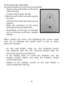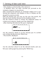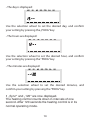
1
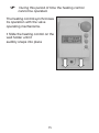
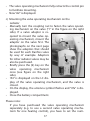
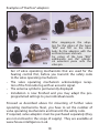
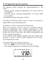
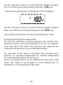
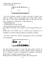
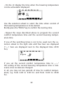
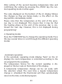
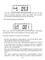
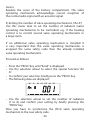
Modbus Guide UG6.70C
Product
HouseHeat
House Heat Wireless Radiator Control Set
User Guide
Online store: www.syxthsense.com
Enquiries: T: 0870 20 80 100 F: 0870 20 80 200
UG6.70C
Table of Contents
Page
1. Intended use......................................................................................... 5
2. Scope of supply.................................................................................... 6
3. General information........................................................................... 7
4. Safety instructions.............................................................................. 9
5. Inserting the batteries into the “FHT80B”
heating control...................................................................................10
6. Wall mounting of the “FHT80B“ heating control....................11
7. Setting of date and time.................................................................13
8. Mounting the “FHT8V” valve operating mechanism ...........16
9. Programming the system...............................................................19
a) Setting of comfort temperature and
lowering temperature.....................................................................19
b) Setting/changing the week profile........................................20
c) Modes of operation.....................................................................23
d) Key lock (for keys and selection wheel)...............................25
e) Switching between comfort temperature and
lowering temperature.....................................................................25
f ) Heating pause................................................................................25
g) Closing the valve..........................................................................26
h) Emergency operation of the
valve operating mechanism..........................................................27
10. Special functions.................................................................................28
11. Replacing of batteries........................................................................40
a) “FHT80B” heating control...........................................................40
b) “FHT8V” valve operating mechanism....................................41
12. Troubleshooting..................................................................................42
13. Handling.................................................................................................43
14. Maintenance and cleaning..............................................................43
3
15. System range information...............................................................44
16. Technical data . ....................................................................................46
17. Disposal..................................................................................................47
4
1. Intended use
The entire radio-controlled radiator thermostat system
comprises two components:
• the “FHT80B” heating control, and
• the “FHT8V” valve operating mechanism
The system is used for temperature control in single rooms
where the heat that dissipates from the radiators is controlled by reducing the flow of hot water in the heating system.
The “FHT80B” heating control measures the room temperature
by means of an integrated sensor and transmits the corresponding control data to the “FHT8V” valve operating mechanisms.
Any other use (e.g. in cooling systems, floor heating systems, etc.) is not permitted and may lead to severe damage.
5
2. Scope of supply
•
•
•
•
“FHT80B” heating control
Wall-mounting set for heating control (screws & dowels)
“FHT8V” valve operating mechanism
Operating instructions
6
3. General information
Compared with simple mechanical thermostats the radiocontrolled radiator thermostat system has a number of advantages:
• the separation into radiator-mounted valve operating mechanisms and freely positionable operation and control units
(e.g. the “FHT80B” heating control which is part of the scope
of supply) makes it possible to perform settings easily.
• the programming option makes it possible to adapt the
system to the lifestyle of its users, so that the room is always comfortably warm when it is used. When the room
is not used, the temperature may be reduced automatically to save energy, i.e. the often cumbersome manual
opening and closing of heating valves is no longer required.
• The system is equipped with an integrated calcification
protection. Once every week (time can be set) the valve
operating mechanism opens and closes the valve to prevent blocking of the valve by lime deposits.
a) Operating principle
In the “FHT80B” heating control the room temperature is measured and compared to the desired temperature (set either by
means of the time program or manually).
The difference is used to calculate how far the valve has to
be opened or closed to obtain the desired temperature. In
a time interval of approx. two minutes commands are radio-transmitted to the “FHT8V” valve operating mechanism
mounted on the radiator. This valve operating mechanism
then reduces or increases the heat.
Heating up of a room takes some time, depending on the size
7
of the radiators. If the desired temperature is changed, the room
temperature changes with a certain delay. Deviations between
the desired value and the room temperature may also be caused
by various disturbance variables, e.g. draughts, other sources of
heat in the room, or an insufficient supply of heat by the heating
boiler. Temperature measurement within the control is very exact (deviation <1K). To avoid any unnecessary operation of the
valve, e.g. when the room temperature changes temporarily because a door is opened, the measured values of several measurements are averaged.
b) Safety code
The radio signal is protected by a safety code consisting
of two parts. This safety code protects the system against
interference from other radiosystems and ensures that several radio-controlled radiator thermostat systems can be
operated separately in a household. Each part of the code
comprises 100 setting options. This means that there are
10,000 different safety codes available. To ensure communication between the heating control and the valve operating mechanism/s the same safety code has to be set for all
devices in a room.
Ex works the set consisting of heating control and valve
operating mechanism is protected by a randomly assigned safety code, the valve operating mechanism is
preset to the safety code of the heating control. If you
want to use additional valve operating mechanisms on
one heating control (maximum number is 8) the number of valve operating mechanisms has to be set on the
heating control, and the safety code has to be transmitted to the valve operating mechanism.
8
4. Safety instructions
The warranty will lapse for damage due to non-compliance with these operating instructions. We shall
not be held liable for any consequential damage
or loss! We shall not accept liability for damage to
property or personal injury caused by incorrect handling or non-compliance with the safety instructions.
Any claim to warranty will lapse in such cases.
a) General
Do not use this product in hospitals or medical institutions.
The product does only emit relatively weak radio signals.
These radio signals could, however, lead to malfunctions in
life-supporting systems. The same may possibly apply
to other areas.
The product must only be used in dry indoor areas, it must
be protected from moist and water.
The product is not a toy and must be kept out of the reach
of children.
For safety and licensing (CE) reasons, unauthorised conversion of and/or modifications to the product are not permitted.
Do not leave the packaging material lying around carelessly.
Plastic film and/or bags, polystyrene parts, etc. can be dangerous in the hands of children.
Handle the product with care. It can be damaged through
impact, blows, or by being dropped even from a low
height.
b) Batteries and accumulators
• Keep batteries/accumulators out of the reach of children.
• Make sure to insert the batteries/accumulators with the
9
correct polarity.
• Do not leave the batteries lying around in the open; there
is a risk of them being swallowed by children or pets. If
swallowed, immediately contact a doctor.
• Leaking or damaged batteries/accumulators may cause
burning if they come into contact with the skin. For this
reason you should use suitable protective gloves when
handling batteries.
• Do not short-circuit batteries/accumulators, and do not
throw batteries/accumulators into a fire. There is a risk of
explosion!
• Do not disassemble batteries/accumulators!
• Do not recharge normal batteries. There is a risk of explosion!
• In case of longer periods of non-use (e.g. during storage) remove the inserted batteries/accumulators to avoid
damage by a leaking battery/accumulator.
5. Inserting the batteries into the
„FHT80B“ heating control
• Slide down and remove the wall holder on the back of the
heating control.
• Slide down and remove the cover of the battery compartment (in direction of the imprinted arrow on the cover).
• Insert two AA batteries; pay attention to the correct polarity. Look into the battery compartment for an illustration of the correct polarity.
We recommend to use high-quality alkaline batteries
only. Operation of the heating control using accumulators or conventional zinc-carbon batteries is possible,
operating time and radio range of the heating control
will, however, be reduced.
10
Furthermore, there will be a risk of malfunctions.
Make sure to insert the batteries correctly to avoid
damage to the electronic components of the heating control.
• Close the battery compartment.
• The heating control performs a short display test. After
the display test, you have to set date and time).
• If the battery symbol (“
“) is displayed on the LC display, the battery voltage is low and the batteries should
be replaced as soon as possible.
The same applies, if the radio range decreases or if data are
no longer displayed on the LC display.
6. Wall mounting of “FHT80B“
a) Choosing an appropriate mounting location
Make sure to choose an appropriate location for mounting the
“FHT80B” heating control. This has to meet the following requirements:
• central position in the room where the temperature is to
be controlled
• easy access for convenient operation
• mounting at eye level for easy reading of the display
• no mounting on a badly insulated outer wall
• no direct sunlight
• no interference from heat sources such as radiators, TV
sets, lamps, refrigerators,etc.
• no mounting next to a window
• greatest possible distance to metal objects to avoid any
unnecessary reduction of the operating range
11
b) Mounting the wall holder
Proceed as follows to mount the wall holder:
• Remove the wall holder on the back
of the heating
control, slide it down for this.
• Place the wall holder vertically against
the wall
with the round side pointing up (see
picture).
• Mark the positions of the bores
through the two slotted holes.
• Depending on the type of wall drill
two 6 mm holes and insert suitable
dowels.
When drilling the bores and tightening the screws make
sure not to damage any power lines or gas or water
pipes, etc.! Danger!
• Fix the wall holder using e.g. the enclosed screws.
Pay attention that the two recessed slotted holes for
the screws point in your direction.
• If not already done so, insert the batteries into the
heating control before you slide the heating control
on the wall holder.
• Sliding of the heating control on the wall holder is
now possible from the top.
12
7. Setting of date and time
• If the display is protected by a foil, remove it.
• If batteries have not been inserted yet, proceed as described in chapter 6 to insert them.
After inserting the batteries an automatic display test is performed (all segments and displays of the LC display are displayed for several seconds).
After the display test you may set the year, the month, the
day, the hours and the minutes on the heating control.
Use the selection wheel to change the displayed values. To
confirm your selection, briefly press the “PROG” key.
• After inserting the batteries the year is displayed:
M�O�
DI�
M�I�
DO� F�R� S�A�
S�O�
P�r� o� g�
6�
0�
1�2�
1�8�
2�4�
Use the selection wheel to set the desired year. To confirm
your setting, briefly press the “PROG” key.
• The month is displayed:
MO
0
DI
MI DO FR SA SO
6
12
18
24
Use the selection wheel to set the desired month, and confirm your setting again by pressing the “PROG” key.
13
• The day is displayed:
MO
DI
MI
DO FR SA
12
6
0
SO
24
18
Use the selection wheel to set the desired day, and confirm
your setting by pressing the „PROG” key.
• The hours are displayed:
MO
DI
MI
12
6
0
DO FR SA
SO
24
18
Use the selection wheel to set the desired hour, and confirm
your setting by pressing the “PROG” key.
• The minutes are displayed:
MO
0
DI
MI
6
DO FR SA
12
18
SO
24
Use the selection wheel to set the desired minutes, and
confirm your setting by pressing the “PROG” key.
• „Sync“ and „120“ are now displayed.
The heating control counts down in intervals of one
second. After 120 seconds the heating control is in its
normal operating mode.
14
During this period of time the heating control
cannot be operated.
The heating control synchronises
its operation with the valve
operating mechanisms.
• Slide the heating control on the
wall holder until it
audibly snaps into place
15
8. Mounting the „FHT8V“
valve operating mechanism
a) Removing the old thermostat
• Remove the old mechanical thermostat.
• If necessary, use multigrip pliers
to loosen seized screws by turning
them counterclockwise.
b) Inserting the the batteries into the
valve operating mechanism
• Remove the battery compartment
cover of the valve operating mechanism by sliding it down.
• Insert two AA batteries into the
battery compartment.
Make sure to insert the batteries
with the correct polarity, see illustration in the battery compartment and
figure on the right side.
• “C1” is displayed first, followed by a
twodigit number, “C2”, and another two-digit number. These two
numbers are the currently stored
safety code of the valve operating
mechanism (e.g. 11 and 22 = safety code 1122).
• An acoustic signal is generated,
and “A1” is displayed.
16
• The valve operating mechanism fully retracts the control pin
to facilitate mounting.
• Now “A2” is displayed.
c) Mounting the valve operating mechanism on the
radiator
• Manually turn the coupling nut to fasten the valve operating mechanism on the valve (“1” in the figure on the right
side). If a valve adaptor is required to mount the valve operating mechanism, mount the
adaptor on the valve first. The
photographs on the next page
show the adaptors that should
be used for each Danfoss valve
by way of example. Adaptors
for other radiator valves may be
also be purchased.
• Briefly press the (2) key on the
valve operating mechanism
once (see figure on the right
side).
• “A3” is displayed on the LC display of the valve operating mechanism, and the valve is
closed.
• On the display, the antenna symbol flashes and “0%” is displayed.
• Close the battery compartment.
Please note:
If you have purchased the valve operating mechanism
separately (e.g. to use a second valve operating mechanism for one heating control), you have to set the num17
Examples of “Danfoss” adaptors:
RA
RAVL
After snapping-on the adaptors for the valves of the types
“RAV” and “RA” on the valve
body fix the adaptors with the
enclosed screws and nuts.
For valves of the type “RAV”
additionally put the cylindrical extension piece onto the
valve pin.
RAV
ber of valve operating mechanisms that are used for the
heating control first, before you transmit the safety code
to the valve operating mechanism.
• The valve operating mechanism acknowledges reception of the first radio log with an acoustic signal.
• The antenna symbol is permanently displayed.
• Installation is now finished and you may adapt the preprogrammed settings to your individual needs.
Proceed as described above for mounting of further valve
operating mechanisms. Next, you have to set the number of
valve operating mechanisms and transmit the safety code .
If required, valve adaptors must be purchased separately (they
are not enclosed in the scope of supply). They are available at
www.house-intelligence.co.uk.
18
9. Programming the system
All required system settings are preprogrammed in the
works:
• Heating phase: Comfort temperature 21°C from 6.00 hrs
to 23.00 hrs
• Lowering phase: Lowering temperature 17°C from 23.00
hrs to 6.00 hrs
• Decalcification cycle: Saturday, 11.00 hrs
All settings mentioned above may of course be changed to
adapt them to your individual needs.
a) Setting of comfort and lowering temperatures
When the automatic mode is active (i.e. switching between
lowering temperature and comfort temperature is performed automatically), a bar in the display’s bottom part indicates the time of day when the desired temperature will
be the comfort temperature.
A sun symbol on the display indicates that the comfort temperature is active; a moon symbol indicates that the lowering temperature is active.
Proceed as follows to change the settings:
• Press the “
“ key for more than 3 seconds.
• The comfort temperature is displayed on the LC display.
MO
DI
MI DO FR SA SO
C
0
6
12
19
18
24
Use the selection wheel to set the desired comfort temperature. To confirm your setting, briefly press the „
„ key.
• The lowering temperature is displayed on the LC display.
MO
DI
MI DO FR SA SO
C
0
6
12
18
24
Use the selection wheel to set the desired lowering temperature. To confirm your setting, briefly press the „
„ key.
• The heating control returns to the normal operating mode.
b) Setting/changing the week profile
The time for automatic switching between the comfort temperature and the lowering temperature can be set separately for each day of the week. That way you may adapt the desired room temperature to your individual lifestyle.
For each day of the week 4 switching times (comfort temperature on, lowering temperature on, comfort temperature
on, lowering temperature on) can be set.
These 4 switching times can be different for each day of the
week. This makes it e.g. possible to start heating later on
weekends or on certain days of the week.
20
• Briefly press the “PROG” key.
• “Prog” is displayed
MO
DI
MI DO FR SA
SO
Prog
12
6
0
24
18
• Use the selection wheel to select the day for which you
want to change the time program. You may either select
each day of the week individually (MO, DI, MI, DO, FR, SA,
SO) or program a combination of days (block), i.e.:
- weekend (SA, SO)
- weekdays (MO, DI, MI, DO, FR)
- all days (MO, DI, MI, DO, FR, SA, SO)
This option facilitates and speeds up the programming process.
Briefly press the “PROG” key to confirm your selection of a
weekday or a block of days (weekend, weekdays, all days).
• The time when the comfort temperature will be switched
on is displayed:
MO
DI
MI DO FR SA
SO
Prog
0
6
12
18
24
Use the selection wheel to select the time when control of
the comfort temperature is to be started. On the bottom of
the LC display a scale is displayed to facilitate orientation
(long marks = comfort temperature is active).
Briefly press the “PROG” key to confirm the starting time.
21
• On the LC display the time when the lowering temperature
is to be activated is displayed:
DI
MO
MI DO FR SA
SO
Prog
12
6
0
24
18
Use the selection wheel to select the time when control of
the lowering temperature is to be started.
Briefly press the “PROG” key to confirm the starting time.
• Repeat the steps described above to program the second
comfort temperature time and the second lowering temperature time.
If one of the switching times is not to be used, turn the selection wheel to the right side until four bars are displayed
(“--:--”, bars are displayed next to the displayed time 23:50
hrs).
MO
DI
MI DO FR SA
SO
Prog
0
6
12
18
24
If you set the second comfort temperature time to „--:--“
the setting of the second lowering temperature time is irrelevant, since no data are changed.
In all, you may set two periods of time for comfort temperature, e.g. from 6.00 to 9.00 hrs and from 16.00 to 23.00
hrs.
22
After setting of the second lowering temperature time and
confirming the setting by pressing the „PROG” key the normal operating mode is active again.
The scale displayed on the bottom of the LC display follows
the changes as they are being made, i.e. the effect on the
day profile is immediately visible.
Please note that the temperature at the end of the previous day is not displayed. This means that it may be that
the heating phase at the end of the previous day is continued the next day. However, this is not displayed during
programming!
c) Operating modes
Press the “FUNKTION” key to change the operating mode. Press
this key several times to scroll through the different operating
modes.
• Automatic operation
In the automatic operating mode (display “Auto” on the LC
display) the room temperature is controlled according to the
set program for the weekday.
The temperature history for the current weekday is displayed on the bar scale on the bottom of the display.
A temporarily temperature change can be set easily with
the selection wheel. The next time a regular temperature
change is scheduled the thermostat will then automatically
return to the time-controlled program.
23
• Manual operation
In the manual operating mode (display “Manu”) the heating
control maintains the set temperature. An automatic timecontrolled change will not be performed.
This function is identical to the function of a conventional
thermostat.
• Holiday/party function
In this operating mode (display of suitcase symbol) the temperature is kept at a certain fixed value for a defined period of time (e.g. the duration of a party or a holiday). After
this, the heating control automatically switches to the automatic mode.
Setting the holiday/party function:
• Select this operating mode with the “FUNKTION” key and
set the period of time this function is to be active.
During the following 24 hours the temperature will be reduced every 30 minutes (party function). After 24 hours the
temperature will be reduced every day (holiday function).
Set the day you will return from your holidays. As of this day
and starting at 0.00 hrs heating will be performed with the
normal time program.
• Confirm your setting of the desired period of time by briefly pressing the “PROG” key.
• Use the selection wheel to set the desired temperature.
If you select a different operating mode with the “FUNKTION” key, you will automatically quit the holiday/party
mode.
24
d) Key lock (for keys and selection wheel)
The heating control is equipped with an integrated key lock
for the keys and the selection wheel, to protect the device
from unintentional operation (i.e. by children).
Activating the key lock
• To activate the key lock, simultaneously press the keys
“FUNKTION” and “PROG”.
• “LOC” is displayed briefly on the display, all operating
functions are blocked.
Deactivating the key lock
• To deactivate the key lock, simultaneously press the two
keys “FUNKTION” and “PROG” until “LOC” is no longer
displayed (after about 2 seconds).
• All operating functions are available again.
e) Switching between comfort temperature and
lowering temperature
If a room is used at different times than set in the time program you may change the temperature any time using the
selection wheel.
You may also switch directly from comfort temperature to
lowering temperature by pressing the “
“ key.
f ) Heating pause
Switching off the heating during the summer saves battery
energy and prolongs the service life of the batteries.
During the heating pause the valve is opened completely
and remains in this position. The weekly decalcification cycle will, however, still be performed.
25
Proceed as follows to activate the heating pause:
• Press the “FUNKTION” key to switch to the operating
mode “Manu”.
• Turn the selection wheel clockwise until “On” is displayed
on the LC display.
MO
DI
MI
DO FR SA
SO
Manu
12
6
0
24
18
g) Closing the valve
Select this operating mode if the room is not to be heated at all.
The valve is closed and remains closed.
The valve is only opened if the temperature drops below
5°C (danger of freezing). The weekly decalcification cycle
will still be performed.
Proceed as follows.
• Press the “FUNKTION” key to switch to the operating
mode “Manu”.
• Turn the selection wheel counterclockwise until “OFF is
displayed on the LC display.
MO
DI
MI
DO FR SA
SO
Manu
0
6
12
26
18
24
h) Emergency operation of the valve operating
mechanism
If an error occurs that cannot be rectified immediately (e.g. because the
battery voltage of the heating control or valve operating mechanism
is low and new batteries are not at
hand) it may be necessary to operate
the valve manually. To do so, proceed
as follows:
• Remove both batteries from the
valve operating
mechanism.
• Press down the adjusting pin at the
point
marked with (1) and remove it.
• Put the control pin onto the peg marked
with (2).
• Turn the adjusting pin:
- Clockwise = increase heat
- Counterclockwise = reduce heat
27
10. Special functions
The heating control has several special functions.
To open the special functions menu press the “PROG” key
until “Sond” is displayed on the LC display. Then release
the “PROG” key again.
The special functions menu can only be opened if the heating control is in the normal operating mode (time and date
displayed on the left side of the display, temperature displayed on the right side).
The following special functions are available:
(1) CALC Setting the time for the decalcification cycle
(2) °C°F Selecting the temperature unit (°C or °F)
(3) dAt Setting of date and time
(4) CodE Changing the safety code for radio transmission
and setting of codes for new valve operating mech
anisms, respectively
(5) An A Setting the number of valves controlled by the
heating control and extending the system,
respectively
(6) SYnC Synchronising the valve operating mechanisms
(7) tESt Testing of radio transmission
(8) StEL Displaying the valve position
(9) CEnt Integration with FHZ 1000 HouseMaster
(not included)
(10) FEn
Integration for door / windows contact
(Not included)
(11) OFFS Setting the offset (this option is only displayed, if
there is more than one valve operating mecha
nism)
28
1) Setting the decalcification time („CALC“)
Once every week the valve is completely opened and
closed. This prevents blocking of the valve by deposits. The
time at which the decalcification cycle is performed can be
changed using the special function “CALC”.
• Press the “PROG” key until “Sond” is displayed. Then release the “PROG” key again.
• Use the selection wheel to select the special function
“CALC”.
• To confirm your selection, briefly press the “PROG” key.
MO
DI
MI DO FR SA
6
0
12
SO
24
18
• Use the selection wheel to select the weekday.
• Confirm the selected weekday by pressing the “PROG”
key. In the first line of the LC display the time when the
decalcification cycle will be performed is displayed.
MO
0
DI
MI DO FR SA
6
12
18
SO
24
• Use the selection wheel to change the displayed time.
• Confirm the set decalcification time by pressing the
“PROG” key. The heating control returns to the normal
operating mode.
29
2) Selecting the temperature unit (“°C°F”)
You may set whether the temperature is to be displayed in
degrees Celsius (°C) or degrees Fahrenheit (°F).
• Press the “PROG” key until “Sond” is displayed (for special function).
• Use the selection wheel to select the special function
“°C°F”.
• To confirm your selection, briefly press the “PROG” key.
• Use the selection wheel to switch between “°C” and
“°F”.
• To confirm your selection, briefly press the “PROG”
key. The heating control returns to the normal operating
mode.
3) Setting of date and time (“dAt”)
• Press the “PROG” key until “Sond” is displayed.
• Use the selection wheel to select the special function
“dAt”.
• To confirm your selection, briefly press the “PROG” key.
30
4) Setting the safety code (“CodE”)
To protect the heating control against interference from other radio systems the device uses a safety code consisting
of two parts. Each part of the code comprises 100 setting
options. This means that there are 10,000 different safety
codes available.
To ensure communication between the “FHT80B” heating control and the “FHT8V” valve operating mechanism/s the same
safety code has to be set for all devices in a room.
This is particularly important if more than one valve operating mechanism is used or if different devices (i.e.
not a set consisting of heating control and valve operating mechanism) were purchased.
Proceed as follows to change or set the code:
• Press the “PROG” key until “Sond” is displayed.
• Use the selection wheel to select the special function
“CodE”.
• To confirm your selection, briefly press the “PROG” key.
The following data are displayed:
• Use the selection wheel to select the first part of the code
(a number between “000” and “099”) and confirm this selection by briefly pressing the “PROG” key.
• The following data are displayed:
31
• Use the selection wheel to select the second part of the
code (a number between “000” and “099”) and confirm
this selection by briefly pressing the “PROG” key.
• The following data are displayed:
Now you have to synchronise the (first) valve operating
mechanism (“001” on the display) to the new safety code.
Proceed as follows to synchronise the data:
• Remove the battery compartment cover of the (first) valve
operating mechanism by sliding it down.
• Press the key of the valve operating mechanism for about
3 seconds until you hear an acoustic signal (3 separate
tones). The valve operating mechanism is now ready to
receive, “AC” is displayed.
• Press the “PROG” key on the “FHT80B” heating control to start
transmission of the safety code to the valve operating mechanism.
• The valve operating mechanism acknowledges correct
reception of the code with an acoustic signal (sequence
32
of tones).
• Replace the cover of the battery compartment.
• The valve operating mechanism acknowledges the first
reception of a normal radio signal with an acoustic signal.
Repeat these steps for all other valve operating mechanisms in the room (“002”, “003”, etc. on the display).
After encoding of the last valve operating mechanism is finished the heating control automatically returns to the normal operating mode.
If the heating control is used to control several valve operating mechanisms, i.e. if there are several radiators in one
room, you should make a note of the assignment between
valve operating mechanisms and radiators (radiator numbers).
If the encoding of a valve operating mechanism fails (e.g.
due to bad signal reception, low battery voltage, or the
like) transmission of the safety code to this valve operating
mechanism can be repeated at a later time.
• Proceed as described above and skip the valve operating mechanisms that have already been encoded by briefly
pressing the “PROG” key.
• If the LC display shows the number of a valve operating
mechanism that has not received a safety code yet, press
the push-button on this valve operating mechanism until
“AC” is displayed on the valve operating mechanism and
you hear an acoustic signal (3 signal tones).
• Press the “PROG” key on the heating control to initiate
transmission of the safety code by the heating control. The
valve operating mechanism acknowledges correct reception of the code with an acoustic signal (sequence of
33
tones).
Replace the cover of the battery compartment. The valve
operating mechanism acknowledges correct reception of
the normal radio signal with an acoustic signal.
5) Setting the number of valve operating mechanisms (“An A”)
Use this menu item to set the number of radiators (valve
operating mechanisms) to be controlled, e.g. if the heating
control is to control several valve operating mechanisms in
a large room.
If an additional valve operating mechanism is installed it
is very important that this valve operating mechanisms is
assigned the same safety code than the already installed
valve operating mechanisms.
Proceed as follows:
• Press the “PROG” key until “Sond” is displayed.
• Use the selection wheel to select the special function “An
A”.
• To confirm your selection, briefly press the “PROG” key.
• The following data are displayed:
M�O�
0�
DI�
M�I�
6�
DO� F�R� S�A�
1�2�
1�8�
S�O�
2�4�
• Use the selection wheel to set the number of radiators
(1 to 8) and confirm your setting by briefly pressing the
“PROG” key.
Now you have to synchronise the (first) valve operating
mechanism to the new safety code.
34
Repeat the following 6 steps for each installed valve operating mechanism:
1. Remove the battery compartment cover of the (first) valve
operating mechanism by sliding it down.
2. Press the key of the valve operating mechanism for about
3 seconds until you hear 3 signal tones. The valve operating mechanism is now ready to receive, “AC” is displayed.
3. Press the “PROG” key on the heating control to start
transmission of the heating control’s safety code to the
valve operating mechanism.
4. The valve operating mechanism acknowledges correct
reception of the code with a sequence of tones.
5. Replace the cover of the battery compartment.
6. The valve operating mechanism acknowledges the first
reception of a normal radio signal with an acoustic signal.
Repeat these 6 steps for all other valve operating mechanisms in the room (“002”, “003”, etc. on the display) according to the number of valve operating mechanisms set
before.
After encoding of all valve operating mechanisms is finished
the heating control automatically returns to the normal operating mode.
You may skip valve operating mechanisms which are already synchronised/ programmed to the safety code of the
heating control.
For this purpose, just briefly press the “PROG” key on the
heating control (do not open the corresponding valve oper35
ating mechanism/do not press the key on the valve operating mechanism!)
6) Synchronising the valve operating mechanisms
(“SYnC”)
After selection of this menu item the heating control starts
to transmit signals to all valve operating mechanisms for
about 2 minutes instructing them to newly sychronise themselves.
After synchronisation the normal transmission program is
continued and the valve operating mechanisms generate
an acoustic signal the moment they receive the first correct signal.
• Press the “PROG” key until “Sond” is displayed.
• Use the selection wheel to select the special function
“SynC”.
• To confirm your selection, briefly press the “PROG” key.
• The safety code is displayed and the heating control
starts to count down from “120” in steps of 1 second. After these 120 seconds the heating control returns to the
normal operating mode.
7) Test mode (“tESt”)
Use this function to check whether all valve operating
mechanisms receive the radio signal correctly. The tested
valve operating mechanisms acknowledge correct reception with an acoustic signal. Use the selection wheel to select the valve operating mechanisms to be tested.
If the large display shows a “0” (zero), all valve operating mechanisms are tested, otherwise, only the valve operating mechanism assigned to the displayed number is tested. The timer in
the left corner of the display counts down to the point in time
the next test cycle is to be started.
36
• Press the “PROG” key until “Sond” is displayed.
• Use the selection wheel to select the special function
“tEST”.
• To confirm your selection, briefly press the “PROG” key.
• Use the selection wheel to select the valve operating
mechanism/s to be tested.
• Press the “PROG” key to quit the test function.
8) Displaying the valve position (“StEL”)
After selection of this menu item the approximate percentage of the valve opening is displayed on the heating control
(for valve operating mechanism 1 only).
• Press the “PROG” key until “Sond” is displayed.
• Use the selection wheel to select the special function
“StEL”.
• To confirm your selection, briefly press the “PROG” key.
• The display shows the valve opening in percent (“%”).
• Press the “PROG” key to quit the function.
9) Integration with FHZ 1000 HouseMaster (“CEnt”)
This function is only required if the FHT 80B Heating Control is
required to be integrated with a different FHZ 1000 HouseMaster central controller than hitherto or if no integration with any
FHZ 1000 HouseMaster central controller is required.
Wireless communication between the FHT 80B Heating Control
and FHZ 1000 HouseMaster is made secure by use of the unique
security code associated with each FHT 80B Heating Control in
a HouseHeat installation. The FHT 80B Heating Control is ‘registered’ with FHZ 1000 HouseMaster using this code in order to
enable the two products to work together.
In order to ensure that the FHT 80B Heating Controller cannot
37
mistakenly be controlled e.g. by a neighbour’s FHZ 1000 HouseMaster central controller, each FHT 80B Heating Controller may
only be registered to one FHZ 1000 HouseMaster. If it is necessary to register a FHT 80B Heating Controller to a new FHZ 1000
HouseMaster, the FHT 80B Heating Controller must first be deregistered from the original FHZ 1000 HouseMaster. Three different settings are possible:
“On”: FHT 80B is registered to the FHZ1000 HouseMaster
“Off”: No wireless communication occurs between the
FHT 80B and FHZ 1000 HouseMaster. Registration not
possible
“nA”: FHT 80B is available for registration to
FHZ 1000 HouseMaster
Proceed as follows to specify whether the FHT 80B Heating Controller should work together with a FHZ 1000 HouseMaster central controller:
• Press the “PROG” key until “Sond” is displayed.
• Use the selection wheel to select the special function “CEnt”.
• To confirm your selection, briefly press the “PROG” key.
• The display shows the current setting
• Use the selection wheel to select the desired setting (On/Off/
nA)
• Press the “PROG” key to return the FHT 80B to normal operating mode
10 ) Integration with FHT 80TF Door & Window Sensors (“FEn”)
Please consult the documentation supplied with the FHT 80TF
Door & Window Sensor to learn how to set the FHT 80B Heating Controller to work together with FHT 80TF Door & Window
Sensors.
38
11) Radiator offset (“OFFS”)
This setting option is only displayed if you use more than one
valve operating mechanism.
If several radiators are controlled by one heating control, it may
occur that these radiators are not heated up uniformly.
The reason for this is that the flowrates of different valves differ
greatly, depending on different or bad radiator dimensions. This
problem may be solved by adjusting the settings of single radiators in such a way that they give off more (positive offset) or less
(negative offset) heat.
• Press the “PROG” key until “Sond” is displayed.• Use the selec
tion wheel to select the special function “OFFS”.
• To confirm your selection, briefly press the “PROG” key.
• Use the selection wheel to select the desired valve operating
mechanism/radiator, and confirm your selection by pressing
the “PROG” key.
• Use the selection wheel to set the desired offset, and confirm
your setting by pressing the “PROG” key. The heating control
returns to the normal operating mode.
Maybe, this process has to be repeated several times until distribution of the heating power seems to be optimal.
Please note: Setting the offset does not change the displayed
percentage of the valve opening
(valve position). The offset value only influences the slope of the
valve characteristic.
At a control value of 10% given by the heating control a valve
with a positive offset is opened wider than a valve with a negative offset, although the displayed value is 10% for both valves.
39
11. Replacing the battery
a) “FHT80B” heating control
If the battery symbol (“
“) is displayed on the LC display,
the battery voltage is low and they have to be replaced.
In addition, the heating control generates an acoustic alarm
every 2 minutes.
At night the acoustic alarm is not generated, but only during
the following three periods of time:
- from 10.00 hrs to 11.00 hrs
- from 17.00 hrs to 18.00 hrs
- from 21.00 hrs to 22.00 hrs
Proceed as follows to replace the batteries:
• Take the heating control off the wall holder and open the
cover of the battery compartment (slide down).
• Remove the empty batteries from the battery compartment and dispose of them according to applicable environmental regulations
• Insert two new AA batteries; pay attention to the correct
polarity. If possible use alkaline batteries.
• Close the battery compartment.
• Like during first commissioning the heating control asks
you to enter date and time.
• However, the settings of the time program, the comfort/
lowering temperature, etc., have been maintained.
• Since the heating control and the valve operating mechanisms are no longer synchonised after a battery replacement the heating control performs an automatic synchronisation that takes about 2 minutes (“SYnc Auto”).
After the synchronisation the heating control returns to
the normal operating mode.
40
b) “FHT8V” valve operating mechanism
If the batteries of the valve operating mechanism are empty, the battery symbol is displayed. In addition, an acoustic
signal in generated in intervals of 2 minutes for three hours
every day.
Proceed as follows to replace the batteries:
• Remove the cover of the valve operating mechanism’s
battery compartment (slide down).
• Remove the empty batteries and dispose of them according to applicable environmental regulations
• Wait until all segments of the valve operating mechanism’s LC display are off. You may speed up this process
by pressing the key on the valve operating mechanism.
• Insert two new AA batteries into the battery compartment. Pay attention to the correct polarity. If possible use
alkaline batteries.
• The display shows “C1” followed by a 2-digit number,
followed by “C2” and another 2-digit number (both numbers together are the currently stored safety code of the
valve operating mechanism).
• An acoustic signal is generated, and “A1” is displayed.
• The valve operating mechanism fully retracts the control
pin.
• Afterwards “A2” is displayed.
• Briefly press the key on the valve operating mechanism.
• “A3” is displayed and the operating mechanism fully
closes the valve.
• The antenna symbol flashes and “0%” is displayed.
• The first received radio signal is acknowledged by an acoustic
signal, the antenna symbol is permanently displayed.
• Replace the cover of the battery compartment.
41
12. Troubleshooting
Problem
Possible cause
Solution
Permanent tone signal Heavy operation of
Remove valve motor
and display of “F1” on the valve or blocked
Manually check
the valve motor
radiator valve
operations
Re-install
If problem reemerges contact your dealer
Permanent tone signal Valve and adaptor
and “F2” is displayed are not compatible
constantly on the valve motor
Use 1mm gray
extension piece
Permanent tone signal Signal range too Re-install valve
and “F3” is displayed narrow
on the valve motor Unsuitable valve
No antenna symbol displayed on valve motor
Radio connection failure Install heating control
due to interference. in a different location
At an interval of one hour the valve motor generates a sequence
of tones.
The valve opening is
30%
“Low Bat” symbol
displayed Heating control battery
is empty
Replace heating
batteries
Wrong security
Transmit the current
on the room thermostat security code to the
motor valve
Valve motor is all most
42
Replace the
batteries
13. Handling
• Protect the product against humidity, cold, heat, dust,
and direct sunlight.
• Do not disassemble the product. Have any repairs performed by experts, otherwise the license (CE) of the
product will lapse!
• Do not drop the product, it will be damaged even if it
falls from a low height.
14. Maintenance and cleaning
The product does not require any maintenance apart from
replacing of batteries. Clean the product with a soft, clean,
dry and fuzz free cloth. To achieve a better cleaning action
the cloth can be dampened with lukewarm water.
Take care not to let any moisture get into the product!
Do not use cleaning agents containing solvents, since these
may damage the plastic housing and labelling.
43
15. System range information
Transmission of data between heating control and valve operating mechanism is performed wirelessly per radio transmission.
The transmitting power is less than 10mW, i.e. much below
the transmitting power of a mobile phone which may have
a transmitting power that is 200 times as great. Therefore,
negative effects on sensitive people or animals are not to
be expected.
The radio heating thermostat system works in the 868MHz
range which is also used by other radio services. Therefore restrictions in the operation and the range can occur
through the devices which work on the same or neighbouring frequency.
The range stated of up to 100m is the free-field range, i.e.
the range at sight contact between the transmitter and the
receiver.
In practical operation, however, there are walls, the ceilings of rooms etc. between the transmitter and the receiver
which reduce the range correspondingly.
Further causes of a reduced range:
• high frequency disturbances of all types
• buildings of all types and vegetation
• conductive metals which are located in the proximity of
the devices or within or close to the radio route, e.g. radiators, metal insulation glass windows, reinforced concrete floors etc.
44
• influence of the radiation characteristics of the aerials
through the distance of the transmitter or receiver to the
conductive areas or objects (also to the human body or
floor).
• broadband interferences in urban areas which reduce the
signal noise distance; the signal is no longer recognised
in these “noises”.
• irradiation of deficiently shielded electronic devices, e.g.
computers operated openly, or similar.
45
16. Technical data
a) “FHT80B” heating control
Operating range.................................. Up to 100m (with free vision)
Max. number of valve operating mechanisms
per heating control: . .................................................................................8
Radio frequency:.....................................................................868.35MHz
Power supply:.....................................................................................2 * AA
Battery service life:............................................................approx. 1 year
Temperature range when in operation:..........................6°C to 30°C
Number of switching times:....................................................4 per day
Safety code consisting of two parts, up to 10,000 different
codes possible
After a battery replacement only date and time have to be
reset, all other data are maintained
b) “FHT8V” valve operating mechanism
Power supply:..................................................................................... 2 * AA
(if possible use alkaline batteries)
Battery service life:...........................................................approx. 2 years
(depending on the number of valve movements)
46
17. Disposal
a) General
Dispose of the unusable product according
to valid legal regulations
b) Disposing of used batteries and accumulators
You, as ultimate consumer, are required by law (battery
regulations) to return all used batteries. Disposing of used
batteries with domestic waste is prohibited!
Batteries / accumulators containing toxins are
marked by appropriate symbols which refer
to the prohibition of disposal with domestic
waste.
The designations for the decisive heavy metals are: Cd = cadmium, Hg = mercury, Pb
= lead (The designation can be found on the
battery under the dustbin symbol illustrated
on the left).
You may return used batteries/accumulators
free of charge to collecting stations, our outlets
or anywhere else where batteries/accumulators
are sold.
By doing so, you fulfil the legal requirements and contribute to the conservation of our environment.
47