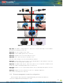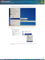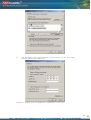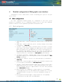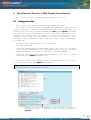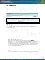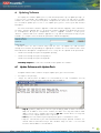
1
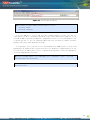
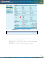
Technical
Description and
User Guide
SAF FreeMile Full Outdoor Unit Technical Des cription and Configuration Guide • Rev. 1.0 • © SAF
Tehnika J SC 2010SAF FREEMI LE
4Gon www.4Gon.co.uk [email protected] Tel: +44 (0)1245 808295 Fax: +44 (0)1245 808299
1
Table of Contents
1
Overview ..................................................................................................................................................................3
SAF FreeMile Full Outdoor Units ...........................................................................................................3
SAF FreeMile Feature Summary ............................................................................................................4
1.1
1.2
1.2.1
1.2.2
1.2.3
1.3
1.4
Main Features........................................................................................................................................... 4
Mechanical Features ............................................................................................................................... 4
Interfaces/Management .......................................................................................................................... 4
Radio Parameters .......................................................................................................................................5
Application Examples .................................................................................................................................5
1.4.1
1.4.2
1.4.3
1.4.4
1.5
1.6
2
2E1 + Ethernet with SAF FreeMile FODU .............................................................................................. 5
Low Power Active Repeater with SAF FreeMile FODU........................................................................ 6
Metro Ethernet and Mesh Networks with SAF FreeMile FODU ......................................................... 6
SAF FreeMile ring topology..................................................................................................................... 7
Technical Specification ..............................................................................................................................8
Cable Requirements ...................................................................................................................................9
Configuration and Management....................................................................................................................10
Resetting the SAF FreeMile ...................................................................................................................10
Web interface ..............................................................................................................................................10
2.1
2.2
2.2.1
2.2.2
2.2.3
2.2.4
2.2.5
2.2.6
2.2.7
2.2.8
2.2.9
2.2.10
10/100Base-T Port ................................................................................................................................. 10
Assembling the SAF FrreeMile RJ45 connector ................................................................................ 10
Ethernet management connection configuration .............................................................................. 11
Power over Ethernet injection .............................................................................................................. 14
Connecting to Web Interface................................................................................................................. 14
Interface Description ............................................................................................................................. 16
Command execution .............................................................................................................................. 17
Tx power selection.................................................................................................................................. 19
Initial configuration ................................................................................................................................ 19
Initial configuration with Web GUI........................................................................................................ 20
3
Main Web GUI sections ....................................................................................................................................21
3.1
Main page .....................................................................................................................................................21
3.2
Spectrum analy sis .....................................................................................................................................23
4
Detailed configuration in Web graphic user interface............................................................................24
4.1
Main configuration ....................................................................................................................................24
4.1.1
Radio configuration ................................................................................................................................ 24
4.1.2
ATPC configuration ................................................................................................................................ 25
ATPC Algorithm ..................................................................................................................................................... 26
4.1.3
Modem configuration ............................................................................................................................. 27
4.1.4
Loopback configuration ......................................................................................................................... 30
Radio frequency loopback .................................................................................................................................... 31
5
Miscellaneous Controls in Web Graphic User Interface .......................................................................32
5.1
Configuration File ......................................................................................................................................32
5.2
Command Line ...........................................................................................................................................34
5.3
File System ..................................................................................................................................................34
5.4
Security Commands .................................................................................................................................35
6
Updating Software .............................................................................................................................................37
6.1
Update Software with Update Pack .....................................................................................................37
6.2
Uploading File via Ethernet Management Port (TFTP) ..................................................................38
6.3
Uploading File via Ethernet Management Port (FTP) ....................................................................39
7
Pinouts ..................................................................................................................................................................41
7.1
Sealed RJ45 sockets ................................................................................................................................41
Available Accessories ................................................................................................................................................42
8
List of Abbreviations..........................................................................................................................................43
9
SAF Tehnika JS C Contacts......................................................................Error!
Error! Bookmark not defined.
The SAF FREEMI LE Series Full Outdoor Unit Technical Des cription and Configuration Guide • Rev. 1.3
© SAF Tehnika A/S 2010
4Gon www.4Gon.co.uk [email protected] Tel: +44 (0)1245 808295 Fax: +44 (0)1245 808299
2
Proprietary notice
The information presented in this guide is the property of SAF Tehnika, JS C. No part of this
document may be reproduced or transmitted without proper permission from SAF Tehnika,
JSC.
The specifications or information contained in this document are subject to change without
notice due to continuing introduction of design improvements. If there is any conflict between
this document and compliance statements, the latter will supersede this document.
SAF Tehnika, JSC has no liability for typing errors in this document or damages of any kind
that result from the use of this document.
To get up to date information about accessories and their availability, please contact sales
representative.
Note: FODU/ODU does not contain serviceable parts. Warranty will not be applicable in the
event FODU/ODU has been hermetically unsealed.
Note: SAF Tehnika, JS C is not responsible for any radio or TV interference caused
by unauthorized modifications to this equipment. Such modifications could void the user's
authority to operate the equipment.
Copyright Notice
Copyright © 2010 SAF Tehnika, JSC. All rights reserved.
1 Overview
This document briefly describes the SAF FreeMile series Full Outdoor Unit (FODU) covering
the built-in management system, configuration functionality, hardware features, etc.
1.1 SAF FreeMile Full Outdoor Units
SAF FreeMile product family is new next generation product line which is targeting growing
demands for data transmission over microwave radio.
As a result the primary traffic interface for SAF FreeMile radio is Fast Ethernet. As SAF
FreeMile is capable of providing bit rate of up to 100M
100M bps , it is a perfect addition to SAF
portfolio. The excellent SAF FreeMile radio and modem performance allows achieving perfect
system capacity by employing 32-decision states modulation schemes by user’s choice. Apart
from the full system capacity of 1 00M
00M bps , it is possible to configure the radio to any of 10
and 30 MHz channels as well as to any of QPSK
QPS K , 16QAM
16QAM,
QAM 32Q
32Q AM modulations
modulations,
ations thus providing
various capacities to suit particular needs.
SAF Tehnika, JS C has employed most modern design solutions and components to create
high performance compact radio with low power consum ption – <15W per radio.
SAF FreeMile is a perfect building block for any modern future proof wireless network,
including mobile service providers, fixed data service operators, enterprise customers,
municipal and governmental networks among others.
3
4Gon www.4Gon.co.uk [email protected] Tel: +44 (0)1245 808295 Fax: +44 (0)1245 808299
1.2 SAF FreeMile Feature Summary
1.2.1 Main Features
•
Full Outdoor solution
•
Capacity: up to 100
100 M b ps
•
Channel Bandwidth:10
10 and 3 0 M Hz
•
Modulations: QPSK, 16Q
16Q AM,
AM , 32QAM
32QAM
•
Interfaces: 10/100 Eth
•
Traffic: Ethernet + 2E1
•
Frequency band: 17GHz and 2 4 GHz
•
Green Radio – <1 5W power consumption
•
ACM and ATPC with Q oS four priority queues
•
802.1Q VLAN support
1.2.2 Mechanical Features
•
Compact unit, 2 30x2
30x230
x230x8
30x85
x85mm,
mm 2.0 kg
Figure 1.1
1.1:
.1 SAF FreeMile Full Outdoor Unit
1.2.3 Interfaces/Management
•
SAF FreeMile unit provides 2 connectors and a RSSI LED
•
User and NM S traffic is carried over Ethernet cable
•
Ethernet traffic supports QoS and 4 priority queues,
queues essential for ACM use
•
User and N MS traffic could be treated as a single data stream or separated by
tagging them with different VLAN tags
•
Web, Telnet and SNMP are available as managem ent interfaces into the unit
4
4Gon www.4Gon.co.uk [email protected] Tel: +44 (0)1245 808295 Fax: +44 (0)1245 808299
2 E1/T1 (RJ45)
RSSI LED
Ethernet + Power (RJ45)
Figur e 1.2
1. 2: SAF FreeMile Full Outdoor Unit
1.3 Radio Parameters
•
SAF FreeMile is a good example of latest achievements in modem and transceiver
development, providing both excellent radio parameters (System Gain), due to use of
QPSK and QAM m odulations
odulation s and efficient despite it consumes small amount of
power Tx/Rx part of the sy stem.
•
RSL Threshold at BER 10 -6 , 30MHz, 32QAM , 100Mbps: - 77 dBm .
•
System Gain with guaranteed max Tx power and Rx sensitivity is 62 dBm
dBm .
•
ACM (Adaptive Coding and Modulation) , hitless ACM opens new possibilities
depending on network designer’s strategy.
•
ATPC
ATPC,
PC Automatic Transmitter Power Control, for increased deployment density
capability.
•
Very high flexi bility allows configuring the sy stem to various channel bandwidths,
modulation schemes and capacity settings.
1.4 Application Examp les
1.4.1 2E1 + Ethernet with SAF FreeMile FODU
•
SAF FreeMile replaces the existing low capacity E1 radio system by preserving E1 connectivity
where needed and adding high capacity Ethernet channel for future use, it is perfect for
overlaying GSM network with 3G/WiMax and LTE (Long Term Evolution) services;
•
Suitable for transition from TDM to Ethernet based networks;
•
SAF FreeMile supports SNMP protocol for NMS.
5
4Gon www.4Gon.co.uk [email protected] Tel: +44 (0)1245 808295 Fax: +44 (0)1245 808299
1.4.2 Low Power Active Repeater with SAF FreeMile FODU
•
Extends network to non line-of-sight locations;
•
Ideal for crossing mountains and interconnecting Ethernet networks;
•
Low power consumption allows using alternative power sources like solar panel or small
wind turbine with battery stand-by support for repeater sites.
1.4.3 Metro Ethernet and Mesh Networks with SAF FreeMile FODU
•
Suitable for any 100Mbps Ethernet network topology – star, ring, mesh network;
•
Full Outdoor solution with Power over Ethernet cable is efficient for All Outdoor Base station
connectivity;
•
Last Mile Access for demanding power user and many other applications;
6
4Gon www.4Gon.co.uk [email protected] Tel: +44 (0)1245 808295 Fax: +44 (0)1245 808299
1.4.4 SAF FreeMile ring topology
•
Utilization of STP protocol allows SAF FreeMile operation in ring topology
Figure 1.7
1. 7 SAF FreeMile implementation in ring topology
7
4Gon www.4Gon.co.uk [email protected] Tel: +44 (0)1245 808295 Fax: +44 (0)1245 808299
1.5 Technical Specificati on
Frequency band and range (GHz)
Duplex (Tx, Rx) offset
Channel bandwidth (MHz)
Modulation
Capacity range
Configuration
Traffic Interfaces
Tx Power tuning range (dBm)
RSL Threshold at BER 10-6, 30 MHz,
32QAM, 100 Mbps (dBm )
Adaptive Coding and Modulation
(ACM)
Antenna flange
Ethernet with power over Ethernet
cable
24 (24.05 – 24.25)
100 MHz, cross-polar
10 / 30
QPSK / 16QAM / 32QAM
From 12 Mbps to 100 Mbps Ethernet
Up to 2 E1/T 1
1+0
100Mbps Fast Ethernet (RJ45) / 2xE1 (RJ45)
-30 … -15
-77
Hitless
C ircular, 10.3mm
1xRJ45 (data traffic, management port, po wer)
Balanced 2xE1/T1
1xRJ45
Management Port
RJ45 (in-band, op tional VLAN tagg ing)
RSSI
TCP/IP
LED on FODU
WEB management
WEB, SNMP, Telnet - local and remote
Monitoring
Via Telnet, WEB GUI, SAF NMS, SNMP Manager
Loopbacks
Yes, E1, modem, RF loopback
QoS
Max frame size
Flow Control
802.1q VLAN support
Spanning Tree
64 level DiffServ (DSC P) or 8 level 802.1p mapped in
4 prioritization queues with VLAN suppor t
1916 bytes
Yes
Up to 15 concurrent traffic VLANs
802.1d-1998 STP
8
4Gon www.4Gon.co.uk [email protected] Tel: +44 (0)1245 808295 Fax: +44 (0)1245 808299
Ref. ETSI EN 300 019-2-4, class 4.1E; non weatherprotected locations
Stationary use
Temperature range
-33o C to +55o C
Dimensions: HxWxD, mm / weight,
kg
230x230x85 / 2
Input DC voltage
48 V DC ±10%
Max. power consumption
<15W
Channel plan 24/17 GHz
Nr
1
2
3
4
5
6
7
8
9
10
10MHz
TX (MHz)
24055/17105
24065/17115
24075/17125
24085/17135
24095/17145
24105/17155
24115/17165
24125/17175
24135/17185
24145/17195
channels
RX (MHz)
24155/17205
24165/17215
24175/17225
24185/17235
24195/17245
24205/17255
24215/17265
24225/17275
24235/17285
24245/17295
TX (MHz)
30MHz channels
RX (MHz)
24065/17115
24165/17215
24095/17145
24195/17245
24125/17175
24225/17275
Capacity Modes
10MHz channel, 32QAM
Eth.(Mbps)
2E1(Mbps)
2T1(Mbps)
30MHz channel, 32QAM
Eth.(Mbps)
2E1(Mbps)
2T1(Mbps)
26
4
-
100
4
-
27
-
3
100
-
3
40*
-
-
100
-
-
30
-
-
* With FEC optimized for increased capacity but higher RSL threshold.
1.6 Cable Requi rements
10/100Base10/100Base- T
Cat. 5e UTP or better cable is required for power supply, management of device and data
traffic.
SAF FreeMile can be used with any SAF Tehnika additionally provided Power over Ethernet
sourcing equipment (provided power >15 W) . Used voltage is 48 V DC ± 10%, though the
nominal voltage is 48 V, over two of the four available pairs on a Cat. 5e cable. It is possible to
use passive injectors, utilizing spare leads. Refer to Ch apter 9 for detailed information about
pinouts.
Length of Cat. 5e cable must not exceed 100 meters.
9
4Gon www.4Gon.co.uk [email protected] Tel: +44 (0)1245 808295 Fax: +44 (0)1245 808299
2 Configuration and Management
There are three ways to adjust and read settings and operation parameters of the SAF
FreeMile equipment:
1.
using Web terminal connected to the 10/100Base-T management port,
2.
using Telnet terminal connected to the 10/100Base-T management port, or
3.
using NMS or SNMP terminal, connected to the 10 /100Base-T management port,
2.1 Resetting the SAF FreeMile
Depending on the method used, the user may reset the whole terminal or the
management controller individually, see table below for details.
Reset action unplugging power source.
Restarts both the multiplexer modu le and the management
module. Resets all management counters.
Resetting with
button
in Web GUI ‘Configuration System
configuration’ window or using
command prompt command “system
system
reset”
reset
Restarts CPU of the management controller. Resets all
management counters.
Resetting with command prompt
command “system
system reset cold”
cold
Restarts modem and CPU of the management controller.
Resets all management counters.
2.2 Web interf ace
This section describes necessary functionalities of Web interface.
2.2.1 10/100Base-T Port
The 10/100Base-T management port is used to connect the SAF FreeMile to a PC or
Ethernet network for Web, SNMP and Telnet management.
(!) The 10/100Base-T port cable length must not exceed 100 meters.
2.2.2 Assembling the SAF FreeMile RJ45 connector
(!) Attention! Be aware that length of RJ45 connectors may vary! This is the reason why
enclosure of weatherproof connector has room for longest possible R J45 connector.
The following instruction shows how to assemble weatherproof connector in order to
achieve the best possible fit of RJ45 connector with socket.
10
4Gon www.4Gon.co.uk [email protected] Tel: +44 (0)1245 808295 Fax: +44 (0)1245 808299
Figure 2.1. Assembling Ethernet weatherproof connector
Fig. 2.1(1). Put rubber sealing inside the connector as shown. Fastening screw should be
placed on the front part of connector.
Fig. 2.1(2). Put connector parts on the cable.
Fig. 2.1(3). Stick the rubber gasket on the connector.
Fig. 2.1(4). Plug RJ45 connector into the Ethernet socket.
Fig. 2.1(5). Fix the connector to the socket with screw.
Note that cable sealing screw is still not fixed at this moment.
Fig. 2.1(6). Push the RJ45 connector into the socket by pushing the cable and at the same time
seal and fix the cable using cable sealing screw.
Fig. 2.1(7). Assembled cable. Fix the cable to the mast as close as possible to FODU. Do not
bend it! The radius of bending should not be less than 10cm.
Fig. 2.1( 8). Example of correct positioning of RJ45 connector during weatherproof connector
assembly.
Fig. 2.1(9). Example of incorrect position of connector – improper alignment.
Note, that it is too deep in the connector.
2.2.3 Ethernet management connection configuration
Before you proceed to initial link setup with Web GUI , you must perform Ethernet
connection configuration by following these steps:
11
4Gon www.4Gon.co.uk [email protected] Tel: +44 (0)1245 808295 Fax: +44 (0)1245 808299
1)
In “MS Windows” operational system go to Start Settings Network
connections (or Start Settings Control panel Network connections)
2)
Find ‘Local Area Connection’, click right mouse button on it and choose
‘Properties’
3)
Click on ‘Internet Protocol (TCP/IP)’ from the list in the dialog box and then click
on ‘Properties’
12
4Gon www.4Gon.co.uk [email protected] Tel: +44 (0)1245 808295 Fax: +44 (0)1245 808299
4)
In the dialog box enter the following values (so that your PC is in the same subnet
as default SAF FreeMile addresses):
Now you are ready to connect to Web GUI or establish Telnet connection.
13
4Gon www.4Gon.co.uk [email protected] Tel: +44 (0)1245 808295 Fax: +44 (0)1245 808299
2.2.4 Power over Ethernet injection
You must have Power over Ethernet sourcing equipment to connect the laptop to the SAF
FreeMile. It is possible to use passive injectors, utilizing spare wire pairs of Ethernet cable.
Refer to Chapter 9 for detailed information on pinouts. Power over Ethernet injector can be
purchased from SAF Tehnika as an optional accessory. Below is an example of Power over
Ethernet injector, as well as its application scheme.
Figure 2.6. Power over Ethernet injector (P/N)
Figure 2.7. Power over Ethernet injector application
The injector has shielded RJ45 sockets. This along with the metal housing helps to reduce
the effects of EMI. A ground lug and terminal are provided directly on the injector housing
providing superior grounding.
Now you are ready to connect to Web GUI or establish Telnet connection.
2.2.5 Connecting to Web Interface
It is recommended to use the following web-browsers (and all later versions):
•
•
•
•
IE v. 6.0
Mozilla Firefox v . 2.0 .0.11
Safari v. 3.0
Opera v. 9 .50
After web browsers selection, open it and enter address of the FODU (Figure
Figure 2.6
2. 6) .
(!) It is important to know the Side parameter of the FODU to which you want to connect;
whether the factory settings are loaded in FODU.
If Low Side -> IP: 192.168.205.10
If High Side -> IP: 192.168.205.11
14
4Gon www.4Gon.co.uk [email protected] Tel: +44 (0)1245 808295 Fax: +44 (0)1245 808299
Figure 2.6
2. 6. SAF FreeMile IP address
(!) The default username and password for Web access are:
–
username: admin
–
password: changeme
If the IP address is correct and you have suitable browser version, you will see
confirmation text. After confirmation you will be redirected to Web interface page. In case of
not valid IP address you will not obtain the configuration interface. In case your browser is not
accepted, you will see the text informing about that. You can push the button “Continue
Anyway” to be redirected to Web interface page.
If everything is correct, you will see the main window of the WEB Interface. If in the field
displaying Local and/or Remote sy stem values there are problems (configured values are not
the same for Local and Remote, or there is a problem with parameter value), the appropriate
cell will be highlighted in red colour.
(!) If you are not obtaining the correct Web page, try to clear browser cookies, cache and
offline data and restart the browser.
(!) All commands executed from Web GUI will be interpreted to CLI commands and will be
executed as in CLI .
15
4Gon www.4Gon.co.uk [email protected] Tel: +44 (0)1245 808295 Fax: +44 (0)1245 808299
Figure 2.7
2. 7. Web Interface - main window of configured link
(!) Note that SAF FreeMile utilizes both polarizations, and radios must be installed with 90 degrees offset
regarding remote side. This, as well as position of cables can be verified in Main status Tx polarization
row.
2.2.6 Interface Description
WEB interface consists of four parts:
1.
2.
3.
4.
Top panel, that allows to log out and gives information about device type, software
version, device name, I P, serial number and uptime;
Menu panel that is used to open links to other pages;
Status summary for local and remote devices: this section is available while browsing
other pages.
The main panel where new pages selected from menu panel are displayed;
16
4Gon www.4Gon.co.uk [email protected] Tel: +44 (0)1245 808295 Fax: +44 (0)1245 808299
Figure 2.8
2. 8. Web Interface description – main window of configured link
Also, special marks are used:
–
–
–
–
Entries highlighted in red indicate that specific parameters do not comply with the
norms of standard operation. For example: value is out of range; local value is not
equal to the remote value and vice versa (only in some places); no value data (N/D).
Entry highlighted in yellow indicates warning.
‘N/D’ in value place corresponds to ‘No Data’.
‘N/A’ in value place corresponds to ‘Not Available’.
2.2.7 Command execution
There is a “Main configuration” page shown in Figure 2.13 . The entire page is divided into
smaller fragments:
1.
2.
3.
4.
5.
6.
The header of page;
Sub-header of single type configuration parameters;
Configuration parameter name;
Configuration parameter current value;
“Apply” button executes configuration changes only on the local side FreeMile FODU.
Enabling rollback feature allows going back to previous configuration in case of
management connectivity loss.
“Apply for local and remote” executes configuration changes on both remote and local
side FreeMile FODUs.
17
4Gon www.4Gon.co.uk [email protected] Tel: +44 (0)1245 808295 Fax: +44 (0)1245 808299
7.
8.
9.
“Save” button, which permanently saves configuration changes for the local side
FreeMile FODU;
“Save in local and remote” button, which permanently saves configuration changes for
the local and remote side FreeMile FODU;
Comments (not on every page) .
“Apply for local and remote ” is available in “Main page” during configuration for local and
remote radio sides simultaneously. Connection between both management CPUs must be
established in order to complete successfully configuration execution for both sides.
“Rollback on” feature is intended to maintain connectivity of the SAF FreeMile link by
cancelling last erroneous configuration changes and reverting to previous successful
configuration used. Rollback will activate only if you lose connection to WEB interface of SAF
FreeMile after configuration changes applied, and reverting process will take approx. 3
minutes.
After parameter value editing, when the focus from this object is removed, this parameter
value edit box may be highlighted in red, meaning that entered value is not valid.
If “Apply ” or “Apply for local and remote” buttons are pressed, and one or several
configuration values edit boxes is/are highlighted in red, the user will see error message with
the explanation text.
Figure 2.9
2. 9. Web Interface - IP configuration page with numbering
18
4Gon www.4Gon.co.uk [email protected] Tel: +44 (0)1245 808295 Fax: +44 (0)1245 808299
2.2.8 Tx power selection
Tx power should not exceed equivalent isotropically radiated power (EIRP) limitation of 20
dBm.
(!) In the table below please see interdependence between antenna used and allowed Tx
output power range (resulting EIRP ≤ 20 dBm) . Particular table shows data for 24 GHz
frequency range.
Antenna size / gain
Allowed Tx power
30cm / 35.0dBi
60cm / 40.3dBi
99cm / 45.4dBi
-25…
25 …-15 dBm
-25…
25 …-2 0 dBm
-25 dBm
Erroneous Tx power setting will pop up an error message.
(!) In the table below please see interdependence between antenna used and allowed Tx
output power range (resulting EIRP ≤ 20 dBm) . Particular table shows data for 17 GHz
frequency range.
Antenna size / gain
Allowed Tx power
30cm / 32.5dBi
60cm / 38.0dBi
99cm / 41.6dBi
-25…
25 …-12 dBm
-25…
25 …-18 dBm
-25…25…-21 dBm
Erroneous Tx power setting will pop up an error message.
2.2.9 Initial configuration
In order to perform initial configuration you will need a laptop with LAN card, 2 Category 5 e Ethernet
cables and a Power over Ethernet injector.
•
Your connected laptop should be in the same subnet with manageable SAF FreeMile, so you can
“see” them; that is why, the laptop Ethernet port settings should be set as follows: (in ‘Microsoft
Windows’ go to Control panel Network Connections Local A rea Connection Properties Internet Proto col (TCP/IP) Properties):
–
–
–
IP address 192.168.205.1;
Net mask 255.255.255.0;
everything else is blank.
•
You must have PoE (Power over Ethernet) injector with the minimum of 20W power supply to
connect the laptop to the SAF FreeMile FODU. Power over Ethernet injector can be purchased
from SAF Tehnika JSC as optional accessory.
•
To know IP address, side value should be read from the label. See Chapter 2.3 for details.
–
–
If Low Side -> IP: 192.168.205.10
If High Side -> IP: 192.168.205.11
19
4Gon www.4Gon.co.uk [email protected] Tel: +44 (0)1245 808295 Fax: +44 (0)1245 808299
•
Connect to SAF FreeMile FODU by entering IP address in the browser address line - by default
192.168.205.10 for the low side and 192.168.205.11 for the high side.
(!) Default username for Web, Telnet and FTP access is admin and password is changeme.
•
It is recommended to use the following or later versions of web-browsers:
–
–
–
–
IE v. 6.0
Mozilla Fi refox v. 2.0.0.11
Sa fa ri v. 3.0
Opera v. 9.50
2.2.10 Initial configuration with Web GUI
Initial configuration in Web GUI should be done individually for each SAF FreeMile FODU.
STEP 1
First step is to choose your antenna size (30 or 60cm) in Main page „Radio configuration”. Press
„Apply” button. Note that “Apply for local and remote” button will not operate until microwave link is
established.
STEP 2
Run „Spectrum analysis” while second unit is not transmitting in order to check availability of
required channel as well as overall interference
STEP 3
Judging upon observed interference, choose free channel in 30MHz or change channel bandwidth to
10MHz and change modem configuration if required.
STEP 4
Activate Tx power by choosing Tx power value in Main page „Radio configuration” and pressing
„Apply” button.
STEP 5
All configuration steps should be repeated for the second SAF Fr eeMile unit.
If everything was configured correctly, you will see a screen similar Figure 2.7. (with no alarm
indications).
20
4Gon www.4Gon.co.uk [email protected] Tel: +44 (0)1245 808295 Fax: +44 (0)1245 808299
3
Main Web GUI sections
3.1
Main pag e
The main window in Web GUI is Main page, which shows all main system parameters, and,
in case of failure or any other problem, it tints a specific parameter in red.
Configuration sections of the page allow you to modify main system parameters and set
up the link. For further details please see Chapter 2.2 .10 “Initial configuration with Web GUI”.
To have better understanding of main page, below you can find explanation of every field.
1.
Shows the system name of particular SAF FreeMile, its IP address, serial
number and uptime since the last restart. If uptime is displayed in red, the
connection to CFIP management port was lost;
2.
Shows the firmware version currently being used;
3.
Logout button allows ending the current Web GUI management session and
logging in as a different user if necessary . After pressing the button, you are
automatically redirected to the login page;
4.
Shows short summary of the main operational parameters of local and
remote sy stem.
•
Rx level (or RSL) at both ends must not differ significantly from the
previously calculated value.
21
4Gon www.4Gon.co.uk [email protected] Tel: +44 (0)1245 808295 Fax: +44 (0)1245 808299
•
Rx quality bar with use of colors (red, orange, yellow, green) indicates
current quality of the signal
•
Modulation indicates which modulation mode is used. The same
modulation must be set at both ends.
5.
The tree of Web GUI sections;
6.
Radio side – shows the radio side of local and remote CFIP;
7.
Tx power – shows current transmitter power in dBm;
8.
Rx level – shows current level of received signal. It must not differ
significantly from the previously calculated value;
9.
Tx frequency – shows the transmitting frequency;
10. Rx frequency – shows the receiving frequency;
11. Bandwidth – shows width of currently utilized bandwidth in MHz;
12. Modulation – shows modulation mode set;
13. Ethernet capacity – shows Ethernet capacity set;
14. E1 channels – shows the number of E1 channels set. The number must be
equal at both ends;
15. Modem status – indicates the acquire status of the modem.
‘ACQUIRE_IN_PROGRESS’ will appear during start-up, when modem acquires
required parameters, but in normal operation mode ‘ACQUIRE_LOCKED’ will
be seen. Any other options designate failure;
16. LDPC decoder stress – shows the load of LDPC (low-density parity-check
code) decoder. The LDPC is monitored for the number of errors being
corrected on the input of LDPC decoder (see Figure 3. 1).
Figure 3.1 LDPC decoder operation
As long as LDPC stress value is under the specified thresholds, the amount of
errors (and BER itself) on the output of LDPC remains at zero level.
17. Current modulation Rx / Tx – shows the modulation modes currently utilized;
18. Current Ethernet capacity Rx / Tx – shows the current Ethernet capacities in
both directions;
19. E1 status – shows if the E1 channel is connected or not and shows status of
LOS and AIS indications. To see the status, click on the text;
20. System temperature – shows the device internal temperature in degrees by
Celsius;
21. Tx polarization – shows transmission polarization and position of connectors
and wires at the local side;
22. Name (serial number) – shows system name and serial number;
23. Version string – shows currently installed firmware version. It must match on
both ends of the link;
24. Loopback – shows if any loopback is currently active;
25. RSSI LED – enables or disables RSSI LED indication;
26. Radio antenna diameter – allows to select antenna diameter you are using;
27. Tx power – allows to choose appropriate Tx power value;
28. Tx channel selection – allows choosing one of three (30MHz channel
bandwidth) or ten (10MHz channel bandwidth) channels. For availability
please check “Spectrum analysis”;
22
4Gon www.4Gon.co.uk [email protected] Tel: +44 (0)1245 808295 Fax: +44 (0)1245 808299
29. Modem configuration – allows choosing appropriate channel bandwidth,
Ethernet capacity and number of E1 channels. By default 30MHz channel
bandwidth with 100Mbps capacity is selected;
30. Pressing „Save” button saves in local unit all changes applied;
31. Pressing „Save in local and remote” button saves in both local and remote
units all changes applied;
32. System returned - in case of error or incorrectly entered parameter value, or
other problems in the whole page – info message will be displayed here.
Otherwise it say s “Ok”;
33. Pressing „Apply” button applies all changes for local unit;
34. Pressing „Apply for local and remote” button applies all changes for both
local and remote units;
3.2
Spectrum analysis
With help of spectrum analysis you can check presence of interference in the available
spectrum and judging upon data obtained, you can make a decision which channel to use.
23
4Gon www.4Gon.co.uk [email protected] Tel: +44 (0)1245 808295 Fax: +44 (0)1245 808299
4
Detailed configuration in Web graphic user interface
Configuration section in Web interface allows customizing your sy stem to suit your
specific needs.
4.1 Main configurati on
The main configuration window provides the configuration of most vital system
parameters, including the ones in configuration wizard as well as some other important
parameters. Below is a short explanation of provided customization fields.
4.1.1 Radio configuration
1.
Radio data status – shows if management CPU was able to read data from
radio;
2.
Radio side – shows if radio side you are currently viewing is low or high
(command line – radio side);
3.
Tx power – allows you to define transmitter power. If the RS L is too high
(much higher than normal -50dBm), you might want to lower transmitter
power. Too high Rx level (>20 dBm) may even result in synchronization loss.
The minimum and maximal values you can choose are dependent on
modulation type and CFIP model. Maximal and minimal Tx power values are
shown in the brackets. (command line - radio txpower [<power dBm>]);
4.
Tx frequency (22014000 .. 22582000 KHz) – allows you to enter preferable
transmitter frequency, hence defining utilized channel (command line - radio
txfreq [<freq KHz>]);
5.
Rx frequency – shows the current receiver utilized frequency (command line radio freq);
6.
Duplex shift – shows the duplex shift between the transmitter frequency and
receiver frequency (command line - radio duplexshift );
7.
Tx mute – allows turning transmitter power off. It may be effective when
diagnosing on interference existence – when transmitter power of one side is
off, you should not experience significant RSL on the other side (command
line - radio txmute [on|off]);
8.
By pressing “Execute configuration” changes made to the corresponding
section apply only for the local side CFIP PhoeniX. If “Rollback on” is selected,
configuration will be reverted in case erroneous configuration changes are
applied.
9.
Pressing “Execute for both” applies changes made to the corresponding
section both for local and remote side CFIP FODUs.
24
4Gon www.4Gon.co.uk [email protected] Tel: +44 (0)1245 808295 Fax: +44 (0)1245 808299
4.1.2 ATPC configuration
To configure ATPC, it is necessary to set Rx (remote) “min” and “max” values and enable
the ATPC feature.
ATPC update period and ATPC delta are recommended to be left unchanged.
It is also possible to change the limit of Tx power correction.
(!) Note, that ATPC is mechanism for reducing Tx power, that’s why to make proper use of ATPC,
transmitter power (Tx power) must be set to the maximum value.
1.
ATPC function – allows enabling or disabling ATPC (Automatic Transmit
Power Control). By default this feature is disabled (command line – atpc
[enable|disable]);
2.
ATPC update period (1..5) – allows defining the period in seconds in which
ATPC parameters are being updated. By default the update period is 1 second
(command line – at pc delay <power change delay time 1..5 sec> );
3.
ATPC delta (1 .. 5 dB) – allows defining ATPC delta - an increment or
decrement in which Tx power will be changed. It is highly unadvisable to
change this parameter (command line – atpc delta <tx power correction step
1..5 dBm>);
4.
Tx power correction – displays the amount of transmitter power in decibels
ATPC has currently corrected (command line – atpc status );
5.
Tx power correction limit (-19..-1 dB) – allows defining the amount of dB
ATPC will be able to correct regarding initial Tx power value (command line –
atpc limit <tx power correction limit -19..-1 dB> );
6.
Remote device status – shows if management CPU was able to read data
from remote management CPU;
7.
Rx (remote) level maximum (-60..-20 dBm) – allows defining the maximum Rx
level. ATPC Tx power correction will be performed only in case of exceeding
this defined maximum Rx level (command line – atpc rxmax <rx level max 60..-20 dBm>);
8.
Rx (remote) level minimum (-90..-50 dBm) – allows defining the minimum Rx
level. ATPC Tx power correction will be performed only in case of exceeding
this defined maximum Rx level (command line – atpc rxmin <rx level min 90..-50 dBm>);
9.
By pressing “Execute configuration” changes made to the corresponding
section apply only for the local side CFIP PhoeniX. If “Rollback on” is selected,
configuration will be reverted in case erroneous configuration changes are
applied.
25
4Gon www.4Gon.co.uk [email protected] Tel: +44 (0)1245 808295 Fax: +44 (0)1245 808299
10. Pressing “Execute for both” applies changes made to the corresponding
section both for local and remote side CFIP FODUs.
ATPC Algorithm
ACM can be implemented together with autom atic transmit power c ontrol (ATPC),
(ATPC)
complimentary features that enhance overall sy stem performance. ATPC reduces the average
transmitted power as well as CCI and adjacent-channel interference (ACI), which is caused by
extraneous power from a signal in an adjacent channel. It also enables a more efficient and
cost-effective network frequency plan and deployment, as well as eliminating some of the
receivers’ “upfade” problems by changing the transmitted power according to the link
momentary conditions. The lower average Tx power also extends the equipment’s mean time
between failures.
ATPC can be used together with ACM to control the transmitted power in any given ACM
profile. Different algorithms can be implemented to achieve maximal spectral efficiency or
minimal transmitted power using both features in combination. One implementation could
target maximal spectral efficacy by trying to reach the highest ACM profile, while the other is
willing to compromise on some of the spectral efficiency enabling CCI and ACI reduction. In
any chosen algorithm, ATPC reduces the average transmitted power, benefiting each ACM
profile and any link condition.
The local CFIP FODU receives information (each second) about Rx level from the far-end
CFIP FODU through the service channel; depending on the received Rx level parameter, the
local CFIP FODU adjusts the transmitter power in accordance with the algorithm shown
below.
Figure 4.1.
4.1. ATPC algorithm
26
4Gon www.4Gon.co.uk [email protected] Tel: +44 (0)1245 808295 Fax: +44 (0)1245 808299
4.1.3
Modem configuration
1.
Modem data status – shows if management CPU was able to read data from
modem;
2.
Bandwidth – allows choosing between 3.5 , 7, 14 and 28 MHz bandwidths
available. The default value is 3 .5 MHz. This option is dependent on what
bandwidth you have purchased. The wider bandwidth you have, the higher will
be the overall link bitrate. The maximum bitrate of 108 M bps is available using
28 MHz bandwidth ( command line – ‘modem
modem set <3500|7000|14000|28000>
<min
modulation>
<max
modulation>
<WeakFEC|StrongFEC>
<channel_mask>);
3.
Modulation – allows choosing between QPS K, 16APS K, 32APS K, 64 QAM and
128QAM modulations. The default value is QPSK. The higher modulation order
is, the higher the overall link bitrate, but worse RSL. The maximum bitrate of
108 Mbps is available using 32APSK modulation in Weak FEC mode or 64QAM
modulation in Strong FEC mode ( command line – m odem s et
<3500|7000|14000|28000>
<min
modulation>
< max
modulation>
<WeakFEC|StrongFEC> <channel_mask>). See below the explanation for
Adaptive Coding and Modulation and F EC options;
4.
E1 channels – allows to enable preferable E1 channels. When the total
capacity is over 100Mbps, number of E1 channels does not influence the total
Ethernet capacity (100Mbps), otherwise Ethernet capacity is <total capacity> <number of E1 channels>*2,048 [Mbps]. By default E1 channels are turned off
(command line – e1 set <Number of E1 channels> );
5.
By pressing “Execute configuration” changes made to the corresponding
section apply only for the local side CFIP PhoeniX. If “Rollback on” is selected,
configuration will be reverted in case erroneous configuration changes are
applied.
6.
Pressing “Execute for both” applies changes made to the corresponding
section both for local and remote side CFIP FODUs.
Adaptive code an d modulation (ACM) technology allows operators to achieve highcapacity data transmission over microwave links and improve the link utilization. This reduces
both operational and capital expenditures for maintaining high-capacity links. ACM can
maintain the highest link spectral efficiency possible at any given time in any link condition.
In traditional voice-dominated wireless backhaul transmission networks, service
availability levels of 99.995% are the norm.
However, newer services such as Internet browsing, video streaming and video
conferencing can operate at more relaxed availability levels. With use of QoS prioritizing ACM
can allocate the required availability based on the priority. As a result, high-priority services
such as voice enjoy 99.995% availability , while low-priority services like video streaming are
allocated lower priorities.
Use of QoS prioritizing defines which services should be transmitted under any link
condition and which services should be adapted whenever the link condition is degraded and
the link payload is decreased.
27
4Gon www.4Gon.co.uk [email protected] Tel: +44 (0)1245 808295 Fax: +44 (0)1245 808299
For example, when bad weather has decreased the channel capacity of a link, ACM
maintains high-priority services – such as E1 channels – with full bandwidth capacity while
adapting the bandwidth capacity of low- and mid-priority services such as Internet browsing
(see Figure 4.2).
Figure 4.2.
4.2. ACM bandwidth capacity adaptation
Traffic can be mapped into different priorities, which define the level of service for each
application. Figure 4.3 illustrates how different services – such as rich voice and video – are
mapped into different classes of availability ( CoA) such as 99 .995% or 99 .985%.
(!) Figure 4.3 . represents intermediate modulations. Full range of modulations available is
128QAM, 64QAM , 32APS K, 16APSK, QPS K if ‘128QAM + ACM’ is selected.
The implementation of multiple priorities increases the available capacity up to 10 times
that of standard links. When conditions are clear, the wireless link operates at maximum
capacity and provides all services with the full data rate. When link conditions are poor –
during harsh rain, for example – predefined high-availability services such as voice are not
affected. However, the capacity of low-priority services is adapted dynamically to the changing
link conditions. This is done by provisioning bandwidth according to the link conditions and
traffic priority.
An ACM profile defines the link parameters (modulation) for a given range of the Radial
MSE. The Radial MSE range of each profile defines the threshold for switching from one ACM
profile to another. Each ACM profile has a different spectral efficiency, derived from its
modulation.
The receiver continuously monitors the link condition based on Radial MSE value.
Once the estimators at the receiver side show that the link performance is not suitable for
the current ACM profile, an ACM switching process will be initiated. I n case of degradation in
the link performance, the new ACM profile will include lower modulation, decreasing the link
bitrate. The ACM switching rate is measured in dB/s and is a key feature of ACM systems.
In general, the higher the switching rate, the better the sy stem’s immunity to rapid Radial
MSE changes. When the switching is being executed, the payload rate is being modified to fit
the aggregated data rate to the new available link data rate.
Alternatively, ACM can also be used to increase the link distance, resulting in added link
spectral efficiency. The same concept is implemented as previously, with the margins that
were kept for 99.995-percent bandwidth availability now used to increase the link distance.
Whenever the link conditions are degraded, the sy stem will switch to an ACM profile with
lower spectral efficiency to enable maintaining the link.
28
4Gon www.4Gon.co.uk [email protected] Tel: +44 (0)1245 808295 Fax: +44 (0)1245 808299
The following real-world example illustrates the benefits of ACM . Consider a CFIP link
operating at 23 GHz with 28 MHz channel spacing and 45.9 dB (120 cm) antenna gain. The link
is operating in a moderate rain region similar to central Europe with a distance of 30
kilometers.
The system operation is set to a minimal payload of four E1 connections plus 34 M bps
Ethernet for 99 .995% availability .
Using the new ACM technology, the system was able to operate most of the time at 108
Mbps, depending on the link conditions.
Most of the time system would support a 366Mbps Ethernet connection instead 69 Mbps
connection. The sy stem automatically monitors the link conditions and changes the capacity
without interrupting the data transmission ( hitless changes), as shown in Figure 4.3 .
Figure 4.3.
4.3. Link availability and classes of services
In comparison similar system using 32QAM and providing similar capacity would provide
only 99,981% of availability. Besides, lack of ACM would not provide higher availability. You
would have to decrease the distance, decrease modulation or increase antenna sizes to
achieve 99 ,995% availability for the given link.
This example demonstrates how the new technology, based on an ACM mechanism, can
play a key role in the development of cost-effective next-generation wireless access networks,
by taking advantage of traffic evolution from synchronous TDM traffic to packet IP-based
traffic.
The Weak FEC option allows increasing overall capacity of the link in terms of
deteriorating RS L sensitiv ity threshold. Note, that using 32APS K with total capacity of
100Mbps, CFIP automatically uses Stron
Stron g FEC mode with better sensitivity, but incrementally
enabling E1 channels, CFIP adapts it's forward error correction, till the maximum 108Mbps
capacity (100Mbps Ethernet + 4E1) is enabled and CFIP operates in Weak FEC mode. For
more details refer to table in Chapter 1.6.
29
4Gon www.4Gon.co.uk [email protected] Tel: +44 (0)1245 808295 Fax: +44 (0)1245 808299
4.1.4 Loopback configuration
Loopback tests are accessible using local or remote management methods.
For safety purposes all loopbacks (local and remote) can be set on a fixed time interval
only. If no time interval is specified, the default value is 60 seconds (1 minute).
Figure 4.2.
4.2. Loopback modes
•
E1 loopback mode loops signal back to local end in bounds of E1 interface. E1
loopback mode must be set on the particular channel you are wishing to test. If no E1
channels are selected, E1 loopback mode is not available;
•
NEAR loopback mode loops signal back to local end after the modem;
•
IF loopback mode loops signal back to local end by linking intermediate frequencies.
1.
Loopback – allows choosing loopback mode and its activity time in seconds
(command line – loopbac k) {status | none | if | modem | e1{1|2|3|4}} [<time>]).
2.
By pressing “Execute configuration” changes made to corresponding section
apply only for the local side of SAF FreeMile. If “Rollback on” is selected,
configuration will be reverted in case erroneous configuration changes are
applied.
3.
Writes to configuration file all changes made in the whole page (command
line – c fg write);
4.
FODU returned - in case of error or incorrectly entered parameter value, or
other problems in the whole page – info message will be displayed here.
Otherwise it say s “Ok”.
Additional radio and modem con figuration commands in Telnet/serial interface
Command
Description
modem status
Shows all the modem parameters.
modem configuration show
Displays current configuration file.
modem configuration <file>
Uses separate configuration file.
modem configuration embedded
Switches back to the embedded configuration last used.
modem configuration embedded
Switches back to the embedded configuration last used.
modem
mo dem factory
Resets modem settings to factory defaults.
modem ipremote [on | off]
Allows enabling manual remote IP specifying. By default
remote IP is being obtained automatically.
radio factory [max]
Resets radio settings to factory defaults. By default Tx power
will be turned off. ‘max’ option will switch Tx power to the
maximum value after restart.
30
4Gon www.4Gon.co.uk [email protected] Tel: +44 (0)1245 808295 Fax: +44 (0)1245 808299
Additional loopbac k comman ds in Telnet/serial interface
Command
Description
Loopback status
Displays status of loopback mode.
Loopback {status | none | if |
modem | e1{1|2|3|4}} [<time>]
Sets the specified loopback mode.
Radio frequency loopback
In order to check performance of SAF FreeMile, radio frequency loopback should be used:
a.
In “ToolsCommand line” enter command “radio txpower -10” in o rder to set
transmit output power to -10 dBm;
b.
In “ToolsCommand line” enter command “loopback rf <time_in_ second> ”,
where” < time_ in_seconds> should be substituted by sufficient time of loopback
operation;
c.
Observe Rx level during radio frequency loopback operation (“Status Main
status” Rx level” or “System summary ”)
d.
Using chart below Tx power shouldn’t be set (for ATPC) above Maximum Tx
power at appropriate Rx level observed:
For example, if radio frequency loopback indicated Rx level = -55dBm, Tx power shouldn’t
be set above 5dBm
31
4Gon www.4Gon.co.uk [email protected] Tel: +44 (0)1245 808295 Fax: +44 (0)1245 808299
5 Miscellaneous Controls in Web Graphic User
User I nterface
These controls are located in the Navigation Panel under the “Tools” item.
5.1 Configuration File
File
This section describes operation with SAF FreeMile configuration script.
The management module has RAM and EEPROM chips onboard. When SAF FreeM ile is
booted up, bootstrap is loaded from the EEPR OM into RAM. The bootstrap contains the
parameters that were previously stored in EEPROM using write and/or cfg write commands.
These parameters are stored in EEPROM in the form of script and when booting up, the script
parameters are loaded into RAM. These parameters can be freely changed in run-time, changing the data in RAM. If the SAF FreeMile is shut down without saving the current
configuration (script) in EEPR OM, the original configuration will be restored from EEPROM on
the next boot-up.
Example of script can be observed on the screenshot below.
The script can be edited:
–
string can be added by simply entering required string (see Nr. 7 on the screenshot below)
or by executing command in CLI or in the appropriate Web GUI section (the script will be
supplemented with the new string or the instant string entry will be updated);
–
string can be deleted by entering appropriate line number (see Nr. 2 on the screenshot
cfg delete < string#>” in CLI.
below) or by using “cfg
The changes can be saved in EEPR OM by pressing “Cfg write” button (see N r. 3 on the
screenshot below) or by entering “cfg
cfg write”
write command in CLI.
(!) Note! The parameters that are not specified in the configuration script will have their
default values when the SAF FreeMile is restarted.
Explanation of customization fields:
1.
Window shows contents of configuration script. Commands contained in this
configuration script are executed at every system start-up ( command line –
cfg show );
32
4Gon www.4Gon.co.uk [email protected] Tel: +44 (0)1245 808295 Fax: +44 (0)1245 808299
2.
Delete entry # – allows deleting a specific line of configuration script. You
must type the number represented in configuration script to proceed with
deleting and press 'Delete' button ( command line – c fg delete <line>);
3.
Save edited configuration file – to confirm the changes made, you must write
configuration script into EEPR OM, otherwise changes will not be saved
(command line – cfg write);
4.
Execute current configuration – executes commands present in configuration
script (command line – cfg run );
5.
Input file name to backup cfg in FODU memory – allows choosing file name
under which current configuration script will be saved in the SAF FreeMile
flash memory ( command line – c fg backu p <file>);
6.
Input file name to restore cfg from FODU memory – allows loading
configuration script from previously saved backup file (command line – c fg
restore <file>). To view the contents of flash memory, go to 'Tools -->
Command line' and type in 'tfs ls';
7.
Enter string, which you want to save in cfg – allows you to enter desirable
command, which will be added to the configuration script as the last line
(command line – cfg add <cmdline>);
8.
Load factory configuration file – Resets the configuration by loading in
EEPROM the script with default settings. This command performs the
following actions (in the following order):
1. clears the current script from EEPROM ,
2. creates and stores in EEPROM the new script with the
following settings:
- net ip addr 192.168.205.10 or 192 .168.205.11 (as marked on
the label)
- net ip remaddr 192.168.205.11 or 192.168.205.10
- net ip mask 255.255.255.0
- net ip gw – 255 .255.255.255 (default gateway - none)
- SNMP trap 255.255.255.255 (none)
3. restarts the management controller.
(command line – cfg factory );
9.
To save cfg file on your computer click here – allows downloading
configuration script and saving it on your hard drive.
Additional commands for script editing in command interface
Command
Description
Cfg load
Loads the configuration script from EEPROM into RAM.
Cfg clear
Clears the script stored in RAM.
Cfg insert <line> <cmdline>
Inserts typed command line with specified line number into
configuration script stored in RAM.
Cfg cmd <file with commands>
Restarts CPU of management controller
configuration script from the specified file.
Cfg grou p
Groups commands in configuration script.
and
loads
33
4Gon www.4Gon.co.uk [email protected] Tel: +44 (0)1245 808295 Fax: +44 (0)1245 808299
5.2 Command Line
In the command line you are able to execute all the commands to manage the SAF
FreeMile which are available through command interface. This dialog box interprets
commands as Telnet commands and sends them to the device. The initial screen shows you
the available commands. To view help on a command, type in “< command> ? ”, where
<command> stands for the specific command.
Additional
Additi onal command pr ompt comm ands
Command
Description
Cls
Clears the screen.
Help <command>
Provides help messages for commands.
5.3 File System
System
The software used by the SAF FreeMile management controller is organized in files, which
are stored on Flash disk.
Firmware and boot confi guration files
The following files are required for the SAF FreeMile to start:
–
‘boot.ini’ file, - device boot configuration file. This file is a text file and contains the name
of the firmware file which must be executed on start- up. The file name can be freely
changed, but its default name is ‘boot.ini’; hereinafter, it is assumed that this file has
default filename. The most important factor concerning this file is that it must be
uploaded with ‘B’ and ‘e’ attribute flags (flags are case sensitive!), only then it will be
treated as executive script.
Attribute flags for ‘boot.ini’ file:
B – query run at boot; e – executive script
For information how to upload files in the Flash disk, please refer to C hapter 7 .
–
Firmware file, - this file is the main firmware executable for the appropriate SAF FreeM ile
model. The file name can be freely changed, but its default name will contain the version
and SAF FreeMile model, e.g., ‘SAF FreeMilel000.elf.ezip’. The most important factor
concerning this file is that it must be uploaded with ‘E’ and ‘c’ attribute flags, otherwise
this file will not be used as the firmware.
Attribute flags for firmware file:
E – executable binary; c - compressed
–
–
–
Notes:
The files are uploaded from PC to Flash disk using TFTP/FTP (via Ethernet management
port) For more information about file upload please refer to C h apter 7; configuration
backup files are created by SAF FreeMile management sy stem.
The flash disk may store other files as well, for example - previous firmware versions,
configuration backup files, - up to 7 .7 Mb (about 8 firmware files) .
The attribute flags for files are case sensitive.
34
4Gon www.4Gon.co.uk [email protected] Tel: +44 (0)1245 808295 Fax: +44 (0)1245 808299
–
–
–
The file names can be changed, but it is very important that the file has the necessary
attribute flags; otherwise, the file will not be used either as firmware, or as ‘boot.ini’ type
file.
There are no file extensions in the file sy stem; either file, when edited, is treated as ASCII
text file.
When uploading the file, if the Flash disk stores the file with the same filename as for the
file being uploaded, it will be overwritten with the new file.
Configuration backu p files
Using ‘ cfg backup <filename> ’ command, the user can create the backup file of the
current SAF FreeMile configuration. The configuration backup file is a text file and, when
created, contains the current configuration script, - the same configuration script that are
stored in EEPR OM. Please refer to C hapter 7 for more information on configuration script.
The configuration backup files are stored on Flash disk, where they can be edited or
downloaded to PC. The backup configuration file can be applied in run-time, by consecutively
entering ‘cfg restore <filename> ’ and ‘ cfg run ’ commands. Note: the configuration restored
from file is not stored in EEPR OM and, therefore, will be lost when SAF FreeMile is restarted.
To save it in EEPROM use ‘write’ command.
The user can create and store several configuration files to quickly revert to other SAF
FreeMile site configurations.
Working with files
The following commands are intended to operate with files stored on the Flash disk on the
management controller.
tfs edit <file>
Edits the specified file. This command is applied for editing
configuration backup files and boot configuration file (boot.ini). For
example,
edit boot.ini,Be
– file ‘boot.ini’ will be opened for editing. ‘Be’ specifies that this file
will be saved with attributes ‘B’ and ‘e’. If boot.ini file is intended to be
modified, it should always be opened specifying ‘B’ and ‘e’ flags as in
the example above, this will ensure that file is saved with these
attributes (flags).
To close the file and save changes press Ctrl+Z, to close the file
without saving changes press Ctrl+Q.
The configuration backup files do not require specific attributes.
tfs ls
Displays the list of files stored on the Flash disk and the number of
bytes, both free and used by these files.
‘tfs dir’ can also be used.
tfs cat <filename>
Displays the contents of the text file.
‘tfs type’ can also be used.
tfs del <filename>
Deletes the specified file from Flash disk.
‘tfs rm’ can also be used.
5.4 Security Commands
C ommands
General tips
Telnet server supports one user only, web server supports up to 32 users simultaneously.
35
4Gon www.4Gon.co.uk [email protected] Tel: +44 (0)1245 808295 Fax: +44 (0)1245 808299
By default the username and password for Web server, FTP server and Telnet terminal is:
–
Username (login): admin
–
Password: changeme
The username and password can be changed in Web GUI “System configuration User
configuration”
‘access set <username> <password> [plaintext]’ command.
Take note of upper case and lower case type: it should be taken into account for the
password!
The passwords may contain spaces; if using space(s), the password should be entered in
quotation marks.
For Telnet, FTP and Web GUI the password can be changed by simply entering the security
command ‘access set <username> <password> [plaintext]’ while logged on and then saving the
configuration in EEPR OM by using ‘ write’ command.
To terminate Telnet session press Ctrl+D.
(!) “Guest” account is unable to change its access password.
(!) Specification of the password should alway s be followed by saving the configuration script
(using “cfg
cfg write”
write command); otherwise, the password request will be ignored after the
restart of SAF FreeMile.
36
4Gon www.4Gon.co.uk [email protected] Tel: +44 (0)1245 808295 Fax: +44 (0)1245 808299
6 Updating Software
Software
To simplify the software update process, SAF Tehnika provides special update package, as
a new version is available. This update pack is available as archive (e.g. zip), which includes
firmware file ( with *.elf.ezip extension), boot configuration file (with *.ini extension) and other
files needed for update process. To receive update pack, please contact your SAF Tehnika
distributor.
The main method for software upgrade is Web GUI software upgrade, which automates
the whole software upgrade process. To perform software upgrade from Web GUI, please go
to “Configuration System configuration” and in “Upgrade software” section press
“Browse…” button and locate software upgrade file (e.g. SAF FreeMilel000.elf.ezip) on your
hard disc (see Chapter 4.2.4 for detailed explanation of Web GUI upgrade).
Besides there are other various ways how the user can update the SAF FreeM ile
management software by uploading the appropriate firmware file to the SAF FreeM ile flash
disk and further editing boot configuration file if necessary. The file upload can be performed:
–
via Ethernet management port using update package,
–
via Ethernet management port using FTP, or
via Ethernet management port using TFTP.
Following chapt ers describe other methods how to update the software.
6.1 Update Softw are with Update Pack
To update SAF FreeMile software using the update pack, proceed as follows:
–
uncompress the package;
–
change the SAF FreeM ile IP address to 192.168 .205.10, or edit ‘send.205.xx’ files by
replacing “192.168.205.10” with actual SAF FreeM ile IP address;
– arp – d ip_addr [if_addr] deletes the host specified by ip_addr. If another host with a
duplicate IP address exists on the network, the ARP cache may have had the MAC
address for the other computer placed in it. arp – d is used to delete an entry that
may be incorrect. By default no host is specified.
– rem ttftp.exe 192.168.205.10 put help.txt prefix ignores command execution
– ttftp.exe 192.168.205.10 put SAF FreeM ilel000.elf.ezip,Ec uploads firmware file
named ‘SAF FreeMilel000.elf.ezip’ with attribute flags ‘E’ and ‘c’ to host SAF
FreeMile with I P address 192.168 .205.10.
37
4Gon www.4Gon.co.uk [email protected] Tel: +44 (0)1245 808295 Fax: +44 (0)1245 808299
–
Start TFTP on both link sides in ‘Configuration IP configuration’:
–
run ‘send.205.xx.cmd’ to perform update, where „xx” represents last number of actual
SAF FreeMile IP address. In case the memory is full, upload will halt and error message
will be displayed. In this case user must first delete some files to free enough memory on
the SAF FreeMile Flash disk. Update process screen is shown below:
–
To activate new firmware, firstly restart the management CPU of the remote link side SAF
FreeMile and then the local side SAF FreeMile (traffic flow won’t be interrupted) in
‘Configuration System configuration’:
6.2 Uploading File vi a Ethernet Manag
Manag ement P ort (TFTP)
Assuming that the SAF FreeM ile IP settings are properly configured, proceed as follows:
1.
Connect the SAF FreeMile to network or directly to PC;
2.
Make sure TFTP is running on SAF FreeMile (by default, the TFTP is switched off); to
run the TFTP on SAF FreeMile, connect to SAF FreeMile with Telnet client and enter
the following command: ‘ start tftp ’;
3.
Run the program that enables to use TFTP service, for example command interpreter
(cmd.exe) if using Windows, see Figure 7. 1;
For example, to upload the firmware file ‘SAF FreeMile000.elf.ezip’ with attribute flags
‘E’ and ‘c’, enter command:
4.
tftp
–i
192. 168.20 5.11
FreeMilel
FreeMilel0 01.elf.ezip,
01.elf.ezip, Ec
put
C:\
C:\ files\
files \ S AF
FreeMilel
FreeMilel0 00.elf.ezip
00.elf.ezip
SAF
where:
38
4Gon www.4Gon.co.uk [email protected] Tel: +44 (0)1245 808295 Fax: +44 (0)1245 808299
‘-i’ – key which specifies that file must be transferred in binary image transfer mode;
‘192.168.205.11’ – SAF FreeMile Ethernet management port IP address (host);
‘C:\files\SAF FreeMilel000.elf.ezip’ – firmware file (source);
‘SAF FreeMilel001.elf.ezip’ –file name in the SAF FreeM ile flash memory (destination);
‘Ec’ – file attribute flags ‘E’ and ‘c’; the attribute flags are separated from file name or
source with comma (only comma and no space) and there are no commas or spaces
between flags;
Figure 7.1.
7.1.
5.
If uploaded file is large (like firmware file), it is recommended to defragment Flash
disk. Use ‘ tfs clean ’ command from Telnet or AS CII terminal to perform
defragmentation.
6.
If the uploaded file is the firmware file which should be used by SAF FreeMile, it is
necessary to edit ‘boot.ini’ file by deleting the entry with the old file name and to write
file name of the new firmware file; the ‘boot.ini’ file must be saved with ‘B’ and ‘e’
flags (file attributes). For more information how to edit files, please refer to the
chapter Working with files in Chapter 6.4 .
(!) To copy file from SAF FreeMile Flash disk to PC hard disk via TFTP, use the following
command:
tftp - i 192.168.205.1 1 get filename destination_filename
where
‘192.168.205.11’ – SAF FreeMile port IP address (host);
‘filename’ – file to be copied from SAF FreeM ile to PC; ‘destination_filename’ – destination
path where the file will be saved on PC hard disk.
6.3 Uploading File vi a Ethernet Manag ement P ort (FT P)
Before uploading file via FTP, make sure the SAF FreeMile FTP server is running. To start
it, go to ‘Configuration IP configuration’ in Web GUI and press ‘Start FTP’:
39
4Gon www.4Gon.co.uk [email protected] Tel: +44 (0)1245 808295 Fax: +44 (0)1245 808299
1.
Open command window.
2.
Start FTP client by entering “ ftp ” command (“ftp>” prompt will appear).
3.
Connect
4.
Enter the command “ty pe binary ” to make sure the binary transfer mode is selected.
5.
Use command “s end <local file> <remote file>, <flags> ” to upload files to SAF
FreeMile Flash disk. For example:
to SAF FreeMile FTP server using command “open <SAF
FreeMile_IP_address>”. Type in username and password when prompted (by default
username is admin and password is changeme).
send c:\boot.ini boot.ini,Be
Use flags ‘E’ and ‘c’ if the file is a firmware file; if the file is a boot configuration file
(boot.ini), the flags must be ‘B’ and ‘e’ ( ‘Be
Be’);
Be the flags for configuration backup files may
not be specified.
Use command “ls ” to list files on SAF FreeMile flash disk.
Use command “delete <filename>” to delete the file from the SAF FreeMile Flash disk.
6.
Proceed with steps 5. and 6. in C hapt er 7.1.
You can also use any preferable FTP client if you wish.
40
4Gon www.4Gon.co.uk [email protected] Tel: +44 (0)1245 808295 Fax: +44 (0)1245 808299
7 Pinouts
Pinouts
7.1 Sealed RJ45 sockets
sockets
One RJ45 socket of FreeMile interface is for Ethernet data transfer and power supply, the
second one is for 2xE1 data transfer and for RSSI.
The pinouts of both sockets are shown in the figure below. The drawing is made according
to position of RJ45 ports on FreeMile interface.
RJ45,
RJ 45, 2xE1
RJ45,
RJ 45, Ethernet
1, 4
TX A
1, 2
RX
2, 5
TX B
3, 6
TX
3, 7
RX A/RSSI -/+
4, 5
DC +
6, 8
RX B/RSSI -/+
7, 8
DC -
41
4Gon www.4Gon.co.uk [email protected] Tel: +44 (0)1245 808295 Fax: +44 (0)1245 808299
Available A ccessories
PoE injector & surge protector
Grounding cable
P/N: I0ATPI04
P/N: Z0AK6001
FODU RJ45 connector 8P shield solid
O-ring - rubber gasket to be fitted between
antenna and FODU
P/N FOACNR02
CLAOR001
Test kit for 24GHz
FODU R J45 LTW cable connector case
C24TST02
P/N FOACNR03
Surge protector for 2xE1
P/N: F0ALA001
42
4Gon www.4Gon.co.uk [email protected] Tel: +44 (0)1245 808295 Fax: +44 (0)1245 808299
8
List of A bbreviations
3G – third generation
AC – Alternating Current
ACI – Adjacent-Channel Interference
ACM – Adaptive Coding and Modulation
AGC – Automatic Gain Control
QAM – Amplitude and Phase Shift Keying
ASCII - American Standard Code for Information Interchange
ATPC – Automatic Transmit Power Control
BER – Bit-Error Ratio
BNC connector - Bayonet Neill-Concelman coaxial connector
CCI – Co-Channel Interference
CLI – Command- Line Interface
CPU – Central Processing Unit
CRC – Cyclic Redundancy Check
DC – Direct Current
DiffServ – Differentiated Services
DSCP - Differentiated Services Code Point
EEPROM - Electrically Erasable Programmable Read-Only Memory
EMI – Electromagnetic Interference
ETS – European Telecommunication Standard
ETSI – European Telecommunications S tandards Institute
FIR – Finite I mpulse Response
FO – Fiber Optics
FODU – Full Outdoor Unit
FTP – File Transfer Protocol
GFP – Generic Framing Procedure
GND - Ground
GSM - Global System for Mobile communications
GUI – Graphical User Interface
IEEE - Institute of Electrical and Electronics Engineers
IF – Intermediate Frequency
ISP – Internet Service Provider
ITUITU- T – International Telecommunication Union – Telecommunication S tandardization Sector
LAN – Local Area Network
LDPC – Low-Density Parity-Check Code
LED – Light-Emitting Diode
LTE – Long-Term Evolution
MAC – Media Access Control
MSE – Mean Square Error
NMS – Network Management System
PC – Personal Computer
PDH – Plesiochronous Digital Hierarchy
43
4Gon www.4Gon.co.uk [email protected] Tel: +44 (0)1245 808295 Fax: +44 (0)1245 808299
PLL – Phase-Locked Loop
PoE - Power over Ethernet
QAM - Quadrature amplitude modulation
QoS – Quality of Service
QPSK - Quadrature Phase-Shift Keying
RAM – Random Access Memory
RSL – Received Signal Level
RSSI – Received Signal Strength I ndicator
Rx – Receive
SNMP - Simple Network Management Protocol
SNR – Signal-to-Noise Ratio
STP – Spanning Tree Protocol
STMSTM - 1 – Synchronous Transport Module - 1
TCP/IP – Internet Protocol Suite (Transmission Control Protocol / Internet Protocol)
TDM – Time-Division Multiplexing
TFTP – Trivial File Transfer Protocol
TM – Tide Mark
TP – Twisted Pair
TS – Threshold Seconds
Tx – Transmission
UAR T – Universal Asynchronous Receiver/Transmitter
USB – Universal Serial Bus
UTP – Unshielded Twisted Pair
VLAN – Virtual Local Area Network
WAN – Wide Area Network
SAF FreeMile and Go FreeMile are trademarks of SAF Tehnika
JSC. All rights reserved. The content is subject to change
without notice.
44
4Gon www.4Gon.co.uk [email protected] Tel: +44 (0)1245 808295 Fax: +44 (0)1245 808299