1
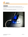
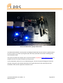
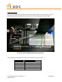
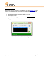
Connect2 Bootloader
User Guide
Connect2 Bootloader User Guide 1.1
©LPRS Ltd 2012
Page 1 of 7
Connect2 Usb Board:
The Microchip PIC processor mounted on the LPRS Connect2-USB board contains a factory
programmed bootloader allowing the device to be more conveniently programmed via the onboard
USB connection.
The processor can also be programmed by connecting a PICkit (or other Microchip compatible)
programmer directly to the ICSP header pins as shown below.
Picture1: Connect2-USB with PICkit Programmer
Connect2 Bootloader User Guide 1.1
©LPRS Ltd 2012
Page 2 of 7
Picture2: Bootloader Jumper Placement
To enable the bootloader, remove power and bridge the PGD and PGC pins with the supplied jumper
(as shown above). On power up the green (Rx) and red (Tx) LEDs flash three times indicating entry
into bootloader mode
Using the microchip C30 compiler linker script and software (supplied on http://www.lprs.co.uk) any
program hex file can now be ‘flashed’ into the processor.
To exit bootloader mode and ‘run’ the flashed program, remove the jumper bridging the PGD and
PGC pins. The green and red LEDs should then once again flash three times indicating exit from
bootloader mode and the application should then run.
Connect2 Bootloader User Guide 1.1
©LPRS Ltd 2012
Page 3 of 7
Connect2 Dev Board:
The processor on the Connect2 DEV board can also be programmed by connecting a PICkit (or other
Microchip compatible) programmer to the header pins and connecting them as shown below
Picture3: Connect2 DEV with PICkit Programmer
The connections between PICkit and PIC micro-controller are as shown below:
PICKIT PIN Header
AUXILARY
PGC
PGD
VSS
VDD
VPP
Connect2 Bootloader User Guide 1.1
©LPRS Ltd 2012
PIC 24FJ128GB106 Pins
NOT CONNECTED
RB1(PIN15)
RB0(PIN16)
Ground (Use Ground socket pins)
+3.3 V (Use 3.3V socket Pins)
MCLR(PIN7)
Page 4 of 7
Picture4: Bootloader Jumper Placement
To enable the bootloader, remove power and interconnect pins RE5 and RE6 using a wire jumper
(violet) (as shown above). On power up the green (Rx) and red (Tx) LED flash three times indicating
entry into bootloader mode
Using the linker script and software (supplied on http://www.lprs.co.uk) any program hex file can
now be ‘flashed’ into the processor.
To exit bootloader mode and ‘run’ the flashed progam, remove the wire connecting pins RE5 and
RE6 pins. The green and red LEDs should then once again flash three times indicating exit from
bootloader mode and the application should then run.
Connect2 Bootloader User Guide 1.1
©LPRS Ltd 2012
Page 5 of 7
The PC software application:
The bootloader application program can be downloaded from LPRS website (www.lprs.co.uk). After
installing, run the application and this will detect Connect2 boards connected via USB (WHEN THE
BOARD IS IN BOOTLOADER MODE AS INSTRUCTED ABOVE).
1. Select the board from the list (The green LED will light up on the PCB)
2. Load the hex file (program)
3. Press the ‘flash’ button to program the micro-controller. The flash button will not be
highlighted or enabled until the board is selected and the hex file is chosen.
4. The program will complete and the board can now be disconnected, or the jumper/link
removed.
Picture5: Screen Shot of PC Bootloader Application
Connect2 Bootloader User Guide 1.1
©LPRS Ltd 2012
Page 6 of 7
Copyright
The information contained in this document is the property of Low Power Radio Solutions Ltd and
copyright is vested in them with all rights reserved. Under copyright law this documentation may not
be copied, photocopied, reproduced, translated or reduced to any electronic medium or machine
readable form in whole or in part without the written consent of Low Power Radio Solutions Ltd.
Disclaimer
Low Power Radio Solutions Ltd has an on-going policy to improve the performance and reliability of
their products; we therefore reserve the right to make changes without notice. The information
contained in this document is believed to be accurate however we do not assume any responsibility
for errors or any liability arising from the application or use of any product or circuit described
herein. This document neither states nor implies warranty of any kind, including fitness for any
particular application.
easyRadio modules are a component part of an end system product and should be treated as such.
Testing to fitness is the sole responsibility of the manufacturer of the device into which easyRadio
products are fitted, as is also the deployment into the field.
Any liability from defect or malfunction is limited to the replacement of product ONLY, and does
not include labour or other incurred corrective expenses.
Using or continuing to use these devices hereby binds the user to these terms.
CONTACT INFORMATION
For further information or technical assistance please contact:
Low Power Radio Solutions Ltd
Two Rivers Ind Est
Station Lane
Witney
Oxon
OX28 4BH
England
Connect2 Bootloader User Guide 1.1
©LPRS Ltd 2012
Tel:
Fax:
Web:
Email:
Technical:
+44 (0)1993 709418
+44 (0)1993 708575
http://www.lprs.co.uk
[email protected]
[email protected]
Page 7 of 7