1
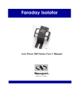
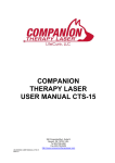
Lyte-MV
User Guide
1. INTRODUCTION
Thank you for purchasing the Lyte-MV laser. This
emits a red / infra-red uniform line. You will have
one of the following two versions:
• CW + Linear intensity / modulation control
version
• CW + TTL modulation control version
If you have any problems or require help when
using the Lyte-MV please call us on +44 (0)1495
212213 or contact your local representative.
2. PRODUCT OPERATION
2A. CW + LINEAR MODULATION / CONTROL VERSION
Connect Binder connector (see diagram A) to back of laser
- CW Mode
To operate laser in CW mode the Red, Black and Blue leads should be connected to the
following:
1.
2.
3.
4.
Red lead: +5 Vdc ( + 10%)
Black lead: 0 Vdc
Yellow lead: Not connected
Blue Lead: V supply if not using as enable switch (enable switch)
- Linear Modulation function
To linearly modulate the laser any modulation signal up to 200 kHz (dependant on diode)
with an amplitude of 0V to +1Vdc can be applied to yellow lead.
1.
2.
3.
4.
Red lead: +5 Vdc ( + 10%)
Black lead: 0 Vdc
Yellow lead: input modulation signal 0 to +1 Vdc
Blue Lead: V supply if not using as enable switch (enable switch)
- Linear intensity control
Alternatively the yellow lead can be used for a linear power control function. In this situation,
the laser power is determined by a voltage applied to the yellow lead, 0V turning the laser off
and +1 Vdc giving maximum power, with linear trend between. (See linear intensity graph)
Red lead: +5 Vdc ( + 10%)
Black lead: 0 Vdc
Yellow lead: input control voltage (0 V to +1 Vdc)
Blue Lead: V supply if not using as enable switch (enable switch)
ser
La
ba
Glo l
1.
2.
3.
4.
Cwmtillery Industrial Estate, Abertillery Gwent. NP13 1LZ
T: +44 (0)1495 212213 F: +44 (0)1495 214004
E: [email protected] W: www.globallasertech.com
- Enable Switch
An on/off switch function is available via the blue wire. Applying 0V will switch the laser off
whilst applying V supply leaves the laser on. A TTL switch can be utilised via this lead. If
not using this function please connect the
lead to the Vsupply.
Setting the power via a resistor
����������������
���
��
��
��
��
�
�
���
���
���
���
���������������������
���
Linear intensity graph
Rx = Po*10k
Pfs-Po
���
The control wire has a 10k Ohm input
impedance connected to an internal 1V
source which is used as the reference
for the factory set power. Measuring the
voltage between the Yellow and Black
wires with a high (>10M Ohm) impedance
voltmeter, will give a reading of 1 V ± 2%.
Connecting a 10k Ohm resistance between
the Yellow and Black wires will result in the
reading falling to 0.5V and the light output
falling to half the factory set power.
Other outputs between 0 and the factory
set power can be achieved with a single
resistor Rx by using the formula:
where Po is the required power output
as Pfs is the factory set power
2B. CW+ TTL CONTROL (TTL CONTROL VERSION)
Connect Binder connector (see diagram A) to back of laser.
- CW MODE
To operate laser in CW mode the Red, Black, yellow and blue leads should be connected to
the following:
1.
2.
3.
4.
Red lead: +5 Vdc (+/- 10%)
Black lead: 0 Vdc
Yellow Lead: +V supply
Blue Lead: V supply if not using as enable switch (enable switch)
- TTL MODE
With this version the yellow wire can be utilised to modulate the laser with a digital TTL input
signal. Two variants are available either digital non-inverting (DNI) TTL or digital inverting
(DI) TTL. The DNI version produces maximum power with a positive TTL signal and zero
power with zero TTL level. Vise-versa for the DI version.
Red lead: + 5 Vdc (+/- 10%)
Black lead: 0 Vdc
Yellow lead: Input TTL signal
Blue Lead: V supply if not using as enable switch (enable switch)
ser
La
ba
Glo l
1.
2.
3.
4.
Cwmtillery Industrial Estate, Abertillery Gwent. NP13 1LZ
T: +44 (0)1495 212213 F: +44 (0)1495 214004
E: [email protected] W: www.globallasertech.com
3. FOCUS ADJUSTMENT
The laser will be tested and shipped to the nominal working distance requested at time of order.
Should you need to adjust the focus please follow the simple instructions below:
1.
2.
3.
4.
5.
Slacken the four 2mm grub screws, which secure the prism lens assembly using the
allen key supplied. (see diagram C)
Remove the prism lens assembly. (see diagram E)
Set up laser at required working distance. Adjust the inner lens assembly by rotating it
with the supplied focus tool (see diagram D) to project the smallest spot at the
required working distance.
Re-fit the line optics and align the ridge of the line lens to the major axis of the laser
beam. Make minor adjustments to achieve an optimum line quality.
Tighten grub screws to lock prism lens assembly in place.
4. OPERATING WITH 11/32 VDC ADAPTOR AND 110/240VAC
ADAPTOR
Please note: these adaptors only operate the laser in CW mode.
• +11 Vdc to +32 Vdc adaptor
1. Remove special power adaptor cable from box
2. Plug DC jack into power supply and screw binder connector into end of laser
3. To the flying leads on the power adaptor connect as follows:
Red: +11 Vdc to +32 Vdc
Black: 0 Vdc
Yellow: Chassis Earth
• 110/240 Vac PS-1 mains adaptor
1. Remove special power adaptor cable from box
2. Plug DC jack into PS-1 power supply and screw binder connector into end of laser
3. Connect IEC mains plug to PS-1 power adaptor
5. SAFETY AND CLASSIFICATION
CLASS 3R LASER PRODUCT
<5mW CW 630-690nm
IEC 60825-1 Amendment 2 / 2001
Class 3R Laser Label
IEC 60825 Warning Labels
ba
Glo l
ser
La
Cwmtillery Industrial Estate, Abertillery Gwent. NP13 1LZ
T: +44 (0)1495 212213 F: +44 (0)1495 214004
E: [email protected] W: www.globallasertech.com
�����������������������
LASER RADIATION
AVOID DIRECT EYE EXPOSURE
Global Laser
�����������������������
Global Laser
�����������������������
�������
IEC 60825-1 Amendment 2 / 2001
Class 2M Laser Label
OEM Laser Label
�������
<1mW CW 690-700nm
�������
CLASS 2 LASER PRODUCT
�����������������������������
LASER RADIATION
DO NOT STARE INTO BEAM
LASER APERTURE
�������
�������
IEC 60825-1 Amendment 2 / 2001
�������
�������
�������
>5mW CW 630-980nm
�����������������������������
A CERTIFIED LASER SYSTEM
LASER APERTURE
�������
�����������������������������
LASER APERTURE
OEM COMPONENT FOR USE IN
Global Laser
These modules are intended for incorporation into customer equipment. They are classified in
accordance with IEC60825-1 Amendment 2/2001, which should be consulted prior to designing
or using any laser product. The following labels are supplied for attachment to the customer’s
equipment, but responsibility for compliance with the standard remains with the user.
6. CLEANING THE OPTICS
If the laser pattern becomes fuzzy or unclear, please check the following:
1.
2.
Check the laser is in focus (see section 3)
Verify the optical lens is clean, if the area has been contaminate please remove
dirt with dry air.
7. MOUNTING
It is recommended to ensure longer life and stability of the laser, the product is mounted in a
suitable heatsink. Global Laser also offer a high quality industrial mount (as pictured diagram F)
that firmly clamps the laser and prevents movement against shock and vibration.
8. PRODUCT WARRANTY AND REPAIR
If your product develops a fault within 12 months from the date of purchase Global Laser
will repair / replace the product. If you wish to return a faulty product contact your local
representative or Global Laser to obtain a RMA (Return Material Authorisation code) and return
to the address below.
9. DIAGRAMS
Lyte MV Laser (B)
Binder Conector (A)
Allen Key hole (C)
Focus Key (D)
Line Optics lens assembly (E)
Heavy Duty Mount (F)