1
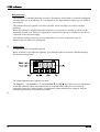
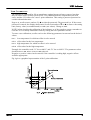
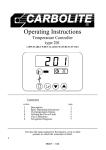
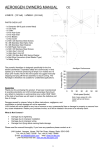
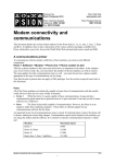
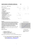
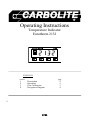
Operating Instructions
Temperature Indicator
Eurotherm 2132
CONTENTS
section
1
2
3
4
page
Description
Operation
User Calibration
Navigation Diagram
1
MC06
2
2
3
4
2132 Indicator
DESCRIPTION
The model 2132 controller/indicator is made by Eurotherm, and is fitted by Carbolite configured
for immediate use as an indicator. It is configured for the input (thermocouple) type for which it
was ordered.
The indicator does not contain a real-time calendar, and is not subject to century-end date
problems.
When the indicator is supplied fitted into a furnace or oven then it is usually on whenever the
Instrument Switch is on. When it is supplied in a separate box, then it is on whenever the box is
connected to the electrical supply.
The indicator will only show the correct temperature if it is also connected to type of
thermocouple for which it is configured.
2
OPERATION
No operator action is normally required.
When switched on, the indicator lights up, goes through a short test routine, and then displays
the measured temperature.
The output light and timer light are not used.
The Page key , the Scroll key 4, and the Down T and Up S keys allow access to parameters
within the controller. Most lists and parameters are hidden and cannot be accessed by the
operator because they contain factory-set parameters which should not be changed. Only the
calibration parameters are normally accessible.
3
2
MC06
2132 Indicator
USER CALIBRATION
The indicator is calibrated for life at manufacture against known reference sources, but there
may be sensor errors or other system errors. User calibration allows compensation for such
errors, and the 2132 allows for a user 2-point calibration. This setting is password protected to
avoid accidental alteration.
Page to iP, scroll to CAL.P, and use Up S to alter the password. The password is 3. If the correct
password is entered, the display shows PASS. Scroll to CAL and use T or S to observe the setting
FACt (factory values, as manufactured) or USEr (user values). Change to USEr.
NOTE: before checking the calibration of the indicator, or of the complete system, remember to
reset the 2132 to factory calibration values by setting the CAL.P parameter to FACt.
To enter a user calibration, scroll to each or the following parameters in turn and set the desired
values.
Pnt.L
low temperature for which an offset is to be entered
OFS.L
offset value for the low temperature
Pnt.H
high temperature for which an offset is to be entered
OFS.H offset value for the high temperature
Example: the controller reads 3°C low at 400°C, and 5°C low at 1000°C. The parameter values
should be Pnt.L=400, OFS.L=3, Pnt.H=1000, OFS.H=5.
Negative or positive values can be entered: if the controller is reading high, negative offsets
would be appropriate.
Fig 4 gives a graphical representation of the 2-point calibration.
MC06
3
4
NAVIGATION DIAGRAM
Home
List
20.0
Input
List
*C
4
iP
Access
List
4
ACCS
4
*C
CAL.P
measured temperature
codE
enter
password
for factory access to
lists and parameters
not available to the
operator
CAL
if user
calibration
Pnt.L
user 2-point
calibration
OFS.L
Pnt.H
OFS.H
For preventive maintenance, repair and calibration of all Furnace
and Oven products, please contact:
Thermal Engineering Services
Telephone: UK: 0845 3308035
Int: +44 1433 623335
Fax:
UK: 0845 3308036
Int: +44 1433 623336
Email:
[email protected]
MC06-1.01
4/10/00
2132ind
Carbolite, Parsons Lane, Hope,
Hope Valley, S33 6RB, England.
Telephone: (01433) 620011
Int: +44 1433 620011
Facsimile: (01433) 621198
Int: +44 1433 621198
E-mail: [email protected]