1
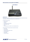
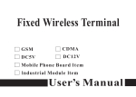
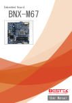
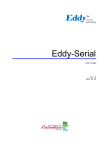
Personality Module v4
User Guide
Product Outline
The Personality Module v4 is a small interface module designed to allow LVDS displays and
touch screens to attach to the Blue Chip Technology RISC Engine series of processor boards
Personality Module
The Personality Module has a number of connections as shown above. Altogether 5 cable
connections are required and a jumper setup is required.
J1: Fit for 4 wire touch screen / no fit for 5 wire touch screen
J2: Fit for 3V3 Panels / no fit for 5V Panels
Connection Overview
Connector Details
P4 - Power
The P4 connector accepts 12V in order to power the backlights on certain panels or the
inverter if one is used
Power is connected as shown on the left
P1 - USB
Pin
1
2
3
4
5
Detail
5V (red)
USBN (white)
USBP (green)
0V (black)
0V
P5 – Touch Screen
Pin
1
2
3
4
5
Detail 5 wire
Down / UR(H)
Right / LR(X)
NC / Sense
Up / UL(Y)
Left / LL(L)
Detail 4 wire
Up / UL(Y)
Right / LR(X)
Down / UR(H)
Left / LL(L)
P6 – LVDS Connection to Panel
Pin
1
3
5
7
9
11
13
15
17
19
21
23
25
27
29
31
33
35
37
39
Definition
12V
GND
VDD (Panel Voltage via J2)
Brightness Control
TX3_P
TCLK_P
TX2_P
TX1_P
TX0_P
GND
Backlight On
Pin
2
4
6
8
10
12
14
16
18
20
22
24
26
28
30
32
34
36
38
40
Definition
12V
GND
VDD (Panel Voltage via J2)
GND
TX3_N
TXLK_N
TX2_N
TX1_N
TX0_N
GND
LCD On
Pins highlighted are only used with a non-inverter based panel display
Where inverter is required, use connector P7 instead
P7 – Inverter
Pin
1
2
3
4
5
6
7
8
Detail
12V
12V
0V
0V
ENABL
BRIGHTNESS
0V
N/C
P2 / P3 – Connection to REx Module
The Personality Module connects to the Risc Engine via a 50 way FFC (Flat Flexi Cable).
Depending on your Panel type use the connections as follows
P2 – for 24 bit panels (MSB on extra LVDS pair TX3)
P3 – for 18 bit panels (but it may suit some 24 bit panels with LSB on extra LVDS pair TX3)
Sample Cables
The Personality Module can be supplied with cables. Sample cable drawings have been
provided below in the event that customers require to create custom cables to suit their own
applications.
Display
Note: Cable is open ended as there is no common connector that is suitable for all possible
display options
Inverter
Note: Cable is open ended as each Inverter option may have different connection options
USB Cable