1
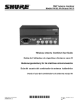
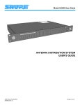
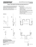
Model PA821
User Guide
A+B OUT
A IN
MAIN OUT
1
2
INPUT SIGNAL
6
5
4
3
7
B IN
POWER
8
T
EXPANSION POR
PA 8 2 1
biner
PSM Antenna Com
470-870 Mhz
50 OHMS
ACTIVE COMBIN
ER
PSM® Antenna Combiner User Guide
Guide de l'utilisateur du répartiteur d'antenne PSM
Bedienungsanleitung für die Antennenweiche PSM
Guía del usuario del combinador de antenas PSM
Guida d'uso del combinatore di antenne PSM
©2008 Shure Incorporated
27A8807 (Rev. 1)
Printed in U.S.A.
ENGLISH
! IMPORTANT SAFETY INSTRUCTIONS !
1.
2.
3.
4.
5.
6.
7.
8.
9.
10.
11.
READ these instructions.
KEEP these instructions.
HEED all warnings.
FOLLOW all instructions.
DO NOT use this apparatus near water.
CLEAN ONLY with dry cloth.
DO NOT block any ventilation openings. Install in accordance with the manufacturer's instructions.
DO NOT install near any heat sources such as radiators, heat registers, stoves,
or other apparatus (including amplifiers) that produce heat.
DO NOT defeat the safety purpose of the polarized or grounding-type plug. A
polarized plug has two blades with one wider than the other. A grounding type
plug has two blades and a third grounding prong. The wider blade or the third
prong are provided for your safety. If the provided plug does not fit into your outlet, consult an electrician for replacement of the obsolete outlet.
PROTECT the power cord from being walked on or pinched, particularly at plugs,
convenience receptacles, and the point where they exit from the apparatus.
ONLY USE attachments/accessories specified by the manufacturer.
12.
USE only with a cart, stand, tripod, bracket, or table
specified by the manufacturer, or sold with the
apparatus. When a cart is used, use caution when
moving the cart/apparatus combination to avoid
injury from tip-over.
13.
UNPLUG this apparatus during lightning storms or when unused for long periods of
time.
REFER all servicing to qualified service personnel. Servicing is required when the
apparatus has been damaged in any way, such as power-supply cord or plug is damaged, liquid has been spilled or objects have fallen into the apparatus, the apparatus
has been exposed to rain or moisture, does not operate normally, or has been
dropped.
DO NOT expose the apparatus to dripping and splashing. DO NOT put objects filled
with liquids, such as vases, on the apparatus.
The MAINS plug or an appliance coupler shall remain readily operable.
The airborne noise of the apparatus does not exceed 70dB (A).
Apparatus with CLASS I construction shall be connected to a MAINS socket outlet
with a protective earthing connection.
To reduce the risk of fire or electric shock, do not expose this apparatus to rain or
moisture.
Do not attempt to modify this product. Doing so could result in personal injury
and/or product failure.
14.
15.
16.
17.
18.
19.
20.
This symbol indicates that there are important operating and
maintenance instructions in the literature accompanying this unit.
This symbol indicates that dangerous voltage constituting a
risk of electric shock is present within this unit.
WARNING: Voltages in this equipment are hazardous to life. No user-serviceable parts inside. Refer all servicing to qualified service personnel. The
safety certifications do not apply when the operating voltage is changed from the factory setting.
DESCRIPTION
The Shure PA821 Antenna Combiners actively combine antenna outputs from up to eight PSM wireless transmitters to a single antenna, improving RF performance and reducing rack clutter.
INSTALLATION
Set the power switch on the front panel to OFF before installing. Connect
the unit to an AC power source using the supplied power cable. Switch the
power ON to use the device. The power light will illuminate. Power the unit
OFF when not in use or before disconnecting the unit from the AC power
source.
PSM Transmitters
8-TO-1 COMBINING:
1.
2.
3.
Using the supplied BNC-BNC cables, connect the ANTENNA
OUTPUT of each transmitter to the ANTENNA INPUTS of the PA821
(Figure 2).
Attach an antenna to the MAIN OUT of PA821. For wideband applications, use PA805 directional antenna (Figure 1).
Connect the PA821 to a power outlet using one of the supplied power
cables. The PA821 contains a universal power supply to operate
anywhere in the world.
NOTE: When the PA821 is powered on, the input signal
indicators (1-8) on the front panel will illuminate if an active
transmitter is connected to the corresponding input (1-8) on the
back panel (Figure 1).
AC
POWER
FIGURE 2
FIGURE 1
2
ENGLISH
SPECIFICATIONS
FOR MORE THAN 8 TRANSMITTERS:
1.
Using the supplied BNC-BNC cables, connect the ANTENNA
OUTPUT of each transmitter to the ANTENNA INPUTS of the
PA821.
2.
Use the 1 ft. jumper BNC-BNC cable to connect the MAIN
OUTPUT of the PA821 to the A IN of the EXPANSION PORT.
Connect another ANTENNA OUTPUT (from a ninth PSM transmitter, second PA821 or other antenna port) to the B IN of the
3.
RF Carrier Frequency Range
470-870 MHz
System Gain
+0/-5 dB
Input AC Line Voltage
100-240 Vac, 50/60 Hz
Maximum Input Line VA
100 VA
Maximum Current Drain
0.42-1.0 Amperes
(Amperes = 100 VA/Input AC Line Voltage)
Maximum RF Input Power
24 dBm (250 mW) per channel
EXPANSION PORT.
4.
Attach an antenna to the A + B OUT of the EXPANSION PORT.
For wideband applications, use the PA805 directional antenna,
Figure 3.
Input Signal Indicator Threshold
+4 dBm (2.5 mW), +2 dBm (1.6 mW) typical
Impedance
50 Ω nominal
Operating Temperature Range
0° F (-18° C) to +135° F (+57° C)
NOTE: Electrical safety approval is based on a maximum
ambient temperature of 35°C.
Overall Dimensions
43.4 mm high x 398.8 mm wide x331.5 mm deep
(1 11/16 in. H x 15 11/16 in. W x 13 1/2 in. D)
Net Weight
4.53 Kg (10 lbs unpackaged, without power and RF cables)
Input/Output Connector Type
BNC-type 8 input, 1 output ACTIVE
2 Inputs, 1 output EXPANSION PORT
FURNISHED ACCESSORIES
(8) 2 ft. Coaxial Cable (RG58C/U) .................................... UA802
1 ft Jumper..................................................................... 95E2035
120 VAC Power Line Cord............................................. 95A8389
230 VAC Power Line Cord............................................. 95A8247
240 VAC Power Line Cord (U.K.) .................................. 95A8713
50Ω BNC
PSM Transmitters
OPTIONAL ACCESSORIES
Wideband Unidirectional Antenna (470-870 MHz) ............ PA805
10 ft. Coaxial Cable (RG-8X/U) ......................................... PA725
25 ft. Coaxial Cable (RG-8X/U) ........................................ UA825
50 ft. Coaxial Cable (RG-8X/U) ........................................ UA850
AC POWER
FIGURE 3
3
ENGLISH
CERTIFICATIONS
PA821: Certified to FCC Part 74 (FCC ID No. DD4PA821). Certified in
Canada by IC to RSS-123 AND RSS-102 (Certification No. IC 616APA821). UL LISTED to UL6500 (2nd Edition) and cUL LISTED to CAN/CSA
E60065-00. Meets the Essential Requirements of the European R&TTE Directive 99/5/EC, eligible to bear CE mark. Meets EMC requirements of EN
301 489 Parts 1 and 9 and is GS-Certified to EN 60065 (6th Edition). Conforms to Australian EMC requirements, eleigible to bear C-Tick mark
(N108).
LICENSING
Changes or modifications not expressly approved by Shure Incorporated could void your authority to operate the equipment. Licensing of Shure
wireless microphone equipment is the user's responsibility, and licensability depends on the user's classification and application, and on the selected
frequency. Shure strongly urges the user to contact the appropriate telecommunications authority concerning proper licensing, and before choosing and ordering frequencies.
THIS RADIO EQUIPMENT IS INTENDED FOR USE IN PROFESSIONAL ENTERTAINMENT AND SIMILAR APPLICATIONS.
NOTE: THIS EQUIPMENT MAY BE CAPABLE OF OPERATING ON
SOME FREQUENCIES NOT AUTHORIZED IN YOUR REGION.
PLEASE CONTACT YOUR NATIONAL AUTHORITY TO OBTAIN
INFORMATION ON AUTHORIZED FREQUENCIES FOR
WIRELESS MICROPHONE PRODUCTS IN YOUR REGION
Licensing: Note that a ministerial license to operate this equipment
may be required in certain areas. Consult your national authority for
possible requirements.
OPERATION OF THIS DEVICE IS SUBJECT TO
THE FOLLOWING TWO CONDITIONS:
1) THIS DEVICE MAY NOT CAUSE INTERFERENCE, AND
2) THIS DEVICE MUST ACCEPT ANY INTERFERENCE,
INCLUDING INTERFERENCE THAT MAY CAUSE
UNDESIRED OPERATION OF THE DEVICE.
www.shure.com
United States:
Shure Incorporated
5800 West Touhy Avenue
Niles, IL 60714-4608 USA
Europe, Middle East, Africa:
Shure Europe GmbH
Wannenäckestr. 28,
74078 Heilbronn, Germany
Phone: 847-600-2000
Fax: 847-600-1212
Email: [email protected]
Phone: 49-7131-72140
Fax: 49-7131-721414
Email: [email protected]
©2008 Shure Incorporated
4
Asia, Pacific:
Shure Asia Limited
Unit 301, 3rd Floor
Citicorp Centre
18, Whitfield Road
Causeway Bay, Hong Kong
Phone: 852-2893-4290
Fax: 852-2893-4055
Email: [email protected]
Canada, Latin America,
Caribbean:
Shure Incorporated
5800 West Touhy Avenue
Niles, IL 60714-4608 USA
Phone: 847-600-2000
Fax: 847-600-6446
Email: [email protected]