1
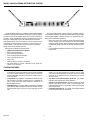
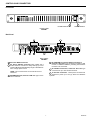
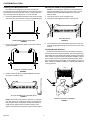
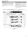
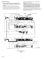
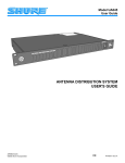
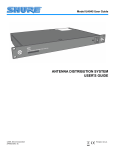
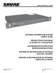
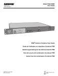
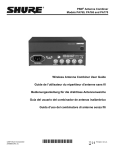
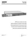
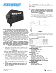
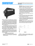
Model UA845 User Guide
UHF
POW ER
A NTEN
NA
UTION
DISTRIB
SYSTE
M
ANTENNA DISTRIBUTION SYSTEM
USER'S GUIDE
©2004, Shure Incorporated
27E8635 (Rev. 5)
Printed in U.S.A.
SAFETY INFORMATION
d
! IMPORTANT SAFETY INSTRUCTIONS !
1.
2.
3.
4.
5.
6.
7.
8.
9.
10.
READ these instructions.
KEEP these instructions.
HEED all warnings.
FOLLOW all instructions.
DO NOT use this apparatus near water.
CLEAN ONLY with dry cloth.
DO NOT block any ventilation openings. Install in accordance with the manufacturer's instructions.
DO NOT install near any heat sources such as radiators, heat registers, stoves,
or other apparatus (including amplifiers) that produce heat.
DO NOT defeat the safety purpose of the polarized or grounding-type plug. A
polarized plug has two blades with one wider than the other. A grounding type
plug has two blades and a third grounding prong. The wider blade or the third
prong are provided for your safety. If the provided plug does not fit into your
outlet, consult an electrician for replacement of the obsolete outlet.
PROTECT the power cord from being walked on or pinched, particularly at plugs,
convenience receptacles, and the point where they exit from the apparatus.
11.
ONLY USE attachments/accessories specified by the manufacturer.
USE only with a cart, stand, tripod, bracket, or table
specified by the manufacturer, or sold with the
apparatus. When a cart is used, use caution when
moving the cart/apparatus combination to avoid
injury from tip-over.
12.
13.
UNPLUG this apparatus during lightning storms or when unused for long periods of
time.
REFER all servicing to qualified service personnel. Servicing is required when the
apparatus has been damaged in any way, such as power-supply cord or plug is damaged, liquid has been spilled or objects have fallen into the apparatus, the apparatus
has been exposed to rain or moisture, does not operate normally, or has been
dropped.
DO NOT expose the apparatus to dripping and splashing. DO NOT put objects filled
with liquids, such as vases, on the apparatus.
14.
15.
This symbol indicates that there are important operating and
maintenance instructions in the literature accompanying this unit.
This symbol indicates that dangerous voltage constituting a
risk of electric shock is present within this unit.
d
MODEL UA845 ANTENNA DISTRIBUTION SYSTEM
The Shure Model UA845 is an amplified, UHF Antenna Distribution System that expands a wireless microphone system by splitting
one pair of antennas to multiple Shure U4 or Shure UC4 wireless
receivers. It also amplifies RF signals to compensate for insertion
loss due to splitting signal power to mulitple output connectors.
Each UA845 allows up to four receivers to use the same antennas.
CASCADE connectors allows connections to a fifth receiver or a
second UA845. There are also power connectors for powering
Shure UHF and UC Wireless systems.
Each system contains the following items:
• UA845 Antenna Distribution System
• Rack-mounting hardware
• Surface-mounting hardware
• Front-mounting antenna hardware
• 18-in. Power OUTPUT Cord
• Power Cord
• Antenna cables for receiver connections
• DC power cables for receiver connections to DC power connectors on UC receivers.
The Shure Model UA845 ensures maximum sensitivity and signal processing capability, providing the widest radio range possible
for the largest number of wireless receivers. To get the most from
this system, follow these guidelines:
• When using long runs of cable for remote-mounted antennas,
use the UA830 In-Line RF Amplifier and the Shure Model
UA825 or UA850 Remote Antenna Extension cables (RG-8/X
or equivalent), which have low loss at UHF operating frequencies
• Locate multiple transmitters more than 3 m [10 ft] from receiving antennas
SYSTEM FEATURES
• Expandability. The UA845 UHF Antenna Distribution System
• Power OUTPUT and OUT Connectors. Up to five (5) U4 re-
•
•
•
is designed for large UHF wireless systems. Each unit allows
up to four wireless receivers to use the same two antennas,
and the CASCADE ports allow connection to a fifth receiver or
a second UA845.
Compatibility. The UA845 is compatible with all Shure wireless microphone receivers operating within a compatible frequency range (see UHF Carrier Frequency Ranges in the
Specifications section).
CASCADE Ports. Two 50 Ω, BNC-type antenna CASCADE
ports allow an additonal UA845 unit or a fifth wireless receiver.
A large wireless system can be run off of a single pair of antennas.
ENGLISH
•
•
6
ceivers can be daisy-chained and powered from a single
source via the Power OUTPUT connectors. Up to four (4) UC4
receivers can be powered from the UA845 using the 12 Vdc
OUT connectors.
Low Noise and Intermodulation Distortion. The UA845
maintains clean signals with minimal distortion.
Insertion Loss Compensation. Whenever a signal is split to
multiple output ports, there is a loss in signal strength. The
UA845 amplifies signals to compensate, ensuring a strong signal to the receivers.
Front-Mounted Antennas. The UA845 comes with hardware
to front-mount the antennas, if desired.
CONTROLS AND CONNECTORS
Front Panel
1
2
POWER INDICATOR
POWER ON/OFF
FRONT PANEL
FIGURE 1
Back Panel
6
1
2
3
6
4
5
3
4
5
BACK PANEL
FIGURE 2
1
AC Power INPUT Connector.
4
2
AC Power OUTPUT Connector. Each UA845 has a
Power OUTPUT connector for daisy-chaining up to five
(5) Shure Model U4 UHF Diversity Single or Dual Receivers to a single power source.
RF CASCADE Connectors (Output connector 5),
Channel A & B. BNC-type connectors for adding a fifth
receiver, or additional UA845's, permitting more wireless
receivers to be connected.
5
RF OUTPUT Connectors, Channel A & B. BNC-type
connectors for up to four wireless receivers.
NOTE: This connector does not work for Shure UC4
Receivers.
3
12 Vdc OUT Connectors. These power connectors are
designed to power up to four (4) Shure UC4 Wireless
systems.
6
ANTENNA IN Ports, Channel A & B. BNC-type connectors for antennas.
7
ENGLISH
SYSTEM INSTALLATION
Installing Front-Mounted Antennas
Mounting the UA845 in an Equipment Rack
The UA845 comes equipped for front-mounted antennas.
Front-mounting improves RF performance of the system by moving
the antennas to the front of the rack. When a unit is located in a
rack, antennas should be either front- or remote-mounted.
1. Insert the bulkhead adapters through the holes in each bracket,
and secure them from each side, using the supplied hardware.
NOTE: If front mounting the antennas, connect them before
mounting the UA845 in the rack. Once in the rack, it is more
difficult to insert the bulkhead adapters and connect the
antenna cables.
1. Insert the unit into a 19-inch equipment rack.
2. Using the screws supplied, secure the unit to the rack.
RACK MOUNTING
FIGURE 6
INSERTING BULKHEAD ADAPTERS
FIGURE 3
3. If the antennas are remote mounted from the back of the rack,
insert the supplied plastic plugs into the holes on the front of the
brackets.
2. Connect the supplied antenna cables to the receiver antenna
inputs and adapters.
Installing Remote Antennas
Remote-mounted antennas have the advantage of being free
from the unit and closer to the transmitters. They can be placed anywhere within the recommended cable length, creating a much wider
radio reception range and further reducing the possibility of signal
dropout. When remote-mounted antennas are desirable, please
ask your Shure dealer for information on the UA830 In-Line RF Amplifier. Cables are available in UA825 (7.5 m [25 ft]) and UA850 (15
m [50 ft]) versions.
UA845
CONNECT ANTENNA CABLES
FIGURE 4
3. Install the antennas onto the bulkhead adapters protruding
through the front panel. See 5.
RECEIVERS
ATTACH ANTENNAS TO THE ADAPTERS
FIGURE 5
REMOTE-MOUNTED ANTENNAS
FIGURE 7
NOTE: For the best results, point the antennas up and away
from each other at 45° angles from vertical. This ensures the
best possible reception and greatly reduces the possibility of
signal dropout. Always perform a walk-through test of the
system in the performing area before using a wireless system.
ENGLISH
8
CONNECTING RECEIVERS
Single UA845 Setup
3. To daisy-chain U4 Receivers together with Power OUTPUT
cables, connect the Power OUTPUT connector of the UA845 to
the Power INPUT connector of one receiver. Connect the
remaining receivers similarly. Connect the POWER INPUT of
the unit to a power supply.
NOTE: No more than five (5) Shure UHF receivers should be
powered through a daisy-chain from a single UA845.
1. Using low-loss, 50 Ω coaxial cables (RG-58 or equivalent), connect the right and left (Channels 1 through 4, A and B) RF
OUTPUT ports on the UA845 to the corresponding left and
right antenna inputs on each receiver. Use the CASCADE ports
to connect a fifth receiver.
2. Using the supplied power cable, connect the UA845 to a power
outlet.
4. To power Shure UC4 receivers, connect the power input ports of
the UC4 receivers to the 12 Vdc OUT of the UA845. Up to four
UC4 Receivers can be powered.
UA845
12 VDC POWER CONNECTOR
ANT B IN
CASCADE B
12 VDC POWER CONNECTOR
CASCADE A
ANT A IN
ANT B OUTS
AC PWR OUTPUT
ANT A OUTS
AC PWR INPUT
TO POWER SUPPLY
ANT B IN
AC PWR OUTPUT
U4 RECEIVER
ANT A IN
AC PWR INPUT
U4 RECEIVER
U4 RECEIVER
UC4 RECEIVER
UC4 RECEIVER
12 VDC PWR INPUT
ANT A IN
ANT B IN
ANT A IN
ANT B IN
SINGLE UA845 SETUP
FIGURE8
9
ENGLISH
Multiple UA845 Setup
remaining receivers similarly. Connect the POWER INPUT of
the unit to an AC power supply.
1. Connect the CASCADE ports (connector 5) for RF OUTPUT
Channels A and B of one UA845 to the ANTENNA INPUT,
channels A and B, of a U4 receiver, a UC4 receiver, or a second UA845.
2. If desired, connect additional units in the same manner.
3. To daisy-chain U4 Receivers together with Power OUTPUT
cables, connect the Power OUTPUT connector of the UA845 to
the Power INPUT connector of one receiver. Connect the
WARNING: When adding additional UA845's to a system,
each UA845 should be connected to a separate power
supply. No more than five (5) receivers can be powered
from a single UA845. Daisy-chaining multiple UA845's
through the Power OUTPUT ports will overload a single
power supply, possibly causing damage to the equipment.
4. To power Shure UC4 receivers, connect the power input ports of
the UC4 receivers to the 12 Vdc OUT of the UA845. Up to four
UC4 Receivers can be powered.
UA845
12 VDC POWER CONNECTOR
ANT B IN
AC PWR OUTPUT
12 VDC POWER CONNECTOR
ANT A IN
CASCADE B
CASCADE A
ANT A OUTS
ANT B OUTS
AC PWR INPUT
TO POWER SUPPLY
TO
RECEIVERS
TO
RECEIVERS
AC PWR OUTPUT
ANT B IN
AC PWR INPUT
U4 RECEIVER
ANT A IN
U4 RECEIVER
12 VDC PWR INPUT
ANT A IN
ANT B IN
UA845
UC4 RECEIVER
TO POWER SUPPLY
TO
RECEIVERS
TO RECEIVERS
U4 RECEIVER
TO UA845
ANT A IN
TO UA845 ANT B IN
MULTIPLE UA845 SETUP
FIGURE 9
ENGLISH
10
SPECIFICATIONS
Certification
UA845: Listed by UL and CUL (U.S. and Canada), IC and FCC;
IC Certified (Canada). Meets applicable European directives
for CE marking eligibility. VDE GS-Certified. Meets Requirements of EMC Standard and 301 489 Parts 1 and 9. Meets the
essential requirements of the European R&TTE Directive
99/5/EC and are eligible to carry the CE marking.
UHF Carrier Frequency Range
UA845-UA .....................................................782–806 MHz
UA845-UB .....................................................692–716 MHz
UA845-MA.....................................................782–810 MHz
UA845-MB.....................................................800–830 MHz
UA845-KK .....................................................838–862 MHz
UA845-MC.....................................................774–782 MHz
UA845 US .....................................................500–900 MHz
UA845 UK .....................................................500–900 MHz
UA845 E ........................................................500–900 MHz
Distributed Output Level (Gain)
Models UA845-UA, UB, MA, MB, KK, MC:
3.5 dB typical, 2.0 dB to 5.0 dB from antenna input
(Output ports 1–4).
0.5 dB typical, –1.0 dB to 2.0 dB from antenna input
(Cascade port)
ModelsUA845 US, UK and E:
3 dB typical, 0 dB to 3.5 dB from antenna input
(Output ports 1–4)
1 dB typical, –1.6 dB to +1.8 dB from antenna input
(Cascade port)
Output Connector Isolation
Greater than 25 dB
Third Order Intercept Point (3 OIP)
Typical 24 dBm
Input/Output AC Line Voltage
100 to 240 Vac, 50/60 Hz, unswitched
DC Output Voltage
12 Vdc, 4 connectors
Impedance
50 Ω
Operating Temperature Range
–7° C (+20° F) to 49° C (+120° F)
Overall Dimensions
44.5 mm high x 482.6 mm wide x 295.3 mm deep
(1 3/4 x 19 x 11 5/8 inches)
Net Weight
3.32 Kg (7 lbs, 5 oz)
Input/Output Antenna Connector Type
BNC-type
AC Power Consumption
15 W per unit typical. When used with 4 UC4's, 55 W max.
Furnished Accessories
2 ft. Coaxial Antenna Cable (RG-58) (12) ................ UA802
Optional Accessories
1/2-Wave Antenna
UA820A .......................................................(774–865 MHz)
UA820B .......................................................(690–746 MHz)
UA820C.......................................................(662–698 MHz)
UA820D.......................................................(554–590 MHz)
UA820E .......................................................(746–784 MHz)
25 ft. Coaxial Cable (RG-8/X)................................... UA825
50 ft. Coaxial Cable (RG-8/X)................................... UA850
30.4 m (100 ft.) Antenna Extension Cable ............ UA8100
In-Line RF Amplifier
UA830A .......................................................(782–810 MHz)
UA830UB ....................................................(692–716 MHz)
UA830C.......................................................(800–830 MHz)
UA830D.......................................................(774–782 MHz)
UA830KK.....................................................(838–862 MHz)
UA830WB....................................................(470–900 MHz)
Active Directional Antenna
UA870A ......................................................(782–810 MHz)
UA870MB ....................................................(800–830 MHz)
UA870MC....................................................(774–782 MHz)
UA870KK.....................................................(838–862 MHz)
UA870UB ....................................................(692–716 MHz)
UA870WB....................................................(470–900 MHz)
Replacement Parts
Hardware Kit........................................................ 90VL1371
Bulkhead Adapters ................................................ 95A8647
120 VAC Power Line Cord .................................... 95A8389
230 VAC Power Line Cord .................................... 95A8247
240 VAC Power Line Cord (U.K.) .......................... 95A8713
120 VAC, 16-in. Power-Through Cord................... 95A8576
230 VAC, 18-in. Power-Through Cord................... 95A8678
12 Vdc Power Cables............................................ 95A8420
THIS RADIO EQUIPMENT IS INTENDED FOR USE IN MUSICAL PROFESSIONAL ENTERTAINMENT AND SIMILAR
APPLICATIONS.
NOTE: THIS RADIO APPARATUS MAY BE CAPABLE OF OPERATING ON SOME FREQUENCIES NOT AUTHORIZED IN
YOUR REGION. PLEASE CONTACT YOUR NATIONAL AUTHORITY TO OBTAIN INFORMATION ON AUTHORIZED
FREQUENCIES FOR WIRELESS MICROPHONE PRODUCTS IN YOUR REGION
11
ENGLISH
LICENSING AND WARRANTY INFORMATION
Warranty. Shure Incorporated (“Shure”) hereby warrants that
these products will be free from defects in material and workmanship for a period of two years from the date of purchase. At its option, Shure will repair or replace the defective product and promptly
return it to you, or refund the purchase price. Retain proof of purchase to validate the purchase date and return it with any warranty
claim. If you believe this product is defective within the warranty period, carefully repack the unit, insure it, and return it postpaid to:
Shure Incorporated
Attention: Service Department
5800 W. Touhy Avenue
Niles, IL 60714-4608 U.S.A.
For service outside the United States, return the product to your
authorized Shure Distribution Center.
All claims of defects or shortage should be directed to the above
address. Please furnish model number, operating frequency, and
date, place and proof of purchase (such as a copy of your sales receipt) to establish warranty. Your letter should include all pertinent
details including applicable model or part numbers and a brief de-
ENGLISH
scription of the problem. Do not mail any units or parts to Shure unless requested to do so by Shure's Service Department. Any
returned items must have prior authorization. Unauthorized returns
are delayed in handling; these delays can be avoided by contacting
Shure in advance and furnishing the necessary information.
Shure reserves the right to make design changes and product
improvements on any previously manufactured products. Shure
also reserves the right to ship new and/or improved products which
are similar to the form, fit and function of the originally ordered products.
Licensing. Changes or modifications not expressly approved by
Shure Incorporated could void your authority to operate the equipment. Licensing of Shure wireless microphone equipment is the user's responsibility, and licensability depends on the user's
classification and application, and on the selected frequency. Shure
strongly urges the user to contact the appropriate telecommunications authority concerning proper licensing, and before choosing
and ordering frequencies other than standard frequencies.
12
43
SHURE Incorporated Web Address: http://www.shure.com
5800 W. Touhy Avenue, Niles, IL 60714-4608, U.S.A.
In U.S.A., Phone: 1-847-600-2000 Fax: 1-847-600-1212
In Europe, Phone: 49-7131-72140 Fax: 49-7131-721414
In Asia, Phone: 1-852-2893-4290 Fax: 1-852-2893-4055
International Fax: 1-847-600-6446