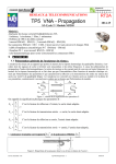
1
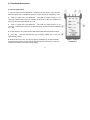
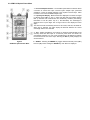
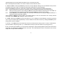
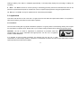
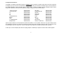
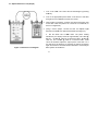
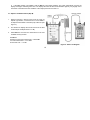
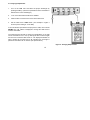
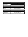
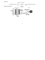
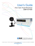
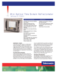
User's Guide
to the
SMLP 5-5
Singlemode / Multimode Light Pack
SMLP-55-1000 Rev. B, 4/6/00
CONTENTS
PAGE
1.0 General.......................................................................................................................................... 2
2.0 Functional Descriptions................................................................................................................. 3
2.1 OLS 5-5 Light Source..................................................................................................... 3
2.2 OPM 5-2C Optical Power Meter...................................................................................... 4
3.0 Applications................................................................................................................................... 6
3.1 Precautions..................................................................................................................... 6
3.2 Required Accessories..................................................................................................... 7
3.3 Typical Applications........................................................................................................ 8
3.4 Optical Reference Level.................................................................................................. 9
3.5 Optical Loss Measurement.............................................................................................. 10
3.6 Editing A Specific Memory Location................................................................................ 11
3.7 Verifying Output Power................................................................................................... 12
4.0 Maintenance.................................................................................................................................. 13
4.1 Battery Replacement....................................................................................................... 13
4.2 Cleaning Optical Ports.....................................................................................................13
4.3 Calibration....................................................................................................................... 13
5.0 Warranty Information..................................................................................................................... 14
5.1 One Year Limited Warranty............................................................................................. 14
5.2 Exclusions....................................................................................................................... 14
5.3 Warranty Registration......................................................................................................14
5.4 Returning Equipment....................................................................................................... 14
6.0 Specifications................................................................................................................................ 15
Appendix……………………………………………………………………………………………………… 16
1
1.0 General
Thank you for purchasing a Noyes Fiber Systems SMLP 5-5 Singlemode / Multimode Light Pack. The SMLP 5-5 provides
the tools necessary to perform power and loss measurements on fiber optic transmission systems. The SMLP 5-5 includes
the OLS 5-5 Light Source, the OPM 5-2C Optical Power Meter, an adapter cap, carry case, PC software, serial cable,
protective rubber boots, trace pads and user’s guides.
The OLS 5-5 is a stable light source with three outputs: 850, 1300, and 1550 nm. The OPM 5-2C is a full featured optical
power meter calibrated at 850, 1300, 1310, and 1550 nm. Both units are lightweight, hand-held, and operate from a single
9V battery.
A fiber optic connector adapter cap of your choice is provided with the OPM 5-2C. The OLS 5-5 is available with ST
connectors. A carry case is provided for convenient storage and transportation.
2
2.0 Functional Descriptions
2.1 OLS 5-5 Light Source
1 - 850 nm Output Port and Adjustment - The 850 nm optical output is a ST connector.
Nominal output power is -20 dBm into 62.5/125 µm fiber and may be adjusted by ±1 dB.
2 - 1300 nm Output Port and Adjustment - The 1300 nm optical output is a ST
connector. Nominal output power is -20 dBm into 62.5/125 µm fiber and -38 dBm into
9/125 µm fiber and may be adjusted by ±1 dB.
3 - 1550 nm Output Port and Adjustment - The 1550 nm optical output is a ST
connector. Nominal output power is -10 dBm into 9/125 µm fiber and may be adjusted
by ±1 dB.
4 - Power Switches - The power switches activate and deactivate the selected outputs.
5 - Low Batt - This LED indicates that the remaining battery life is less than
approximately 1/2 hour.
6- -External AC Power Jack - The OLS 5-5 may be operated by an AC power adapter.
Plugging the AC adapter into this jack will automatically switch the OLS 5-5 from the
internal 9 volt battery to the external power supply.
3
Figure 1 - OLS 5-5
Light Source
2.2 OPM 5-2C Optical Power Meter
1 - Universal Adapter Interface - The threaded optical detector interface allows
connection to various fiber optic connector styles. Adapter caps, purchased
separately, convert the adapter interface to the required connector style. Refer
to section 3.2 for a list of available adapter caps.
2 - Liquid Crystal Display - Measurements are displayed in the lower four digits
in absolute power (dBm or µW) or direct loss (dB) with annunciators defining
REF (a reminder that measurements are referenced), and BAT (low battery).
Resolution is 0.01 dB (.0001 µW) or (.1 dB selectable). The wavelength is
displayed in the top four digits. Out of range HI and LO are displayed in lower
digits.
The OPM 5-2C will automatically detect tone at 270 Hz, 1000 Hz, and 2000 Hz.
When tone is detected, the upper display will alternate between the current
wavelength and the tone detected.
3 - Ref - Holding the Ref key until "HELD" is displayed (approximately three
seconds) stores the dBm input as a reference power level. The OPM 5-2C
automatically switches to a loss mode and displays the dB difference between
the reference level and current input. Selecting the Ref key briefly displays the
stored reference.
Figure 2
OPM 5-2C Optical Power Meter
4 - dB/dBm - Selecting the dB/dBm key toggles between absolute power (dBm)
and loss (dB) modes. Holding the dB/dBm key until "HELD" is displayed
4
(approximately three seconds) switches the OPM 5-2C to a microwatt (µW) mode.
Note: Switching between dB, dBm, and µW will not affect the stored reference levels.
5 - Store and Recall - Selecting the Store key saves the currently displayed reading in the next available memory location
and flashes the location number. The OPM 5-2C stores 500 measurements for each wavelength.
Selecting the Recall key enters the "recall mode" to allow viewing, editing, and printing of stored measurements.
View:
Use the ∧ and ∨ keys to increment or decrement the memory locations and view the stored measurements.
Edit:
Select the memory location to edit. Holding the Store key until "HELD" displays temporarily returns the OPM 5-2C
to a measurement mode. Remeasure the fiber and select the Store key to save the new reading.
Print:
Hold the Recall key until "HELD" displays. The stored data is transferred to a PC (using the supplied software) or a
serial thermal printer (optionally available).
Hold the Store & Recall keys down together until "HELD" displays to clear all stored data at the currently selected
wavelength. Select dB/dBm, Ref, or λ keys to exit the recall mode.
6 - On/Off - Selecting the On/Off key powers the OPM 5-2C on or off. Battery life is automatically conserved by powering
off if no keys are selected within approximately 5 minutes. Disable the automatic shut-down by holding the On/Off key down
during power up until "P" displays.
7 - ∧ and ∨ - In the Recall mode, the ∧ and ∨ keys increment or decrement the memory location. To select .1 dB resolution,
press and hold the ∧ key during power up. To deactivate the serial port, press and hold the ∨ key during power up.
8 - λ - The Greek symbol lambda (λ) is used to denote wavelengths of light. Selecting the λ key defines the measurement
wavelength. The wavelengths available depend on the model - see the specifications section. Annunciators in the LCD will
display the currently selected wavelength.
5
Holding the λ key until “HELD” is displayed (approximately 3 seconds) briefly displays the percentage of battery life
remaining.
9 - Serial - The Serial connector is used for printing or transferring previously stored loss measurements. Data can be
printed to an optional thermal printer or transferred to a PC for complete report generation using the supplied software.
10 - AC Input - The OPM 5-2C may be operated from an external AC power adapter.
3.0 Applications
This section will discuss the use of the OLS 5-5 Light Source and the OPM 5-2C Optical Power Meter. It is important to
follow the precautions given below to ensure proper operation.
3.1 Precautions
Use care when working with any optical transmission equipment. It is good practice to avoid looking directly at the outputs
any optical fibers or optical sources. Always refer to your company safety procedures when working with optical systems.
CAUTION: The use of controls or adjustments or performance of procedures other than
specified herein may result in hazardous laser light exposure. The OLS 5-5 is a registered
CLASS 1 LASER PRODUCT.
It is important to keep all optical connections and surfaces free from dirt, oils, or other
contamination to ensure proper operation. Scratched or contaminated connectors can reduce system performance. Always
replace protective dust caps where available.
6
3.2 Required Accessories
The OPM 5-2C Optical Power Meter requires an "Adapter Cap" to interface to the fiber optic system under test. Note that
an adapter cap of your choice is provided with the SMLP 5-5 kit. Having an assortment of adapter caps on hand would allow
the greatest flexibility if there is limited access to patch cables. A variety of adapter caps are available, please contact
Noyes Fiber Systems to determine the availability of adapter cap types that are not listed below.
1.25mm Universal
2.5mm Universal
FC
SC
ST
E-2000 (Diamond)
Biconic
SMA
LC Simplex/Duplex
Backplane SC
8800-00-0224
8800-00-0214
8800-00-0200
8800-00-0209
8800-00-0202
8800-00-0221
8800-00-0204
8800-00-0203
8800-00-0225
8800-00-0219
Bare fiber
Radiall PFO/VFO
ESCON
DIN 47256
FDDI Kit
FDDI
D4
1000 µm
MU Simplex
MT-RJ, A and B side
8800-00-0206
8800-00-0212
8800-00-0210
8800-00-0211
8800-00-0215
8800-00-0205
8800-00-0201
8800-00-0223
8800-00-0226
8800-00-0231
Optical Jumper Cables are recommended to interface the SMLP 5-5 to the system under test. The jumper cables require
the appropriate connectors on each end to match the system under test's connector style to the OLS 5-5 connector style
and the adapter cap on the OPM 5-2C. Various cable styles and lengths are available from Noyes Fiber Systems.
A fiber optic connector adapter (also called a coupling adapter or bulkhead) is required to mate two fiber cables together.
7
Fiber optic cleaning supplies, such as optical wipes, optics grade alcohol, or cartridge style dry cleaners, should be used to
clean the fiber connector ends. Also, a can of filtered compressed air is useful for blowing out contaminates from adapters.
3.3 Typical Applications
The SMLP 5-5 Singlemode / Multimode Light Pack is used to perform diagnostic and evaluation measurements associated
with fiber optic transmission systems and cable plant. Applications for the SMLP 5-5 will be found within the
telecommunication, cable television, data network, and industrial control industries.
The SMLP 5-5 kit measures absolute power (in dBm or µW ) and loss (dB). Absolute power expressed in dBm is the
amount of optical power received by the detector as compared to 1mW (0dBm=1mW). Measuring dBm is useful for verifying
the output power of an optical transmitter.
Loss is the difference in optical power from a known input (the reference level) and the output power at the opposite end of
the fiber under test. The OPM 5-2C can display dB loss directly after a reference level has been set. Loss measurements
are used to qualify cable plant links and fiber optic jumpers.
Microwatts is also a way to measure absolute power. Some manufacturers specify their transmission equipment in watts
instead of dBm. The OPM 5-2C offers the ability to measure watts for convenience when verifying output power of
transmitters.
For accurate results, always be sure to set the OPM 5-2C to measure the same wavelength as the output of the source or
transmitter.
8
3.4 Optical Reference Level (Step A)
Figure 3 - Reference Level Diagram
1.
Turn on the OPM 5-2C. Select the test wavelength by pressing
the λ key.
2.
Turn on the appropriate power switch on the OLS 5-5 and allow
the light source to stabilize for at least one minute.
3.
Clean all fiber connections. Jumpers must be the same fiber type
as the fiber under test (50/125 µm or 62.5/125 µm multimode, or
9/125 µm singlemode).
4.
Using a launch jumper, connect the OLS 5-5 Optical Light
Source to the OPM 5-2C Optical Power Meter (see Figure 3).
5. Set the OPM 5-2C to dBm mode. The power reading
indicated by the display should be approximately -20.0 dBm @
850 nm ; -20 dBm @ 1300 nm on 62.5/125µm fiber; -38 dBm @
1300 nm; and -10 dBm @ 1550 nm on 9/125µm fiber. If this
cannot be achieved, adjust the output power of the OLS 5-5. If
this still cannot be achieved, try cleaning the optical connections
again and check for excessive bends in the fiber or contact Noyes
Fiber Systems for assistance.
9
6. If the dBm reading is acceptable, hold the Ref key until "HELD" displays. The meter automatically "zeroes" the
display and begins measuring direct loss. The display will read 0.00 dB. The hundredths' digit may vary slightly due to
movement of the fiber and minor variations in the output power from the OLS 5-5.
3.5 Optical Loss Measurement (Step B)
1.
Without removing a launch jumper from the OLS 5-5
Optical Light Source, connect the OLS 5-5 and OPM 52C Optical Power Meter to the fiber (link) under test (see
Figure 4).
2.
The OPM 5-2C displays the end-to-end loss of the fiber
under test (the example shows 1.47 dB).
3.
Select Store to save the loss measurement in the next
available memory location.
EXAMPLE:
Reference (near end) measurement = -20.00 dBm
Far end measurement = -21.47 dBm
End-to-End Loss = 1.47 dB
Figure 4 - Fiber Loss Diagram
10
3.6 Editing a Specific Memory Location
The OPM 5-2C provides 500 memory locations for each of the four wavelengths. A specific memory location can be
changed to correct errors or bad measurements found when viewing the data.
Example: You test and store the measurements for a 48 fiber bundle. After transferring the data to the PC you analyze the
results and find that location #23 appears to have had a problem. You then take the OPM 5-2C back in the field to edit
location #23 and remeasure or fix the fiber.
To Edit:
1.
2.
3.
4.
Select the appropriate wavelength by pressing the λ key.
Press the Recall key and use the ∧ and ∨ keys to choose the memory location number to edit.
Hold the Store key until "HELD" displays. The OPM 5-2C returns to measurement mode.
Remeasure the fiber and select the Store key to save the new reading.
When you return to the PC, transfer download the data again. Now the data has been corrected, eliminating the need to
print a correction addendum to a report.
11
3.7 Verifying Output Power
1.
Turn on the OPM 5-2C and select the proper wavelength by
pressing the λ key. (Check the specifications of the transmitter to
determine the correct wavelength.)
2.
Turn on the transmitter and allow it to stabilize.
3.
Clean the fiber connector and connect to the OPM 5-2C.
4.
Set the OPM 5-2C to dBm mode. (The example in Figure 5
shows a power reading of -16.42 dBm).
If the manufacturer specified the output power in watts, then hold the
dB/dBm key until "HELD" is displayed to change the OPM 5-2C to
measure microwatts.
The measured level should be within the specifications of the light
source manufacturer. If it is not, try cleaning the fiber connector again
and check for excessive fiber bends. A "LO" displayed indicates no
light is present at the meter and a "HI" indicates too much light is
present for the OPM 5-2C to measure (see specifications).
Figure 5 - Verifying Output Power
12
4.0 Maintenance/Calibration
4.1 Battery Replacement
To replace the existing battery in either the OPM 5-2C or the OLS 5-5, remove the battery compartment cover on the back
side of the unit. Place a 9V battery in the unit and then replace the cover.
4.2 Cleaning Optical Ports
OLS 5-5 Light Source - The optical output connectors must be kept free from dirt or other contamination. Most contaminates
can be removed by using a can of filtered compressed air. It is important to keep the dust cap in place when the unit is not
being used.
OPM 5-2C Optical Power Meter - The optical detector must be kept free from dirt or other contamination. The detector
should be periodically cleaned using a low-lint optical grade tissue with optics grade alcohol or by using a can of filtered
compressed air. It is important to keep the dust cap in place when the unit is not being used.
4.3 Calibration
Calibration of the SMLP 5-5 is recommended every 12 months. Please refer to section 5.4 for information on returning
equipment.
13
5.0 Warranty Information
5.1 One Year Limited Warranty
All Noyes Fiber Systems' products are warranted against defective material and workmanship for a period of one year from
the date of shipment to the original customer. Any product found to be defective within the warranty period would be
repaired or replaced by Noyes Fiber Systems. In no case will Noyes Fiber Systems' liabilities exceed the original purchase
price of the product.
5.2 Exclusions
The warranty on your equipment shall not apply to defects resulting from the following:
1. Unauthorized repair or modification.
2. Misuse, negligence or accident.
5.3 Warranty Registration
A warranty registration card is included with the original shipment of equipment. Please take a few moments to fill out the
card and mail or fax it to Noyes Fiber Systems to ensure proper initiation of your warranty term.
5.4 Returning Equipment
To return equipment, please contact Noyes Fiber Systems to obtain additional information and a Return Materials
Authorization number (RMA#). To allow us to serve you more efficiently, please include a brief description describing the
reason(s) for the return of the equipment.
NOYES FIBER SYSTEMS
16 EASTGATE PARK ROAD
BELMONT, NH 03220
TEL: 800-321-5298 OR 603-528-7780
FAX: 603-528-2025
14
6.0 Specifications
MODEL
Optical Power Meter
Calibration Wavelength (nm)
Tone Detection Range (dBm)
Tone Detection Frequency (Hz
Detector Type
Measurement Range
Accuracy ( @ 25°C & -10.0dBm)
Resolution
Power
Adapter Caps
Size (H x W x D)
Light Source
Emitter Type
Emitter Classification
Wavelength
Stability ( @25°C & 20 min. warm-up )
Output Power
Multimode ( 62.5/125µm)
Singlemode ( 9/125µm)
Power
SMLP 5-5
OPM 5-2C
850
+6 to - 30
1300, 1310, 1550
+6 to - 35
270 ± 13.5
1000 ± 50
2000 ± 300
Germanium (Ge)
+6 to -60 dBm
±0.25 dB
0.01 dB (.1 dB selectable)
>30 hrs. typical operation with 9V Alkaline
ST (other styles available)
5.5 x 3.2 x 1.5 in (14.0 x 8.1 x 3.8 cm)
OLS 5-5
LED (850 & 1300 nm), LASER (1550 nm)
Class 1, (FDA CFR 21 and IEC 825)
850, 1300, 1550 nm
±0.1 dB / 1 hr.
-20 dBm @ 850 nm, -20 dBm @ 1300 nm
-38 dBm @ 1300 nm, -10 dBm @ 1550 nm
>8 hrs. typical operation with 9V alkaline, AC adapter optional
15
Optical Connectors
Size (H x W x D)
General Kit Specifications
Dynamic Range of Test Kit
Multimode ( 62.5/125µm)
Singlemode ( 9/125µm)
Weight
Dimensions (H x W x D)
Operating Temperature
Storage Temperature
ST
7.25 x 4.4 x 1.75 in (18.4 x 10.2 x 4.4 cm)
40 dB @ 850 & 1300 nm
22 dB @ 1300 nm, 50 dB @ 1550 nm
3.3 lbs.(1.5 kg)
12 x 12.5 x 4.75 in (30.1 x 31.7 x 12.0 cm)
0° to 50° C
-30° to 60° C
16
Power Port
Reg, 2.5 mm,Tip pos
9VDC @ 200mA (USA)
9VDC @ 500mA (Europe)
RS-232 Pin Designations
PC CABLE
DB 9 Female
3.5mm
17
Thank You for Choosing
Noyes Fiber Systems
16 Eastgate Road • Belmont, NH 03220
Tel: 800-321-5298 • 603-528-7780 • Fax: 603-528-2025
E-Mail: [email protected] • Website: www.noyes-fiber.com
18