1
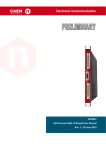
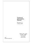
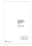
CAEN
Tools for Discovery
Electronic Instrumentation
2091
4
User Manual
Rev. 4 - 14 April 2011
Es
A1523 A1524 A1526 AG523 AG524 AG526
HV Boards User Manual
Rev. 8 - 9 October 2013
Purpose of this Manual
This document is the A1523 A1524 A1526 AG523 AG524 AG526 HV Boards User Manual; it contains information about
the installation, the configuration and the use of the boards
Change Document Record
Date
3 July 2103
18 July 2103
10 September 2013
9 October 2013
Revision
5
6
7
8
Changes
Added Mod. A1523, A1524, AG523, AG524
Functional description updated
Added Mod. AG526
Updated External connections
Symbols, abbreviated terms and notation
T.B.D.
Reference Documents
CAEN S.p.A.
Via Vetraia, 11 55049 Viareggio (LU) - ITALY
Tel. +39.0584.388.398 Fax +39.0584.388.959
[email protected]
www.caen.it
© CAEN SpA – 2011
Disclaimer
No part of this manual may be reproduced in any form or by any means, electronic, mechanical, recording, or
otherwise, without the prior written permission of CAEN SpA.
CAEN will repair or replace any product within the guarantee period if the Guarantor declares that the product is
defective due to workmanship or materials and has not been caused by mishandling, negligence on behalf of the User,
accident or any abnormal conditions or operations.
CAEN declines all responsibility for damages or injuries caused by an improper use of the Modules due to negligence on
behalf of the User. It is strongly recommended to read thoroughly the CAEN User's Manual before any kind of
operation. CAEN reserves the right to change partially or entirely the contents of this Manual at any time and without
giving any notice.
Disposal of the Product The product must never be dumped in the Municipal Waste. Please check your local regulations
for disposal of electronics products.
Made In Italy : We stress the fact that all the boards are made in Italy because in this globalized world, where getting
the lowest possible price for products sometimes translates into poor pay and working conditions for the people who
make them, at least you know that who made your board was reasonably paid and worked in a safe environment. (this
obviously applies only to the boards marked "made in italy", we cannot attest to the manufacturing process of "third
party" boards).
CAEN
Electronic Instrumentation
Index
1.
2.
Introduction ....................................................................................................................... 4
Functional description .............................................................................................................................................. 4
Channel Characteristic Table .................................................................................................................................... 5
Front Panel................................................................................................................................................................ 6
Technical Specifications ............................................................................................................................................ 7
Packaging ...............................................................................................................................................................................7
External connections ..............................................................................................................................................................7
Displays ..................................................................................................................................................................................7
Other components .................................................................................................................................................................7
Safety information and installation requirements ............................................................... 8
General safety information ....................................................................................................................................... 8
Injury Precautions ..................................................................................................................................................................8
3.
Safety Terms and Symbols on the Product ............................................................................................................... 8
Installation ................................................................................................................................................................ 9
Operating modes .............................................................................................................. 10
Output control and monitoring .............................................................................................................................. 10
Output Enable ......................................................................................................................................................... 11
A1526 Current range setting .................................................................................................................................. 11
Grounding specifications ........................................................................................................................................ 13
List of Figures
Fig. 1 – A1526 front panel .......................................................................................................................................................................6
Fig. 2 – A1526 side view ........................................................................................................................................................................11
Fig. 3 – A1526 Current range dip-switch top view .................................................................................................................................12
Fig. 4 – A1526 grounding scheme ..........................................................................................................................................................13
List of Tables
Table 1 – Channel characteristics ............................................................................................................................................................5
3
A1523 A1524 A1526 AG523 AG524 AG526 HV Boards User Manual
CAEN
Electronic Instrumentation
1. Introduction
Functional description
The Model A1523, A1524, A1526 double width board house 6 H.V. channels with either positive or negative
polarity; it is compatible with the CAEN Universal Multichannel Power Supply System (SYx527). The channels share a
common floating ground. Moreover the A1526 offer 100 µA / 1 mA dual current Full Scale Range (dip switch
selectable). The “ground return” version of the boards are also available (AG523, AG524, AG526); the channels
return is wired to the crate Earth reference. Mod. AG526D is a special two channel version of the AG526.
The output ranges are as follows:
Model
A1523/AG523
A1524/AG524
A1526/AG526
V Full Scale
12 kV
12 kV
15 kV
I Full Scale
1 mA
0.1 mA
1 / 0.1 mA
Vset/Vmon resolution
1000 mV
1000 mV
1000 mV
Iset/Imon resolution
100 nA
10 nA
100 / 10 nA
In all models voltage can be programmed and monitored with 1 V resolution.
If the output voltage differs from the programmed value by more than 3% of voltage full scale range, the channel is
signalled to be either in OVERVOLTAGE or UNDERVOLTAGE condition. Moreover, for each channel, a voltage
protection limit SVMAX can be fixed via software with 1 V resolution and the output voltage can not be
programmed beyond this value.
The HV RAMP-UP and RAMP-DOWN rates may be selected independently for each channel in the range 1÷ 500 V/s
in 1 V/s steps.
The output current is monitored with 10 nA (A1524, AG524, A1526/AG526 low range) or 100 nA (A1523, AG523,
A1526/AG526 high range) resolution; if a channel tries to draw a current larger than its programmed limit it is
signalled to be in OVERCURRENT condition; the SY x527 system detects this state as a fault and reacts according to
1
the setting of the TRIP parameter , namely:
TRIP=infinite ( = 1000 s)
When the set output current value is reached the channel behaves like a constant current generator.
TRIP=finite (< 1000 s)
The output current keeps the set value only for programmed time interval and then is switched off.
The TRIP time (i.e. the maximum time an OVERCURRENT condition is allowed to last) can be programmed in 0.1 s
steps.
The maximum output voltage (VMAX Hardware) can be fixed, through a potentiometer located on the front panel,
at the same common value for all the board channels and this value can be read out via software.
The board hosts also a temperature sensor located on the PCB near the HV channels: the temperature values
measured by this sensor are used to signal Over Temperature condition on the SY x527.
The board is provided with an "HV EN" input that disables the channels when it is not connected to ground. The
front panel hosts an Earth connector for flexible grounding scheme (see § 4.4).
HV Output is provided through CPE HV coaxial connectors; A652 cable adapters (CPE HV into LEMO HV
ERA3S415CTL) are available.
1
Refer to the SYx527 User’s Manuals for details about the TRIP Handling.
A1523 A1524 A1526 AG523 AG524 AG526 HV Boards User Manual
4
Electronic Instrumentation
CAEN
Channel Characteristic Table
Table 1 – Channel characteristics
Model:
A1523/AG523
Polarity:
A1524/AG524
Positive / Negative depending on purchased version
Output Voltage:
0 ÷ 12 kV
Max. Output Current:
1mA
0 ÷ 15 kV
100 µA
high range 1mA; low range 100µA
Voltage Set/Monitor Resolution:
1V
Current Set/Monitor Resolution:
100 nA
VMAX hardware:
10 nA
10 nA /100 nA depending on current range
0÷12 kV common for all channels
VMAX hardware accuracy:
0÷15 kV common for all channels
± 2% of FSR
VMAX software:
0÷12 kV settable for each channel
0÷15 kV settable for each channel
VMAX software resolution:
1V
Ramp Up / Down:
Voltage Ripple:
A1526/AG526
1÷500 Volt/sec, 1 Volt/sec step
2
Voltage Monitor
Accuracy: 3
< 300 mV pp
vs.
Output
Voltage
± 0.3% ± 2 V
4
± 0.3% ± 1 V
Voltage Set vs. Voltage Monitor Accuracy:
Current Monitor vs. Output Current Accuracy:
Current Set vs. Current Monitor Accuracy:
6
5
± 2% ± 1 µA
± 2% ± 0.1 µA
± 2% ± 1 µA (1 mA range)
± 2% ± 0.1 µA (100 µA range)
± 2% ± 0.1 µA
± 2% ± 0.01 µA
± 2% ± 0.1 µA (1 mA range)
± 2% ± 0.01 µA (100 µA range)
2
From DC to 15 MHz at full load
From 10% to 90% of Full Scale Range
4
From 10% to 90% of Full Scale Range
5
From 10% to 90% of Full Scale Range
6
From 10% to 90% of Full Scale Range
3
5
A1523 A1524 A1526 AG523 AG524 AG526 HV Boards User Manual
CAEN
Electronic Instrumentation
Front Panel
Fig. 1 – A1526 front panel
A1523 A1524 A1526 AG523 AG524 AG526 HV Boards User Manual
6
CAEN
Electronic Instrumentation
Technical Specifications
Packaging
The module is housed in a 2 units wide, 6U-high mechanics.
External connections
The location of all components of the front panel is shown in Fig. 1.1, p. 8. The function and electro-mechanical
specifications of the external connectors are listed in the following subsections.
CH 0…5 HV CONNECTORS:
Mechanical specifications:
CPE 23.100.151-046 type male connector to be mated with CPE
23.100.052-045 type.
Electrical specifications;
HV coaxial connector
operating voltage (mated): 15 kV dc
operating intensity: 1 mA
HV EN CONNECTOR
Mechanical specifications:
00-type LEMO connector.
Electrical specifications: board ENABLE input, if it is connected to ground,
the channels are enabled.
EARTH CONNECTOR:
Mechanical specifications:
R921921000 RADIALL 2mm Socket
Electrical specifications;
R contact: < 2 mΩ
Displays
CH ON 0..5 LEDs:
Function: they light up as the relevant channel is on.
Type: red LEDs for positive polarity version; yellow LEDs for negative
polarity version
Other components
VMAX trimmer:
7
Function: it allows to adjust the hardware maximum voltage VMAX
common to all the channels. Its value can be read out via software.
A1523 A1524 A1526 AG523 AG524 AG526 HV Boards User Manual
Electronic Instrumentation
CAEN
2. Safety information and installation requirements
General safety information
This section contains the fundamental safety rules for the installation and operation of the board. Read thoroughly
this section before starting any procedure of installation or operation of the product.
Injury Precautions
Review the following precautions to avoid injury and prevent damage to this product or any products connected to
it. To avoid potential hazards, use the product only as specified. Only qualified personnel should perform service
procedures.
Avoid Electric Overload.
To avoid electric shock or fire hazard, do not apply a voltage to a load that is outside the range specified for that
load.
Avoid Electric Shock.
To avoid injury or loss of life, do not connect or disconnect cables while they are connected to a voltage source.
Do Not Operate Without Covers.
To avoid electric shock or fire hazard, do not operate this product with covers or panels removed.
Do Not Operate in Wet/Damp Conditions.
To avoid electric shock, do not operate this product in wet or damp conditions.
Do Not Operate in an Explosive Atmosphere.
To avoid injury or fire hazard, do not operate this product in an explosive atmosphere.
Do Not Operate With Suspected Failures.
If you suspect there is damage to this product, have it inspected by qualified service personnel.
Safety Terms and Symbols on the Product
These terms may appear on the product:
•
DANGER indicates an injury hazard immediately accessible as you read the marking.
•
WARNING indicates an injury hazard not immediately accessible as you read the marking.
•
CAUTION indicates a hazard to property including the product.
The following symbols may appear on the product:
DANGER
High Voltage
A1523 A1524 A1526 AG523 AG524 AG526 HV Boards User Manual
ATTENTION
Refer to Manual
8
CAEN
Electronic Instrumentation
Installation
The modules are double-width boards. At power ON the SYx527 system processor will scan all the slots in the crate
to find out where the module is plugged and what kind of module it is.
9
A1523 A1524 A1526 AG523 AG524 AG526 HV Boards User Manual
Electronic Instrumentation
CAEN
3. Operating modes
The modules can be controlled, either locally or remotely, through the SYx527 software interface. For details on
SYx527 system operation, please refer to the User's Manual of this product. The following sections contain a
description of commands available for the board control and status monitoring.
ATTENTION
THE MODULES REQUIRE
SY1527-2527 FIRMWARE VERSION 1.09.04 OR LATER
Output control and monitoring
For each output channel, it is possible, through the SYx527 system, to perform the following operations:
•
•
•
•
•
•
•
•
•
•
•
•
Assign to channel a symbolic name
Set output voltage (VSET)
Set max. output current (ISET)
Set output voltage software limit (SVMAX)
Set voltage ramp-up speed (RAMP-UP)
Set voltage ramp-down speed (RAMP-DOWN)
Set TRIP parameter
Enable/disable POWER ON option
Switch channel ON/OFF
Monitor output voltage (VMON)
Monitor output current (IMON)
Monitor channel status
If the POWER ON option is enabled, the channel, at POWER ON, is restored in the same condition it was before the
POWER OFF or RESET; if this option is disabled, at POWER ON or after a RESET, the channel is kept OFF
independently from its previous condition.
The following messages may be returned by the SYx527 when monitoring the channel status:
•
•
•
•
•
•
•
•
•
OFF
RUP
RDWN
OVC
OVV
UNV
EXTTRIP
INTTRIP
EXT_DIS
(channel turned OFF)
(channel ramping up)
(channel ramping down)
(channel in OVERCURRENT condition)
(channel in OVERVOLTAGE condition)
(channel in UNDERVOLTAGE condition)
(channel OFF due to external TRIP line signal)
(channel OFF due to internal OVERCURRENT condition)
(channel disabled by board INTERLOCK protection)
Moreover it is possible to monitor board temperature and to check board status; the following messages may be
returned by the SYx527 when monitoring the board status:
•
•
UNDER_TEMP (board temperature < 5°C )
OVER_TEMP
(board temperature > 65°C)
A1523 A1524 A1526 AG523 AG524 AG526 HV Boards User Manual
10
CAEN
Electronic Instrumentation
Output Enable
The board is provided with an "HV EN" input that enables the channels when it is connected to ground.
When the channels are disabled the voltage outputs drop to zero at the maximum rate available; when the output
disable cause is removed, i.e. the "HV EN" connector is connected to ground, the channels remain OFF until the
User turns them ON via software.
A1526 Current range setting
The Mod. A 1526 current Full Scale Range, can be selected between 100 µA and 1 mA by dip-switch (please refer to
the figure below for the dip-switch location on the board).
TABC
Dip Switch
(side view)
Out 0
Channel 0
Out 1
Channel1
Out 2
Channel 2
Out 3
Channel 3
Out 4
Channel 4
Out 5
Channel 5
43 2 1
Controller
earth
HV EN
Fig. 2 – A1526 side view
In order to select the desired current Full Scale Range (common to all channels), the dip-switch must be set, by
looking at the board's top side, as illustrated in figure below.
Current range selection must be performed before inserting the board into the crate.
Default factory setting is 1 mA Full Scale Range.
11
A1523 A1524 A1526 AG523 AG524 AG526 HV Boards User Manual
CAEN
Electronic Instrumentation
Top view
(FSR = 1 mA)
1 2 3 4
on
PCB
Dip-switch 2 = ON
Dip-switch 1, 3, 4 = OFF
(FSR = 100 µ A)
1 2 3 4
on
PCB
Dip-switch 1, 2, 3, 4 = OFF
FRONT
PANEL
Fig. 3 – A1526 Current range dip-switch top view
A1523 A1524 A1526 AG523 AG524 AG526 HV Boards User Manual
12
CAEN
Electronic Instrumentation
Grounding specifications
HV Board
Channels
Crate
Earth
Floating
ground
Fig. 4 – A1526 grounding scheme
The Mod. A1523, A1524 and A1526 channels share a common floating ground, which does not coincide with the
crate ground, which is available as Earth connector on the front panel of the board. This feature allows on-detector
grounding, thus avoiding loops which may increase noise level. Floating ground and Earth may be coupled in several
ways (see scheme above), according to the environment requirements.
13
A1523 A1524 A1526 AG523 AG524 AG526 HV Boards User Manual
CAEN
Electronic Instrumentation
Tools for Discovery
CAEN SpA is acknowledged as the only company in the world providing a complete range of High/Low Voltage Power
Supply systems and Front-End/Data Acquisition modules which meet IEEE Standards for Nuclear and Particle Physics.
Extensive Research and Development capabilities have allowed CAEN SpA to play an important, long term role in this field.
Our activities have always been at the forefront of technology, thanks to years of intensive collaborations with the most
important Research Centres of the world. Our products appeal to a wide range of customers including engineers, scientists
and technical professionals who all trust them to help achieve their goals faster and more effectively.
CAEN S.p.A.
Via Vetraia, 11
55049 Viareggio
Italy
Tel. +39.0584.388.398
Fax +39.0584.388.959
[email protected]
www.caen.it
CAEN
Tools for Discovery
CAEN GmbH
Klingenstraße 108
CAEN Technologies, Inc.
D-42651 Solingen - Germany
Phone +49 (0)212 254 4077
Fax +49 (0)212 25 44079
Mobile +49 (0)151 16 548 484
[email protected]
Staten Island, NY 10305
USA
Tel. +1.718.981.0401
Fax +1.718.556.9185
[email protected]
www.caentechnologies.com
www.caen-de.com
1140 Bay Street - Suite 2 C
Electronic Instrumentation
A1523 A1524 A1526 AG523 AG524 AG526 HV Boards User Manual rev. 8 - 9 October 2013
00102-00-A1526-MUTX
A1523 A1524 A1526
AG523 AG524 AG526 HV Boards User Manual
Copyright © CAEN SpA. All rights reserved. Information in this publication supersedes all earlier versions. Specifications subject to change without notice.
14