1
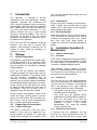
lined piping component in the system, unless
some other constraint from another item in the
system requires a lower test pressure to be
used.
In undertaking a pressure test, care should be
taken to ensure that pressure is applied from the
upstream side of all non-return valves, and is
released from the downstream side of all such
valves to ensure (a) a pressure test of the
complete system and (b) all of the test pressure
has been removed from the system at the end of
the test.
3.1.4
Gaskets
Gaskets are not normally required where PTFE
lined items are being connected to similar
products. Where components are connecting to
dissimilar materials such as glass, ceramic or
exotic metal then the use of a PTFE envelope
gasket or similar device is recommended.
3.1.5
Vent Holes
The majority of lined products contain vent holes
(typically 3mm diameter). These holes fulfil two
critical purposes:
(1) In some circumstances depending on
temperature, pressure and the chemistry of the
contained media, a small amount of material
may permeate through the liner. As it reaches
the outside of the PTFE, it can form a trapped
gas and if this permeant is not allowed to
escape through the vent holes, it can lead to the
collapse of the liner in the lined component.
(2) To provide an early indication of liner failure.
Rather than a liner failure occur catastrophically
the vent holes can indicate a problem possibly
before it becomes serious.
Where vent holes exist, the user is responsible
for setting up a system to regularly check them.
If any product is leaking from the vent holes, the
item in question should be removed from service
without delay, since catastrophic failure is likely
to occur if no action is taken. It is therefore
important not to block the vent holes with paint
or any other substance. This requirement
applies equally to systems where vent
extensions/plugs are utilised.
3.1.6
Bolting Materials
Bolting materials should be of good quality,
clean and well lubricated. The use of washers is
recommended to ensure correct even torque.
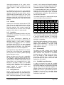
Bolts should be tightened by use of a torque
Issue Date: 19/5/10
User Guide - Rev 7 May 10.doc
wrench in strict sequence of diagonally opposite
pairs. This, and all subsequent torquing, of bolts
should be undertaken at ambient temperature.
It is recommended that all bolts are retorqued a
minimum of 24 hours after commissioning or
following the initial full process cycle. The torque
of all bolted joints should then be rechecked at
least annually thereafter.
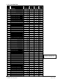
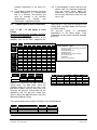
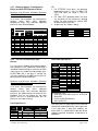
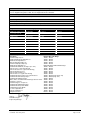
The following table gives recommended torque
levels for flange to flange connections.
Nominal Bore
Imp
Metric
1"
1.1/2"
2"
3"
4"
6"
8"
10"
12"
25
40
50
80
100
150
200
250
300
Torque
Ft Ibs
Nm
14
20
35
54
40
80
100
94
107
19
27
47
73
54
108
136
127
145
Qty
4
4
4
4
8
8
8
12
12
Bolts/Studs
Size
Size
(Metric)
(UNC)
M12
1/2"
M12
1/2"
M16
5/8"
M16
5/8"
M16
5/8"
M20
3/4"
M20
3/4"
M24
7/8"
M24
7/8"
The torque values given above are a guide; they
may be exceeded by a value of 50% to effect a
seal. If once this torque level has been reached
a seal has not been achieved, it is likely that
some other source of failure, such as scratched
flare faces, is operating.
Note: When bolting together dissimilar materials,
always tighten to the lowest recommended
torque of the components in the joint. Using
higher torques may result in damage to the
softer material in the joint.
3.1.7
Disassembly
The bolts on lined systems must not be
loosened while the system temperature is above
60°C otherwise flare distortion or irrevocable
damage may occur. Always secure end covers
on to the flanges of lined components which
have been removed from a system, this will
prevent damage, the ingress of dirt and allow
trouble free re-assembly.
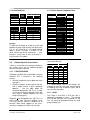
3.1.8
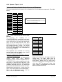
Stud/Bolt Length Calculator
In order to calculate the length of stud/bolt
required for any joint, it is necessary to calculate
the half joint length for the two flanges that make
up the joint, and then add them together. In
addition, allowance must be made for any wafer
pattern item, such as an instrument tee, that is
included in the joint. The information below
provides the data necessary to allow these
calculations to be made.
Page 3 of 16