1
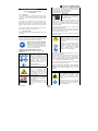
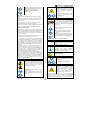
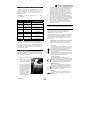
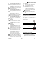
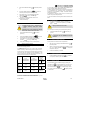
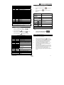
SUPRA 900 / 1000 / 1000Mt° CITY Z OPERATING INSTRUCTIONS INTRODUCTION This guide has been prepared for the operator of Carrier Transicold refrigeration units. It contains basic instructions for the daily operation of the refrigeration unit as well as safety information, troubleshooting tips, and other information that will help you to deliver the load in the best possible condition. Please take the time to read the information contained in this booklet and refer to it whenever you have a question about the operation of your Carrier Transicold unit. This manual refers to the standard model. Some options may not appear in it, and in such cases you are requested to consult our Technical Services. Your refrigeration unit has been engineered to provide long, trouble-free performance when it is properly operated and maintained. The checks outlined in this guide will help to minimize on the road problems. In addition, a comprehensive maintenance program will help to insure that the unit continues to operate reliably. Such a maintenance program will also help to control operating costs, increase the unit's working life, and improve performance. When having your unit serviced, be sure to specify genuine Carrier Transicold replacement parts for the highest quality and best reliability. At Carrier Transicold, we are continually working to improve the products that we build for our customers. As a result, specifications may change without notice. CONTENTS CE CONFORMITY DECLARATION ............................................................................................................................................................ 4 1. DESCRIPTION & IDENTIFICATION ................................................................................................................................................. 5 1.1. Nameplate .............................................................................................................................................................................. 5 1.2. Noise level sticker................................................................................................................................................................... 5 2. SAFETY ............................................................................................................................................................................................ 5 2.1. Warning stickers maintenance................................................................................................................................................ 7 3. PRODUCT LOADING ....................................................................................................................................................................... 7 4. RECOMMENDED TRANSPORT TEMPERATURES ........................................................................................................................ 8 5. PRETRIP INSPECTION .................................................................................................................................................................... 8 6. DISPLAY BOAD ................................................................................................................................................................................ 8 6.1. Cab control ............................................................................................................................................................................. 8 6.2. Auxiliary control panel ............................................................................................................................................................ 9 7. OPERATION ..................................................................................................................................................................................... 9 7.1. To start the unit – ROAD operation ........................................................................................................................................ 9 7.2. To start the unit – STANDBY operation ................................................................................................................................ 10 7.2.1. Standby operation guideline ...................................................................................................................................... 10 7.3. To stop the unit ..................................................................................................................................................................... 10 7.4. To change set point temperature .......................................................................................................................................... 10 7.5. To initiate manual defrost ..................................................................................................................................................... 10 7.6. To display unit data .............................................................................................................................................................. 10 7.7. To change a function ............................................................................................................................................................ 11 7.8. To operate with auxiliary control panel ................................................................................................................................. 11 7.8.1. To change the set point ............................................................................................................................................. 11 7.8.2. To set pre-set set point .............................................................................................................................................. 11 7.8.3. To remove pre-set set point ....................................................................................................................................... 12 7.8.4. To lock and unlock the control panel.......................................................................................................................... 12 8. PROBLEMS .................................................................................................................................................................................... 12 8.1. Fuses location ...................................................................................................................................................................... 12 8.2. Fault alarm display and safety features ................................................................................................................................ 12 9. MAINTENANCE .............................................................................................................................................................................. 12 9.1. Maintenance schedule .......................................................................................................................................................... 13 9.2. Recommended hydraulic oil ................................................................................................................................................. 13 10. A.T.P. EUROPE REGULATION EXTRACT .................................................................................................................................... 13 11. 24H ASSISTANCE .......................................................................................................................................................................... 14 62-61778-01 3 CE CONFORMITY DECLARATION CONFORMITY DECLARATION TO THE E.E.C. DIRECTIVES We, Manufacturer declare that the machine designated "SUPRA CITY Z" complies with the provisions of the directives: - 2006 / 95 / EEC, Low voltage, - 2004 / 108 / EEC, EMC, - 2006 / 42 / EEC, Machinery, - 1997 / 23 / EEC, PED, - 2000 / 14 / EEC, Noise, - 1972 / 245 / EEC, - 1970 / 156 / EEC - 2009 / 19 / EEC e & E Mark - "SUPRA CITY Z" classified in article I according to 1997 / 23 / EEC directive. Carrier Transicold Industries S.C.S. 810 route de Paris 76520 Franqueville Saint Pierre (France) CARRIER TRANSICOLD INDUSTRIES SCS. au capital de 7 145 000 Euros RCS ROUEN B 410 041 677 - SIRET 410 041 677 00023 - CODE APE 292 F - Identifiant T.V.A. FR 46410041677 62-61778-01 4 1. DESCRIPTION & IDENTIFICATION Keep the fold out sheet while reading the instructions. 1.1. Nameplate Each unit is identified by a nameplate attached to the frame of the unit. The nameplate identifies the complete model number of the unit, the serial number and some other information. If a problem occurs, please refer to the information on this plate, and make a note of the model and serial number before calling for assistance. This information will be needed when you contact a technician so that he may properly assist you. The complete nameplate (1a) is fixed on the frame and the Serial Number is fixed on the control box (1b). 1.2. Noise level sticker This sticker indicates the noise level guarantee in Lwa (sound power level). 2. SAFETY BEFORE USING THIS REFRIGERANT UNIT, read carefully all safety information explained in this manual and indicated on the product. Be sure that everybody who will use this refrigeration unit has been trained to use it in a safe way. DURING THE USE OR MAINTENANCE OF THIS REFRIGERATION UNIT, the notes on safety are to be considered. Personal protective equipment : Before doing anything on this refrigerant unit, ALWAYS use tools and Personal Protective Equipment in accordance with Carrier Logout/Tag-out proce- dure (CTE mandatory Fatality Prevention Review: LO/TO and Electricity). . Hearing protection is recommended when unit is running. Working at height : Take all necessary safety precautions in accordance with regulations in force when accessing this refrigeration unit: use safe ladders, working platforms with appropriate guards. Automatic start : This refrigeration unit is equipped with Auto-Start/Stop, a valuable fuel saving feature. When this refrigeration unit is set for Auto-start/Stop operation, it may start at any time and without warning. 62-61778-01 - the negative battery cable in diesel mode - the electrical plug in electrical mode Belts and fans : This refrigeration unit is equipped with Auto-start/stop, it may start at any time and without warning. When the unit is running beware of belts and fans that are moving. Before servicing or doing anything on this refrigeration unit, ALWAYS implement Carrier Log-out/Tagout procedure (CTE mandatory Fatality Prevention Review: LO/TO and Electricity). Ensure the unit will not restart. Lock-out / Tag-out can be performed as described above. When there is protective structure (fan grid or guard for example) make sure they are in place. Never removed them when the refrigeration unit is running. Always keep your hands, body parts, clothes, hairs and tools far from moving parts. Electricity : This manual contains safety and service instructions to follow in order to prevent any accident. Some of following stickers have been placed on the product for your SAFETY. i Before servicing refrigeration unit, ALWAYS implement Carrier Log-out/Tag-out procedure (CTE mandatory Fatality Prevention Review: LO/TO and Electricity). When this refrigeration unit is running in electrical operation, some devices are powered up especially in the electrical control box. Always use insulated tools relating to maximum voltage and wear individual protecting equipment (EPI) following Carrier Log-out/Tag-out procedure (CTE mandatory Fatality Prevention Review: LO/TO and Electricity). Before servicing refrigeration unit, make sure the main power switch is on the OFF position. Ensure this refrigeration unit is disconnected from the local electrical network. Implement Carrier Log-out/Tag-out procedure (CTE mandatory Fatality Prevention Review: LO/TO and Electricity). Before working in the electrical control box, it is required to control the absence of tension. Ensure that all capacitors (if so equipped) are discharged before service to avoid electric shock. WHEN IT IS NECESSARY TO WORK IN THE ELECTRICAL CONTROL BOX UNDER TENSION, PEOPLE MUST BE QUALIFIED FOR WORKS UNDER LOW OR HIGH VOLTAGE. Refrigerant : The refrigerant contained in this refrigeration unit can cause frostbite, severe burns or blindness in case of projection and direct contact with the skin or eyes. In contact with flame or heat, refrigerant generates toxic gas: keep any flame, any lighted object or any source of sparks away from the refrigerant unit. 5 Always use Personal Protective Equipment when handling refrigerant: safety clothes, safety gloves and safety glasses. Cuttings : Beware when handling or operating closed from parts that could be sharp (coils, evaporators, clamps for example). Refrigerant handling must be done by qualified people. Always use adequate safety gloves when doing any maintenance on this refrigeration unit. FIRST AID General advice: Never get a unconscious person swallow nothing. Inhalation: Put the victim in the open air. Oxygen or artificial respiration if necessary. Do not administrate adrenalin or similar medicine. Battery : This refrigeration unit may be equipped with a lead-acid type battery. When charging the battery normally vents small amounts of flammable and explosive hydrogen gas. Contact with eyes: very well rinse abundantly with water during at least 15 minutes and consult a doctor. Contact with skin: wash immediately abundantly with water. Remove immediately every soiled or splashed clothing Projections of acids on the skin or eyes can cause severe burns. Refrigerant Use & Handling Combustibility - Certain HFC & HCFC refrigerants can become combustible when mixed with high concentrations of air at elevated pressures. This not only includes R-22, but also many other HFC & HCFC refrigerants. For example, this is also true of R-134a. Keep any flame, any lighted object or any source of sparks away from the battery elements. Always use Personal Protective Equipment when handling and charging battery: safety clothes, safety gloves and safety glasses. Therefore, these refrigerants should not be mixed with air under pressure for leak testing or other purposes. Inhalation Hazards - All refrigerants are hazardous if inhaled in concentrations exceeding the recommended safe limits. The symptoms include: headaches, nausea, sleepiness, lethargy, dizziness and loss of coordination. It can result in irregular heartbeat, unconsciousness and even death. The proper remedies should be taken to eliminate or reduce the exposures. Respect polarity when connecting a battery. Cooling oil : - avoid prolonged or repeated contact with the skin. - wash carefully after handling. Flame Enhancement - If you see a change in the color or size of the torch flame while welding or soldering in the presence of refrigerant vapors, stop work immediately and ventilate the area. This flame effect only occurs at dangerously high concentrations of refrigerant vapors. This could create the inhalation hazards noted above. Skin & Eye Protection - Contact with “liquid” refrigerants can result in immediate freezing of the tissues, and permanent damage or blindness can result. DO NOT handle liquid refrigerants without proper personal protective equipment. DO NOT cut into any refrigerant lines under pressure. DO NOT open valves or vent equipment where you may be sprayed with liquid refrigerant. Burning with hot and cold : When this refrigeration unit is running or even after, different components can be very cold or hot (tubes, coils, receiver, accumulator, hydraulic pump, pipe and truck engine (for example) Beware when operating closed from cold or hot components. Always use adequate safety gloves when doing any maintenance on this refrigeration unit. 62-61778-01 Hydraulic System : - Always use Personal Protective Equipment; especially Hearing protection is mandatory when unit is running. ! NEVER use the unit in a closed area without ventilation. Hydraulic oil : - avoid prolonged or repeated contact with the skin. - wash carefully after handling. CAUTION Under no circumstances should anyone attempt to repair the Logic or Display Boards. Should a problem develop with these components, contact your nearest Carrier Transicold dealer for replacement. Under no circumstances should a technician electrically probe the processor at any point, other than the connector terminals where the harness attaches. Microprocessor components operate at different voltage levels and at 6 extremely low current levels. Improper use of voltmeters, jumper wires, continuity testers, etc. could permanently damage the processor. temperature of the product at the temperature at which it was loaded; it was not designed to cool a warm product. Most electronic components are susceptible to damage caused by electrical static discharge (ESD). In certain cases, the human body can have enough static electricity to cause resultant damage to the components by touch. This is especially true of the integrated circuits found on the truck/trailer microprocessor. SOME ADVICE Before loading Environment : Think about protection of environment during all the life of this refrigeration unit. To prevent environmental damages NEVER release refrigerant in the atmosphere, NEVER throw coolant, oil, battery and chemicals in the nature. It must be recuperate and recycle according to current regulations. When disposing this refrigerant unit do it in an environmentally sound way and in accordance with current regulations. 2.1. Warning stickers maintenance a. Keep the warning pictograms clean and without any obstruction material. b. Clean the pictograms with water and soap and wipe them with soft fabric. c. Replace damaged or missing pictograms with new pictograms available in Carrier network. Pre-cool the inside of the insulated body by lowering the temperature for about 15 minutes. Evacuate the humidity existing inside the box by carrying out a manual defrost. This can only take place when enabled by the defrost thermostat (box temperature lower than 3°C during pull down and 8°C during heating). Evaporator fans are protected by safety grills. In the event of heavy duty use of the unit, ice can accumulate on the grills. It is therefore recommended to clean them regularly by means of a small brush. The operation MUST be done when the unit has been SHUT DOWN. When loading To be carried out with the unit stopped. It is recommended to open doors as little as possible to avoid the intake of hot air and humidity. Select the temperature by means of the thermostat, according to the transported goods. Check the internal temperature of the goods being loaded (using a probe thermometer). Take care not to obstruct the air intakes on the evaporator section and the ventilation ducts. Load spacers d. If a component having a pictogram is replaced by a new one, be sure that the new component has the right pictogram. Load on pallets e. Place a warning pictogram by applying it on a dry surface. Press to external sides to eliminate air bubbles. 3. PRODUCT LOADING Proper air circulation in the insulated box, air that can move around and through the load, is a critical element in maintaining product quality during transport. If air cannot circulate completely around the load: hot spots or top-freeze can occur. Leave a free space of about : - 6 to 8 cm between load and front wall, - 20 cm between the top of the load and the roof, - between the floor and the load (gratings, pallets). Do not forget to close the doors. OPTION FOR INSULATED BODIES The use of pallets is highly recommended. Pallets, when loaded so air can flow freely through the pallets to return to the evaporator, help protect the product from heat passing through the floor of the truck. When using pallets, it is important to refrain from stacking extra boxes on the floor at the rear of the truck, because this will cut off the airflow. Product stacking is another important factor in protecting the product. Products that generate heat, fruits and vegetables for example, should be stacked so the air can flow through the product to remove the heat; this is called "air stacking" the product. Products that do not create heat, meats and frozen products, should be stacked tightly in the centre of the box. All products should be kept away from the sidewalls of the body, allowing air to flow between the body and the load; this prevents heat filtering through the walls from affecting the product. It is important to check the temperature of the product being loaded to ensure that it is at the correct temperature for transport. The refrigeration unit is designed to maintain the 62-61778-01 The mobile partition must be placed at a minimum distance from the evaporator of: - 1700 mm for Supra 900 & 1000 - 1000 mm from the auxiliary evaporator Before closing the doors, check your load once more and see that nobody is shut inside the box. NOTE : For stationary utilization, we recommend to place the body in the shade. ! IMPORTANT Never leave your unit more than a month without running. 7 4. RECOMMENDED TRANSPORT TEMPERATURES 4. Over-all Unit inspection - visually inspect the entire unit for leaks, loose bolts, frayed, loose, or broken wires, etc. The oil cooler and condenser coils of the unit should be free of dirt, bugs, cardboard, or any other debris that may obstruct airflow across the coils. The evaporator (located inside the body) should be free of debris also, especially shrink-wrap, which is often used during transport to prevent cargo shifting. 5. Truck body - The body should be inspected prior to loading. Check the door and vent seals for damage and wear. Inspect the entire interior and exterior of the body to detect any damage including in the inner and outer skins of the body. Damage to the insulation may compromise the unit's ability to maintain the product temperature by increasing the amount of heat gain across the truck body. 6. DISPLAY BOAD Below are some general recommendations on product transport temperatures and operating modes for the unit. These are included for reference only and should not be considered pre-emptive of the set-point required by the shipper or receiver. More detailed information can be obtained from your Carrier Transicold dealer. Product Bananas Fresh fruits and vegetables Fresh meats and seafood Dairy products Ice Frozen fruits and vegetables Frozen meats and seafood Ice cream Set point range 15°C (60°F) +4°C to +6°C (+39°F to +43°F) +2°C (+36°F) +2°C to +6°C (+36°F to +43°F) -20°C (-4°F) Operating mode* Continuous Continuous Auto-Start/Stop or continuous Auto-Start/Stop or continuous Auto-Start/Stop Auto-Start/Stop 6.1. Auto-Start/Stop -20°C (-4°F) -25°C (-13°F) Auto-Start/Stop It is essential to shut down the compartment during the periods when the doors are open, in order to maintain the temperature of the cargo in the other compartments and keep the unit operating correctly. The microprocessor controls incorporated into this unit are the most reliable control system available. It is also designed to be easiest to use, offering great flexibility in control, yet minimal user input for normal operation: a true "set it and forget it" design. 1. 2. PRETRIP INSPECTION 3. 1. Place the unit's main switch (4.) in the STOP (O) position. 2. Hydraulic oil – Check that the oil level is between minimum and maximum. 3. Battery - on unit equipped with serviceable batteries, the level of the electrolyte in each of the cells should be checked. If the level is low, distilled water should be added to the correct level. Most units, however, are equipped with low or no-maintenance batteries. Check battery connections and battery supports. Display window : shows set-point, box temperature, operating mode, alarm displays, as well as data on the unit itself (battery voltage, water temperature etc.). Arrows key The UP ARROW and DOWN ARROW keys are used to change the set-point. Press the up or down arrow keys until the desired set point is displayed on the left-hand side of the display window. When the correct set-point is displayed, press the ENTER key to confirm the setting. The UP ARROW and DOWN ARROW keys are also used to change the unit functions and scroll through the FUNCTION and UNIT DATA screens. The pre-trip inspection should be performed before picking up any load. This inspection is essential to anticipate and help minimize the possibility of "over-the-road" problems. These check take only a few minutes. Function Change key The function change key is used to display the operating parameters. Each time this key is pressed the display will advance to the next parameter. This key, in conjunction with the up/down arrow and enter keys, will allow the user to change the parameters. 4. 62-61778-01 Cab control This refrigeration unit is equipped with a wide range of features that are designed to improve reliability and temperature control within the body. -18°C (0°F) * During delivery cycles that include frequent stops and door openings, it is recommended that the unit always be operated in the continuous run mode to help insure product quality 5. Keep the fold out sheet while reading the instructions. RUN/STOP switch The main unit RUN/STOP switch controls the unit operation. When switched to the Run (I) position, the unit will start in the operating mode last entered (Road or Standby). The set-point will be at the last set-point entered on the keypad. 5. Road key The ROAD key puts the unit into Road operation when the unit has been previously operated in the Standby mode. 8 6. Compartment 1 ON/OFF switch (multi temp only) 15. When switched on (I), the unit and compartment 1 will start in the operating mode last entered (cooling or heating). 7. This key scrolls the display through the various operating condition displays, road hours or battery voltage, for example. A more complete description of the function is found later in this chapter. City Speed key The CITY SPEED key toggles the unit between high speed and low speed (Road mode). When City Speed is selected, the unit will run only in low speed except during defrost cycles. This feature is useful in areas where noise is restricted. 8. 16. Fault Alarm led : illuminates when an alarm is detected. 17. Enter key The ENTER key confirms changes made to unit operation. It must be pressed to change the setpoint after using the arrow keys to adjust it. If the ENTER key is not pressed, the setpoint will revert to the previously entered setting. The ENTER key must also be pressed whenever a FUNCTION setting is being altered. If this key is not pressed, the function will revert to its previous setting. Compartment 2 ON/OFF switch (multi temp only) When switched on (I), the unit and compartment 2 will start in the operating mode last entered (cooling or heating). 9. Manual defrost key The MANUAL DEFROST key places the unit in a defrost cycle. Under most conditions it is not necessary to defrost the unit manually as this is done automatically with the air switch or the defrost timer. Manual defrost may become necessary due to ice accumulated on the evaporator coil during frequent door openings in humid environments. 10. Compartment 3 ON/OFF switch (multi temp only) When switched on (I), the unit and compartment 3 will start in the operating mode last entered (cooling or heating). 11. Buzzer Off key The BUZZER OFF key temporarily turns off the FAULT ALARM buzzer. The red light "Fault alarm" remains illuminated on the command cab. 12. Standby key The STANDBY key places the unit in Standby (or electric) mode when the previous mode of operation has been Road. 13. Pretrip Check key Only Road/only Single T° The PRETRIP key initiates a check of all normal operating modes. The temperature inside the box must be below 5°C ± 1°C (35°F ± 2°F) to start this check. Upon initiation, the unit will cycle through all operating modes at 30 second intervals. The display will show "PPPP" at the beginning and will show various unit data during the pre-trip cycle. Upon completion of the pre-trip cycle the unit will be placed into the defrost mode. When defrost is finished, the unit runs in normal mode. 14. Unit Data key Auto Start/Stop Continuous key The AUTO-START/STOP key toggles the unit operating mode between Auto-Start/Stop and continuous run. When the unit is set for AutoStart/Stop operation, the unit will run until the box temperature reaches set-point and then cycle off (after the minimum run time has been met) until further cooling or heating is necessary. When in the continuous mode, the unit will cycle between heat and cool as required to maintain the set temperature in the body. If the setpoint is below –12°C (10°F) the unit will not heat, it will run continuously in low speed cool. 62-61778-01 6.2. Auxiliary control panel User-friendly indicator and operator control panels clearly show individual compartment temperatures with easy-to-read displays. From this optional control panel, you can : switch on the unit, check compartment 1, 2 or 3 temperatures, change set points, energize a manual defrost. These compact panels can be mounted to suit the individual operator's preferences. 18. Compartment on/OFF key 19. Control panel power on 20. Unit ON/OFF key 21. Manual defrost key 22. Control panel locking light 23. Up and down arrow keys 24. Heating/Cooling operating mode light of a compartment 25. Temperature indicated in °C or °F 7. OPERATION Ambiant temperature range : -40°C / +45°C 7.1. To start the unit – ROAD operation 1. Complete the PRETRIP inspection described in the previous section. 2. Start the truck (engine motor). Unit must detect RPM engine. 9 d) On the 400 V supply, the unit MUST BE CONNECTED to a high sensibility (30mA) differential protection. 3. Place the RUN/STOP switch ( (I) 4. Press the ROAD operation key ( ) (only if the unit has been previously used in standby mode). e) When performing service and/or maintenance procedures on a refrigeration unit, implement Carrier Log-out/Tag-out procedure (CTE mandatory Fatality Prevention Review: LO/TO and Electricity). 5. Place either one or two compartments OFF/ON ) to ON (I) - For Mt° only switches ( f) Operations on the 400 V supply for the unit must only be carried out by authorized personnel. 6. ) to the RUN position g) The user is liable for ensuring that the above measures are taken. Then, the unit will : - perform a complete diagnostic check on the microprocessor controller - starts automatically 7.3. To stop the unit 1. 7.2. To stop all compartments, place C1, C2 and C3 switches ( ) to the OFF position (O) – For Mt° only. To start the unit – STANDBY operation ! 1. Check that the unit is connected to a suitable electricity supply (See section 7.2.1) ! You can stop the unit with ignit (only Road) during delivery. If standby power is not detected, the display will be "OFF" and the unit will not start. 2. 1. Place the RUN/STOP switch ( position (I) 2. Press the STANDBY operation key ( ). (only if the unit has been previously used in road mode). 3. Place either one or two compartments OFF/ON switches ( .) to ON (I) - For Mt° only 4. ! 7.4. Standby operation guideline 23 A 13 A 50 A 30 A Supra 900 CITY Z Supra 1000 CITY Z Supra 1000Mt° CITY Z To change set point temperature Start the unit by placing the RUN/STOP switch ( the RUN position. 2. When the set point box temperature is displayed, press 7.5. Standardized extension cable H.07.RNF 230 400 volts volts ) to 1. 3. b) The extension cable and fuse used for network connection must comply with the legislation currently applicable on the site of use (minimum H07 RNF CEI 245-4) and with the unit specifications as described in the table below: Fuse 350/415/3/50Hz 380/460/3/60Hz To shut down the unit, ALWAYS use the cab command. the UP or DOWN ARROW key ( temperature set point. a) ALWAYS check that the unit is OFF (Cab command) before connecting or disconnecting it from the power source. Fuse 200/240/3/50Hz 220/256/3/60Hz ) to the OFF (O) The sequence is the same for each compartment. For safe, reliable operation in Standby mode, it is important to consider the following guideline: Unit Place the RUN/STOP switch ( position. ) to the RUN Then, the unit will begin to run on electric power. 7.2.1. Display is "ON" but unit is "OFF". 1. 7.6. ) to change the Press the ENTER key to validate. To initiate manual defrost Press the MANUAL DEFROST key ( ). If conditions are required, a defrost cycle will be initiated. To display unit data The unit data list can be scrolled through by pressing the 40 A 29 A 4 x 6 mm2 4x 10 2 mm 4x 6 mm2 4 x 6 mm 2 UNIT DATA key ( ). The list will advance by one with each key press; or, press the UNIT DATA key once and use the UP or DOWN ARROW ( ) keys to scroll through the list more quickly. Press the ENTER key ( for 30 seconds. ) to display the data c) The unit connection cable must be fitted with a ground connection. The cable must be connected to earth. 62-61778-01 10 7.8. To operate with auxiliary control panel UNIT DATA CODE CD1 CD2 CD3 CD4 CD5 CD6 CD7 CD8 CD9 CD10 CD11 CD12 CD13 CD14 CD15 DATA Suction pressure Engine hours Lock 87°C Return air temperature Supply air temperature Remote air temperature Ambient temperature Evaporator temperature Compressor discharge temperature Battery voltage Standby (electric motor) hours Future expansion Software revision Serial number low Serial number upper Compartment 2 – return air CD16 2RA temperature Compartment 3 – return air CD17 3RA temperature CD18 MHR1 Maintenance hour meter 1 CD19 MHR2 Maintenance hour meter 2 CD20 SON Switch on hour meter *SAS and REM are options. If installed, SAS is displayed when the SUP PROBE function is selected. REM is displayed when the REM PROBE function is selected. 7.7. ENGLISH SUCT ENG WT RAS *SAS *REM ATS EVP CDT BATT SBY MOD V REV SERL SERU To change a function Press the FUNCTION CHANGE key ( ) until the function you want to change appears on the display. 2. Press the ENTER key ( 3. Press the UP or DOWN ARROW key ( ) until the function setting you want appears on the display. 4. Press the ENTER key ( FN2 FN3 FN4A FN4B FN5 F/C ). Out of range (A=2°C / B=3°C / C=4°C) Code or english display format Inactive Alarm RST = Alarm reset required ALARM RST / CLR Alarm CLR = No alarm active Selection in bold are factory settings. 62-61778-01 Press the SYSTEM ON/OFF key ( go ON. 3. Press the ON/OFF key ( compartment. Display 4. . Power light will ) to energize selected waiting for communication with unit compartment temperature display set point temperature display evaporator status (heat or cool or null) compartment shut-down via remote control defrost compartment temperature sensor malfunction To change the set point Set point change can be made from control panel or cab control. 1. Press the UP or DOWN ARROW key ( ) to increase or decrease set point. This is the same operation for each compartment. ) to validate new setting. FUNCTION PARAMETERS ENGLISH AVAILABLE SELECTIONS DEFR Defrost interval 1.5, 3, 6 or 12hr CITY SPEED Low speed only HIGH SPEED Low and high speed Minimum Off-time 10, 20, 30, 45 or OFF T 90mn ON T On-time 4 or 7 mn REM PROBE Controlling probe SUP PROBE DEGREES Standard unit selected (default C) – F/C Function locked. TIME STRT Maximum Off time TEMP STRT MOP SDT Mop selection MOP MOP + AUTO OP Start mode MAN OP FN6 ON FN6 OFF FN7 0 FN7 -5 FN7 +4 FN10 ON FN10 OFF FN11 T RANGE CODES / ENGLISH NORM / ADD GLOW Start the unit as mentioned before. 2. 7.8.1. 1. CODE FN0 FN1 ON FN1 OFF 1. 7.8.2. To set pre-set set point The control panel allows the user to pre-set 5 different temperatures on each compartment. 1. 2. 3. 4. 5. Switch main RUN/STOP switch ( ) and required remote compartment switches (18) on the unit to RUN. Press Carrier logo and the lock light will be displayed. Press host compartment UP ARROW key for 10 seconds. P1 will be displayed in all compartments. Set lowest set point temperature required. Press Carrier logo and P2 will be displayed. Set next lowest temperature required up to five pre-set set points are available. 6. Pressing the second compartment up or down arrow will allow the lowest temperature required to be preset in the second compartment. Pressing Carrier logo will then move on to the nest lowest (up to five). 7. Press the Carrier logo for 10 seconds and this will remove the lock light and store the pre-set set points in memory. 11 7.8.3. 1. To remove pre-set set point Switch main RUN/STOP switch and required remote compartment switches on the unit to RUN. Press Carrier logo and the lock light will be displayed. Press host compartment up arrow for 10 seconds. P1 will be displayed in all compartments. Set temperature to lowest possible and OFF will be displayed. Press the UP ARROW key on remote compartments will display the presets, take the temperature to the lowest possible and OFF will be displayed. Press the Carrier logo for 10 seconds and the new information will be stored in memory. 2. 3. 4. 5. 6. 7.8.4. 1. 2. 3. 4. To lock and unlock the control panel Press the CARRIER logo 10 seconds to lock the control panel. then, starts to flash in the new logic. Press again the CARRIER logo 10 seconds to unlock. The indicator goes off. NOTE It is not necessary for the compartment to be running in order to modify or see the set point value and the temperature of the compartment. The unit can be shut down both with the control panel and the general switch. 8. PROBLEMS Everything possible has been done to ensure that your unit is the most reliable, trouble-free equipment available on the market today. If, however, you run into problems, the following section may be of assistance. If you do not find the trouble that you have experienced listed below, please call your Carrier Transicold dealer for assistance. Unit won't start Unit won't run Unit dies Unit not properly cooling General problems Fuses checking Hydraulic oil level checking All fuses checking Belts checking Hydraulic oil level checking All fuses checking Unit defrost Evaporator for airflow restriction checking Condenser for airflow restriction checking Body for damage or air leaks checking NOTE : Whenever the fault light is on, check display for fault message. 1. - Reset the micro to start the unit by moving the RUN/STOP switch (4.) to STOP (O) then to RUN (I). 2. - Press FUNCTION CHANGE key (3.). 3. - Press the UP/DOWN ARROW keys (2.) until ALARM RST is displayed. 4. - Press the ENTER key (17.) to clear alarm. Alarm CLR will now be displayed and unit will restart. Other method to reset : move RUN/STOP switch (4.) to STOP. Unit resets and will start when RUN/STOP switch is moved to run position. ALARM DISPLAY = FAULT LIGHT ON ENGLISH DESCRIPTION ENG OIL Low oil pressure ENG HOT Oil cooler, oil level, sensor broken HI PRESS High pressure STARTFAIL Start failure LOW BATT Low battery voltage HI BATT High battery voltage DEFRFAIL Defrost override ALT AUX Alternator auxiliary STARTER Oil pressure, oil level RA AL9 Return air sensor SENSOR SA AL10 Supply air sensor SENSOR WT AL11 Oil level low, pump speed cable SENSOR AL12 HIGH CDT High discharge temperature CD AL13 Discharge temperature sensor SENSOR SBY AL14 Standby motor overload MOTOR AL15 FUSE BAD Fuse open SYSTEM AL16 System check CK AL17 DISPLAY Display AL18 SERVICE1 Maintenance hour meter 1 AL19 SERVICE2 Maintenance hour meter 2 AL20 RAS OUT Main compartment out-of-range Remote compartment 2 out-ofAL21 2RA OUT range Remote compartment 3 out-ofAL22 3RA OUT range = FAULT LIGHT ON CODE AL0 AL1 AL2 AL3 AL4 AL5 AL6 AL7 AL8 WARNING : AL0 (ENG OIL) could come up if alternator is badly connected. 8.1. Fuses location Refer to the electrical schematic provided with the unit. If a fuse has blown, AL15 / FUSE BAD will be displayed. Please contact your Carrier Service Center. 8.2. Fault alarm display and safety features 9. MAINTENANCE A comprehensive maintenance program will help to insure that the unit continues to operate reliably. Such a maintenance program will also help to control operating costs, increase the unit's working life, and improve performance. Display will alternate between an alarm message and the normal display whenever any of the failures listed below occur. 62-61778-01 12 Checking of correct oil cooling fan functioning. Above 60ºC the fan should turn on. Turn off the engine and the main switch : oil cooler cleaning with air gun. All the plugs and sockets checking. Dismantle the plugs and sockets to check on the inside too. Once a year oil filter replacement and oil level checking after short running period. Checking for rust on all metal parts and if necessary respray with tectyl. Test run outside for 2 hours and test high speed, city speed etc. NOTE All maintenance services must be done by a technician trained on Carrier products respecting all safety and quality standards of Carrier. 9.1. Maintenance schedule Tightness of bolts and screws checking and that the unit is correctly fastened onto the box Battery & battery clamps cleaning Belts adjustment Initial Service 250hr (road + standby) or after 2 months All functions of the unit checking: High speed, City speed, irregular noise. Tightness of all mounting bolts of the hydraulic drive unit and the imbuss bolts of the hydro motor pulley checking Oil level checking and system for oil leaks checking. Cables and unit inspection for wear-and-tear and damage. After connecting the laptop, Bodas starting and the controller finding. Error memory checking for errors and writing them down > repair malfunctions that caused the error. Errors deleting from the memory of the controller. SERVICE B Every 3000hrs (road + standby) Every TWO YEARS or 300 000 kms Refrigerant level checking Filter drier replacement Expansion valve cleaning Compressor oil replacement - only use Ester oil (POE) approved by Carrier Transicold Refrigerant replacement Operations of service Initial Service + 9.2. Condenser cleaning The following oils are accepted for use in Europe with these units. Battery terminals and fluid levels checking Compressor oil level checking Defrost checking (timer setting and function, refrigerant control valves, fans stop, defrost ends automatically, water drains from evaporator) Fan motor brushes checking and replacement if necessary Inspection of the hydraulic hoses for wear-andtear or damage and ensuring secure connection. Replacement if necessary. Checking of the functioning of the alarm by pulling of the temp sensor connector > alarm “ENG HOT” in cabin. to stop alarm put connector back on temp sensor > unit starts running again. Put a new reflection sticker on the pulley of the hydro motor. Running test : engine idle speed> Rpm checking on the hydraulic motor High speed 1000 = 2700 Rpm , 900 = 2500 Rpm Low speed only 1000 = 2200 Rpm Running test : Engine 900 rpm >RPM checking on the hydraulic motor ( 1000 = 2700 Rpm , 900 = 2500 Rpm) 62-61778-01 Recommended hydraulic oil Tellus TX46 Hyken Golden MV32 SHELL KENDALL Alternator brushes checking or every year All the belts replacement Oil and filter replacement after 2 years or every 300,000 km. During the first service (2 months) filter and top up oil to Max replacement. or every 150000 Kms Alternator brushes replacement Filter Drier, Compressor oil & Refrigerant change Diagnostic connector fixing with cap up. SERVICE A Every 1000 hrs (road + standby) Operations of service A + ! CAUTION The maximum oil change interval is 1 year (for either approved oil). The normal oil change intervals should be reduced if the equipment is operated under extreme conditions such as in dirty environments. 10. A.T.P. EUROPE REGULATION EXTRACT (Date: March 1974) Approval of vehicles intended for the carriage of perishable goods. Before putting a refrigerated vehicle into service, it is necessary to have it approved by the Regional Health Department. Characteristics of vehicles used for carrying perishable goods; refrigeration unit. The refrigeration unit is an insulated unit with a cooling system which makes it possible, with a mean outside temperature of +30°C, to lower the temperature inside the 13 empty body and to maintain this low temperature in the following way: class A : Refrigeration unit furnished with a cooling system whereby a temperature between +12°C and 0°C inclusive can be chosen. class B : Refrigeration unit furnished with a cooling system whereby a temperature between +12°C and –10°C inclusive can be chosen. class C : Refrigeration unit furnished with a cooling system whereby a temperature between +12°C and –20°C inclusive can be chosen. The cooling capacity of a unit is determined by a test carried out in one of the approved testing stations and ratified by an official report. Note: The "K" factor of bodies intended to be classified as C must be equal to or lower than 0.4 W/m2 °C. Signs, identification marks and plates to be attached to refrigeration units A B CH D DK E F FIN GB GR H I IRL L RUS N NL P PL S AUSTRIA BELGIUM SWITZERLAND GERMANY DENMARK SPAIN FRANCE FINLAND GREAT BRITAIN GREECE HUNGARY ITALY IRELAND LUXEMBURG RUSSIA NORWAY THE NETHERLANDS PORTUGAL POLAND SWEDEN 0800 291039 0800 99310 0800 838839 0800 1808180 808 81832 99 993213 0800 913148 0800 113221 0800 9179067 00800 3222523 06800 13526 800 791033 1800 553286 800 3581 810 800 200 31032 800 11435 0800 0224894 8008 32283 00800 3211238 020 790470 From other countries / Direct : +32 9 255 67 89 Refrigeration Plate This reference must be followed by identification marks according to the following list: Standard refrigeration unit Class A FNA Reinforced refrigeration unit Class A FRA Reinforced refrigeration unit Class B FRB Reinforced refrigeration unit Class C FRC In addition to the above identification marks, the date (month and year) of expiry of the approval certificate must be indicated. Example: FRC 6-2010 (6 = month (June) 2010 = year) In Canada or United States, call 1 – 800 – 448 1661 When calling, please have the following information ready for fastest service: Your name, the name of your company, and your location A telephone number where you can be called back Refrigeration unit model and serial number Box temperature, set point and product Brief description for the problem you are having and what you have already done to correct the problem. We will do everything we can to get your problem taken care of and get you back on the road. Very important Regularly check the expiry date of the approval certificate. During transport, the approval certificate or provisional certificate should be shown on request of qualified agents. To have an insulated unit approved as a refrigeration unit, an application to modify the approval certificate should be sent to the regional health office. 11. 24H ASSISTANCE At Carrier Transicold we're working hard to give you complete service when and where you need it. That implies a worldwide network of dealers and available an emergency service. These service centres are manned by factory-trained service personnel and backed by extensive parts inventories that will assure you of prompt repair. Should you encounter a unit problem with your refrigeration unit during transit, follow your company's emergency procedure or contact the nearest Carrier Transicold service centre. Consult the directory to locate the service centre nearest you. This directory may be obtained from your Carrier Transicold dealer. If you are unable to reach a service centre, call Carrier Transicold’s 24Hour Assistance: In Europe, please use the following free phone numbers from: 62-61778-01 14