1
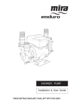
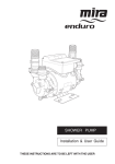
SHOWER PUMP Installation and User Guide These instructions are to be left with the user 1 Contents IMPORTANT SAFETY INFORMATION..................................................... 3 WARNING!............................................................................................ 3 CAUTION!............................................................................................. 4 Introduction........................................................................................ 5 DESCRIPTION........................................................................................... 5 Pump Location...................................................................................... 5 OPERATION.............................................................................................. 6 PACK CONTENTS..................................................................................... 6 Documentation...................................................................................... 6 DIMENSIONS............................................................................................. 7 SPECIFICATIONS..................................................................................... 8 INSTALLATION........................................................................................ 10 Plumbing............................................................................................. 10 Plumbing - push-in connectors............................................................ 15 Electrical.............................................................................................. 16 Earthing............................................................................................... 17 COMMISSIONING................................................................................... 18 FAULT DIAGNOSIS................................................................................. 19 MAINTENANCE....................................................................................... 22 General............................................................................................... 22 Storage................................................................................................ 22 DECLARATION OF CONFORMITY........................................................ 22 SPARE PARTS........................................................................................ 23 Spare Parts List................................................................................... 23 Spare Parts Diagram........................................................................... 23 Customer Service............................................................................ 24 2 IMPORTANT SAFETY INFORMATION 1. 2. 3. 4. 5. 6. 7. 8. 9. 10. 11. 12. WARNING! Products manufactured by us are safe and without risk provided they are installed, used and maintained in good working order in accordance with our instructions and recommendations. This Appliance must be earthed. ENSURE SUPPLEMENTARY BONDING COMPLIES WITH THE "REQUIREMENTS FOR ELECTRICAL INSTALLATIONS". In accordance with the current edition of ‘The Plugs and Sockets (Safety) Regulations' in force at the time of installation, this Mira Enduro is intended to be permanently connected to the fixed electrical wiring of the mains system. The Mira Enduro must not be fitted where it may be exposed to freezing conditions. Make sure that any pipework that could become frozen is properly insulated. DO NOT operate the Mira Enduro if it is frozen. Allow the Mira Enduro to thaw before using again. DO NOT operate the Mira Enduro if water leaks from the unit, maintenance will be required before the Mira Enduro can be safely used. DO NOT allow the Mira Enduro to be run dry. DO NOT run the pump without the guards and covers correctly fitted. Do not obstruct the flow of air around the motor and it must be dust free as the pump motor is air cooled. The inclusion of a Residual Current Device (RCD) (Earth trip) with a trip current of 30 mA is recommended. This may already be part of the consumer unit. There are no user serviceable components beneath the cover of the Mira Enduro. Only a competent tradesperson should remove the cover. If any of the following conditions occur, isolate the electricity and water supplies: 11.1. If the guards and covers are not correctly fitted and water has entered. 11.2. If the guards or covers are damaged. 11.3. If the Mira Enduro begins to make an odd noise, smell or smoke. 11.4. If the Mira Enduro shows signs of a distinct change in performance, indicating a need for maintenance. 11.5. If the Mira Enduro is frozen. Contact Customer Service, refer to the back page of this guide for details. Turn off the electrical and water supplies before removing guards or covers. The electricity must be turned off at the mains and the appropriate circuit fuse removed, if applicable. 3 13. 14. 15. 16. Mains connections are exposed when the guards and covers are removed. Moving parts are exposed when the guards and covers are removed. Refer to the wiring diagram before making any electrical connections. Ensure all electrical connections are tight, to prevent overheating. CAUTION! 1. 2. 3. 4. 5. 6. 7. 8. 9. Read all of these instructions and retain this guide for later use. Pass on this guide in the event of change of ownership of the installation site. Follow all warnings, cautions and instructions contained in this guide. Follow all warnings, cautions and instructions contained on or inside the Mira Enduro. The electrical installation must comply with the “Requirements for Electrical Installations” commonly referred to as the IEE Wiring Regulations, or any particular regulations and practices specified by the local electricity supply company, in force at the time of installation. The installation should be carried out by an electrician or contractor who is registered or is a member of an association such as: 5.1. National Inspection Council for Electrical Installation and Contracting (NICEIC), throughout the UK. 5.2. The Electrical Contractors Association (ECA), England and Wales. 5.3. The Electrical Contractors Association of Scotland (ECAS). The plumbing installation must comply with Water Supply Regulations/Bye‑laws (Scotland), Building Regulations or any particular regulations and practices, specified by the local water company or water undertakers. The installation should be carried out by a plumber or contractor who is registered, or is a member of, an association such as: 6.1. Institute of Plumbing (IPHE), throughout the UK. 6.2. National Association of Plumbing, Heating and Mechanical Services Contractors (NAPH & MSC), England and Wales. 6.3. Scottish and Northern Ireland Plumbing Employers’ Federation (SNIPEF), Scotland and Northern Ireland. System configurations or pump applications other than those shown (refer to Figures 2, 3 and 4) may cause inefficient or impaired operation of the system, which may damage the pump unit. If the system configurations shown are not possible, consult Kohler Mira for advice before commencing installation. Anyone who may have difficulty understanding or operating the controls of any shower should be attended whilst showering. Particular consideration should be given to the young, the elderly, the infirm, or anyone inexperienced in the correct operation of the controls. When the Mira Enduro has reached the end of its serviceable life, it should be disposed of in a safe manner, in accordance with current local authority recycling, or waste disposal policy. 4 Introduction Thank you for purchasing a quality Mira product. To enjoy the full potential of your new product, please take time to read this guide thoroughly, having done so, keep it safe for future reference. DESCRIPTION The Mira Enduro twin impeller regenerative pump is designed to receive a hot and cold gravity supply and provide a pressurised hot and cold supply to a mixing valve, refer to Figures 2, 3 and 4. Pump Location The pump is more effective when pushing water along a pipe rather than pulling. Thus the pump is best positioned as close to the hot water or blend water source as possible to reduce cavitation (air bubbles) in the pipes. The greater the static (inlet) water pressure on the pump the better it will operate (refer to the 'Mira Enduro Shower Pump Performance Graph'). Thus positioning a pump at high level is not advantageous, and may result in inferior performance. If it is not possible to locate the pump in the preferred area due to site limitations and it is necessary to position the pump at high level, or in a position above the secondary tapping that feeds the pump, then there is an increased risk of air locks. This risk must be eliminated. Due consideration should be given to the pump position as any noise generated may be amplified by installation conditions such as reverberant panels, bare floorboards, etc. Make sure adequate free ventilation is provided (minimum clearance of 80 mm around all sides of pump). The hot water storage temperature should not exceed 60 oC. Operation at this temperature will also reduce the rate of formation of limescale in the system. The stored hot and cold water volumes should be sufficient for the required duty, typical flow rates for a shower outlet are 10 l/min. Instantaneous or combination heaters are not suitable. It is not recommended that other services use the same feed pipework as the mixer valve or pump unit as operation problems may occur. 5 OPERATION The pump would normally start automatically when the mixing valve is set to open. When the flow rate through the outlet pipe is more than 0.6 l/min a magnetic float lifts and closes the contacts of the flow switch sensor. When this occurs the electrical circuit to the motor is completed and the pump operates. The opposite action occurs when the flow stops. A vertical distance of 100 mm between the water discharge point of the shower outlet and the base of the cistern would typically achieve the flow rate required. However, long pipe runs or restrictive terminal fittings will increase the gravity head required to produce the required flow. To overcome an initial low flow rate in the outlet pipe, it is possible to by-pass the function of the flow switch by the addition of a momentary action switch connected in parallel with the flow switch (as shown in Figure 8). When the mixing valve is set to on and the switch operated, the pump will run. The pump will maintain the necessary flow rate in the outlet pipe and will continue to operate until the mixing valve is set to off. PACK CONTENTS Examine the contents of the pack and tick the appropriate boxes to familiarise yourself with the part names and to confirm that all parts are included. 1 x Mira Enduro Pump 4 x Flexible Hoses Documentation 4 x Fibre Washer 1 x Installation and User Guide 1 x Customer Support Brochure 6 DIMENSIONS 102 204 204 174 154 96 132 265 All dimensions are nominal and in millimetres Figure 1 7 SPECIFICATIONS 1. 2. 3. 4. 5. Weight Mira Enduro Shower Pump = 7.7 kg (Packed) Ambient Temperature The ambient temperature around the pump must not exceed 40 oC. Electrical 3.1 Protection - the motor is fitted with a self-resetting thermal overload trip. Enclosure protection to IP22, Class F insulation. 3.2 Duty - continuously rated. 3.3 Power Supply - single phase 230 - 240 V, 50 Hz fused supply through a double pole, switched connection unit fitted with a 5 A fuse and with a minimum of 3 mm contact separation gap between terminals. 3.4 Absorbed Power - approximately 420 W at 1.8 amps. Water 4.1 Maximum Hot Water Temperature - 65 oC. The use of hot water above 60 oC is not recommended as this may lead to an increased risk of cavitation, (air bubbles) which increases the pump noise generated and can lead to a reduction in the ultimate service life. It is recommended that the stored temperature of water should never exceed 65 oC. A stored water temperature of 60 oC is considered sufficient to meet all normal requirements and will minimize the deposition of scale in hard water areas. 4.2 Delivery Rates - See Pump Performance Graph. This is for the pump with external flow switch only. Terminal fittings and associated pipe work will reduce this figure. 4.3 Inlet Pressure - Minimum inlet static pressure 0.1 bar must be maintained at all times. Maximum static inlet pressure 1.4 bar. Standards and Approvals The Mira Enduro complies with all relevant directives for CE marking. 8 20 HEAD (Metres) 15 10 5 0 0 10 20 30 40 50 60 FLOW (l/min) Mira Enduro Shower Pump Performance Graph 6. Plumbing Connections 6.1. Inlet and outlet - Kohler Mira recommend only the use of their 22 mm flexible hoses. The hose is fitted with plastic push-in connectors on one end, which must only be connected with the following: a) 22 mm diameter copper pipe to BS EN 1057-R250 (half hard) - Table 3. b) 22 mm plastic pipe to BS 7291 part 1 and part 2 (Table 1) or part 3 (Table 1) plus internal support sleeve. Note! The internal bore of the plastic pipe must be supported against collapse with the pipe manufacturers recommended support sleeve (pipe insert). c) Appropriate plumbing fittings from the John Guest 'speedfit' push-in plumbing fitting range. Note! Other manufacturers fittings are not necessarily compatible and may not provide a water tight connection. 9 INSTALLATION Key to symbols used in the system layouts: Check Valve Servicing Valve Pressure Switch Mixing Valve Pressure Accumulator Float Type Automatic Air Vent (Bottle Valve) Float Operated Valve Shower Handset DHW Fixed Shower Head Domestic Hot Water 15 mm Diameter Pipe 22 mm Diameter Pipe Plumbing Installation must be carried out in accordance with these instructions, and must be conducted by designated, qualified and competent personnel. 1. ATTENTION! Damage is likely to occur to the pump unit if it is allowed to run dry. A minimum pump inlet head pressure of 1 metre must be ensured at all times. 2. Do not fit a non return valve in suction line (inlet) pipework to the pump. The pump must be free to vent to the supply tanks at all times. 3. Pressure loss throughout the inlet pipework network must be kept to the minimum possible to avoid operational difficulties. This will mean the use of shortest pipe‑runs, adequately sized for the maximum flow demand, and with the minimum of restriction through elbows and fittings. Long pipe-runs should be avoided and are best reserved for pipework from the pump outlet to shower fittings. 4. Pipework configurations which can allow air locks to form should be avoided. For inlet pipework, this should be achieved by utilising pipe-runs with a continuous fall. For outlet pipework, either provide a continuously rising pipe‑run, or if an "up and over" pipe-run is unavoidable, fit a float type automatic air vent at the highest point as shown in Figure 3 and 4. 5. The pump must be sited as low as possible in relation to the water source and mounted in a horizontal position with the outlet connection vertically upwards. The operation of the flow switch will be impaired in any other position. 10 6. 7. 8. 9. The hot feed from the cylinder must be as illustrated in Figure 2. Side entry cylinder bosses are not recommended. A drop in cylinder water level could expose a top entry immersion element. Air in water gathers at the edge of the cylinder, and in the centre, during the heating process, before travelling up the vent. Water pumps can develop leaks and should, therefore, not be located where seepage may go undetected or cause damage. The pump must be installed such that it is accessible for servicing or removal. When servicing or disconnecting, small amounts of water may drain from the unit and pipework. Care should be taken when using soldering flux. Protect the pump from damage whilst making soldered connections as some fluxes cause damage to plastic components. It is recommended that inlet and outlet isolation valves (eg. gate valves) are fitted to permit isolation of the pump for servicing. 25 mm Warning Pipe (Overflow) Cold Feed to Mixing Valve DHW Cylinder Feed Cistern Minimum 1.5 m with other simultaneous hot water services 90° 30 to 60° Air Separation Connections DHW Pump Other Hot Water Services System Layout for Mira Enduro Pump Figure 2 11 Cistern Mixing Valve DHW Pump System Layout for Mira Enduro Pump Figure 3 Cistern DHW Pump Mixing Valve System Layout for Mira Enduro Pump Figure 4 12 10. 11. 12. 13. 14. 15. Care should be taken to ensure that all pipework fittings and connections are secure. This is particularly important on the pump inlet pipework network, due to the potential for air to be drawn into the system should suction conditions exist. All connection pipework must be adequately and rigidly supported. The flexible hoses supplied are primarily for vibration isolation, and should be installed straight. They may be bent to a maximum of 30o, in which case they must be allowed to form a uniform swept curve, and must not be stressed in any way by the plumbing configuration. The pump motor is air cooled and it is important that the flow of air is not impeded around the appliance. Damage to fabrics may occur if allowed to foul the motor air vents - avoid a position in which the product could become frozen. Do not rigidly secure pump unit to the mounting surface. Install inlet and outlet pipework to meet pump flexible hoses, flush through pipework fully before connecting to pump, and then complete plumbing installation. Cistern Pump Mixing Valve DHW Unsuitable Layout for Mira Enduro Pump Figure 5 13 Cistern Mixing Valve Pump DHW Unsuitable Layout for Mira Enduro Pump Figure 6 Cistern Pump Mixing Valve DHW Unsuitable Layout for Mira Enduro Pump Figure 7 14 Plumbing - push-in connectors Do not use stainless steel, chrome or nickel plated pipe with the flexible hose push‑in plumbing connections. Do not introduce solder flux into the joint or surrounding area, as plastics will be attacked and may fail. All solder joints should be completed before final connection to push-in connections, on the flexible hose. Flux residues must be removed. Do not allow contact with oil or cellulose based paints, paint thinners or strippers, acid based descalents or aggressive cleaning agents. 1. Make sure that the pipe is free from all score marks and deformities in the area of the insertion depth and cut the pipe square removing all burrs and sharp edges to prevent damage to the 'O' seal. 2. Before inserting the pipe into the fitting, mark the insert depth on the wall of the pipe with a soft pencil at a distance of 33 mm from the end to be inserted (refer to illustration). 3. Check in the mouth of the fitting that the 'O' seal, nylon washer and collet are in position (refer to illustration). Nylon Washer 22 mm Pipe Collet 'O' Seal Pencil Mark Insertion Depth 33 mm Pipe Stop Hose 4. 5. Push the pipe firmly into the fitting, until the pencil mark is level with the top of the collet and the pipe stop resistance is felt. Pull on the pipe to make sure that it is secure and fitted correctly. To release the joint, push the pipe firmly into the fitting, hold the collet down and gently remove the pipe. Caution! Be careful when draining any residual water. 15 Electrical Before starting work on the electrical installation, make sure that the power supply is isolated. Cable selection and corresponding fuse size should be chosen in accordance with the current involved and surrounding conditions. All electrical installation work should be carried out by a competent person. 1. The unit is fitted with 1.3 metres of supply cable. Should this cable be too short, a suitable length of three-core cable (minimum 0.75 mm per core) should be obtained and connected to the terminal block in the electrical box (refer to Figure 8). Remove the electrical box cover by unscrewing the four retaining screws. The supply cable and internal wiring within the terminal box are routed and secured for compliance with the electrical standard EN60335-1. After replacing the supply cable, make sure that the factory routing and securing of all wiring is always maintained as shown in Figure 9. Do not use long cable lengths, as this may cause substantial voltage drop, poor pump performance, and could also result in motor overload. BLUE MAIN WINDING N A START WINDING M N S1 S2 S2 S1 L CAPACITOR BLACK BROWN THERMOTRIP BLUE 2. BLUE N BROWN L GREEN / YELLOW E FLOWSWITCH REED (S2) OPTIONAL ALTERNATIVE START METHOD e.g. Momentary Action Switch FLOWSWITCH REED (S1) Schematic Wiring Diagram Figure 8 16 230 V AC 1 Ph/50 Hz SUPPLY BLUE (Link Wire) BLACK BLUE BROWN BLUE (N) BROWN (L) S2 S2 N A M IMPORTANT CABLE SHOULD BE ROUTED AS SHOWN. END OF OUTER SHEATH TO BE LEVEL WITH TERMINAL BLOCK, AS SHOWN S1 S1 FLOWSWITCH REED LEADS SUPPLY LEAD FLOWSWITCH FLOWSWITCH REED REED Earthing Upper Electrical Box - Wiring Diagram Figure 9 This appliance must be earthed via the supply cord, which must be correctly connected to the earth point located in the terminal box. Copper or metallic pipework must have supplementary earth bonding where the continuity has been broken by flexible hoses or plastic components. Adjacent suction and delivery pipes should be fitted with earthing clamps to BS 951 and connected with earthing wire size 4 mm² (refer to the following illustration). Certain installations may require additional earthing arrangements such as equipotential bonding. Reference should be made to the relevant regulations concerning this subject to make sure of compliance. Diagram of earth continuity connections 17 COMMISSIONING Commissioning must be carried out in accordance with these instructions, and must be conducted by designated, qualified and competent personnel. 1. Make sure the pump is isolated electrically. 2. Make sure that all isolating valves are fully open and the pump chamber is flooded. 3. Open an outlet (e.g. shower control). Water should flow from the outlet under pressure of gravity. Leave an outlet open for a short period to allow air to be expelled from system. ATTENTION! The flow rate must be at least 0.6 l/min for the flow switch to operation. 4. Close the outlet. 5. Switch on the power supply to the pump. (If the pump operates, repeat the commissioning steps 1 - 4, if this fails refer to the Fault Diagnosis). 6. 7. WARNING! The motor casing can become very hot under normal operating conditions. Care must be taken to make sure that it cannot be touched or covered, during normal operation. Open an outlet and check that the pump operates automatically. If the pump does not operate, repeat the commissioning procedure, refer to Fault Diagnosis. 18 FAULT DIAGNOSIS Symptom 1. Pump does not (a) start. Cause No power supply. 1. (b) No/low flow 1. through terminal fittings (flow switch 2. needs typically 3. 0.6 l/min). 4. 5. (c) Internal problem. 1. 2. 3. The pump has (d) been in use and stopped within a short period. 2. The pump (a) operates momentarily when not required. (b) Motor thermal 1. switch tripped. Flow-switch operating due to water movement in pipework. 1. Flow-switch reed/PCB tripping. 1. 2. 19 Rectification Check all fuses and RCD. Make sure power supply is available at the pump terminal box. If fuse "blows" repeatedly, refer to symptom 6 (b). Clean the shower heads and make sure the flow controls are operating correctly. Check for air locks. Check the isolating valves are fully open and other restrictions. Check the system has adequate static head and flow potential, refer to Operation. The flow switch mechanism is sticking. (New installation). Check the wiring in the electrical boxes, refer to Figure 8. Check continuity of the flow‑switch reed, refer to Note 1 at end of this section. Pump impeded internally, refer to symptom 6 (b). Allow the motor to cool, up to 1 hour, refer to symptom 6 (c). Air pocket after pump. Locate and make sure adequate venting. Air pocket in the pump supply (hot) expanding due to system heating. Correct pipework layout to eliminate thermal flow, fit a single check valve close to and after pump outlet, refer to Note 2 at end of this section. Local source of strong electromagnetic/radio transmission. Shield flow-switch reed (tinfoil). Symptom 3. Pumped (a) flow/pressure is initially adequate, but reduces after short time. Cause Water supply fault. 1. 2. 3. 4. The pump is noisy in operation. N.B. All pumps generate some noise. Installation conditions may allow this to be amplified. (a) Installation fault. 1. 2. (b) Pump impeded 1. internally. 2. 3. 5. The pump (a) switches off while in use. (b) (c) Power supply fault. 1. Water supply 1. fault. Motor thermal 1. switch tripped. 2. 3. 4. 20 Rectification Check that hot and cold storage volumes are sufficient for demand. Check that all supply strainers (including the mixing valve) are clean. Pipework configuration and/or water supply conditions are causing air induction. Vibration from the pump body transmitted through reverberant material. Check the pump position and pipework securings. Note! The pump should be free standing on its rubber feet, and not screwed down. Fault in the supply to the pump, refer to symptom 3. Check for debris and/or damage in impeller housing. Mechanical seal worn/damaged. Renew. Motor fault, refer to symptom 5 (d). Check all fuses and RCD. Make sure the power supply is available at the pump terminal box. Refer to symptom 3. Allow the motor to cool, up to 1 hour. Check the ambient air temperature around the pump does not exceed 40 oC. Make sure adequate free ventilation is provided (minimum clearance of 80 mm around all sides of the pump). Pump impeded internally, refer to symptom 4(b). Symptom 5. Pump switches (d) off while in use (continued) 6. Leak from the (a) pump housing. Cause Motor fault. Rectification Contact Customer Service, refer to the back page of this guide for details. Seal worn/ damaged. 1. 2. (b) Inlet pressure above maximum permitted. 1. If the leak is from rear of the impeller housing at junction with the motor assembly, the mechanical seal requires renewal. If the leak is from the perimeter of the impeller housing, then the housing seals require renewal. Refer to Specifications. Note 1.The flow-switch continuity should be checked with the power switched off and one flow-switch lead disconnected. Use appropriate continuity meter. Correct operation is open circuit with no flow, and closed circuit with flow. Note 2.Fitting a check valve is a secondary measure, initially the cause of water surge should be investigated and rectified. The single check valve should be of spring‑loaded pattern and fitted in the discharge pipework. This may increase the minimum head pressure required to operate the flow-switch. 21 General MAINTENANCE Mira products are precision-engineered and should give continued superior and safe performance. Providing that the pump has been correctly installed and operated as advised in this booklet, difficulties should not arise. WARNING! ISOLATE POWER SUPPLY BEFORE REMOVING THE PUMP TERMINAL BOX COVER. Components are precision-made, so care must be taken during servicing to avoid damage. When ordering spare parts, please state product type, i.e. Mira Enduro, and identify part name and number (refer to Spare Parts List). Regular (preventative) maintenance is not required. The fault diagnosis section should determine the cause and rectification for any difficulty experienced with the operation of this pump. If further assistance is required, contact Customer Service, refer to the back page of this guide for details. Storage If this product is not installed immediately upon receipt, make sure that it is stored in a dry, frost and vibration free environment in its original packing. DECLARATION OF CONFORMITY DECLARATION OF CONFORMITY 98/37/EC BS EN ISO 12100-1, BS EN ISO 12100-2, BS EN 809 2006/95/EC BS EN 60335-1, BS EN 60335-2-41, EN 50366 2004/108/EC BS EN 55014-1, BS EN 55014-2, BS EN 55022, BS EN 61000-3-2, BS EN 61000-3-3, BS EN 61000-4-2, BS EN 61000-4-3, BS EN 61000-4-4, BS EN 61000-4-5, BS EN 61000-4-6, BS EN 61000-4-11 IT IS HEREBY CERTIFIED THAT THE STUART ELECTRIC MOTOR DRIVEN PUMP AS SERIAL NUMBER BELOW, COMPLIES WITH THE ESSENTIAL REQUIREMENTS OF THE ABOVE E.E.C. DIRECTIVES. RESPONSIBLE PERSON AND MANUFACTURER STUART TURNER LIMITED HENLEY-ON-THAMES, OXFORDSHIRE RG9 2AD ENGLAND. Signed . . . . . . . . . . . . . . . . . . . . . . . . . . . . . . . . . . . . . . . . . . . . . . . . . . Quality Manager Stuart Turner are an approved company to BS EN ISO 9001:2000 Manufactured on behalf of Kohler Mira by Stuart Turner Ltd, Henley-on-Thames, Oxfordshire RG9 2AD 22 SPARE PARTS Spare Parts List 465.01 465.02 465.03 465.04 465.05 465.06 465.08 465.09 465.11 872.56 1587.002 'O' Seal Pack - including Mechanical Seal (components identified 'A') Flow Switch Module Flow Switch Mechanism Flexible Hose Assembly Rubber Feet Screw Pack (not illustrated) Impeller Assembly Push Fit Pack (for flexible hose) Inlet Housing Connector Cable Tie Motor Control PCB (not illustrated) Spare Parts Diagram 465.04 465.09 465.11 465.06 A 465.03 465.02 465.04 465.05 465.03 465.08 465.02 465.03 872.56 A 465.08 A 465.06 23 465.03 465.04 A Customer Service Guarantee of Quality Mira Showers guarantee your product against any defect in materials or workmanship, provided that it is installed and maintained in accordance with the instructions given in this guide. To validate the guarantee, please return your completed registration card within 30 days of product installation. Within the guarantee period we will resolve defects, free of charge, by repairing or replacing parts or modules as we may choose. To be free of charge, service work must only be undertaken by Mira Showers or our approved agents. Service under this guarantee does not affect the expiry date of the guarantee. The guarantee on any exchanged parts or product ends when the normal product guarantee period expires. Not covered by this guarantee: Planned maintenance, or replacement parts required to comply with the servicing requirements of the TMV 2 and TMV 3 healthcare schemes (where applicable). Damage or defects arising from incorrect installation, improper use or lack of maintenance, including build-up of limescale. Damage or defects if the product is taken apart, repaired or modified by any persons not authorised by Mira Showers or our approved agents. This guarantee is in addition to your statutory and other legal rights. What to do if something goes wrong If when you first use your shower, it doesn’t function correctly, first contact your installer to check that installation and commissioning are satisfactory and in accordance with the instructions in this manual. We are on hand to offer you or your installer any advice you may need. Should this not resolve the difficulty, simply contact our Customer Services Team who will give every assistance and, if necessary, arrange for our service engineer to visit. If the performance of your shower declines, consult this manual to see whether simple home maintenance is required. Please call our Customer Services Team to talk the difficulty through, request a service under guarantee if applicable, or take advantage of our comprehensive After-Sales service. As part of our quality and training programme calls may be recorded or monitored. Our Customer Services Team is comprehensively trained to provide every assistance you may need: help and advice, spare parts or a service visit. Spare Parts We maintain an extensive stock of spares and aim to provide support throughout the product’s expected life. Genuine Mira spares can be purchased direct from Customer Services or from approved stockists or merchants (locations on request). Spare parts will normally be despatched within two working days. Payment can be made using most major Credit or Debit cards at the time of ordering. Should payment by cheque be preferred, a pro-forma invoice will be sent. All spares are guaranteed for 12 months from the date of purchase. Spares that have been supplied directly from us can be returned within one month from the date of purchase, providing that they are in good order and the packaging is unopened. Note! Returned spares will be subject to a 15% restocking charge and authorisation must be obtained before return. Please contact our Customer Services Team. Note! In the interests of safety, spares requiring exposure to mains voltages should only be fitted by competent persons. Service / Repairs Our Service Force is available to provide a quality service at a reasonable cost. You will have the assurance of a Mira trained engineer/agent, genuine Mira spare parts and a 12 month guarantee on the repair. Payment should be made directly to the engineer/agent who will accept most major Credit or Debit cards or a cheque supported by a banker’s card. To Contact Us England, Scotland, Wales and Northern Ireland Mira Showers Customer Services Telephone: 0844 571 5000 E-mail: [email protected] Fax: 01242 282595 By Post: Cromwell Road, Cheltenham, Gloucestershire, GL52 5EP Eire Modern Plant Ltd (Dublin) Telephone: 01 459 1344 E-mail: [email protected] Fax: Dublin 01 459 2329 Post: Otter House, Naas Road, Clondalkin, Dublin 22 Mira is a registered trade mark of Kohler Mira Limited. The company reserves the right to alter product specifications without notice. www.mirashowers.co.uk 1074846_W2_D (P81B) 18719 2209/1-04 24 © Kohler Mira Limited, August 2009