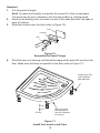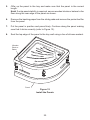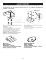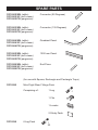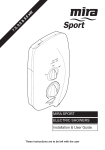
1
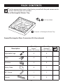
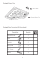
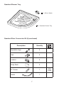
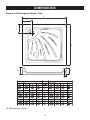
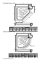
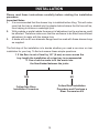
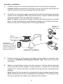
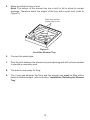
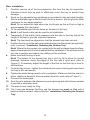
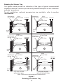
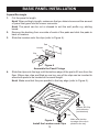
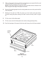
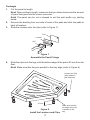
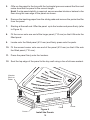
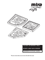
Flight Shower Tray
Riser and Non-Riser
Installation & User Guide
These instructions are to be left with the user
1
Contents
Introduction.............................................................................................. 3
Guarantee............................................................................................. 3
Patents.................................................................................................. 3
Important Safety Information.................................................................. 4
Pack Contents.......................................................................................... 5
Square or Rectangular Shower Tray..................................................... 5
Pentangle Shower Tray......................................................................... 6
Quadrant Shower Tray.......................................................................... 7
Dimensions............................................................................................... 8
Square or Rectangular Shower Tray..................................................... 8
Pentangle Shower Tray......................................................................... 9
Quadrant Shower Tray.......................................................................... 9
Installation.............................................................................................. 10
Non-Riser Installation.......................................................................... 11
Riser Installation.................................................................................. 13
Rebating the Shower Tray................................................................... 14
Basic Panel Installation ........................................................................ 15
Square/Rectangle................................................................................ 15
Pentangle............................................................................................ 17
Quadrant............................................................................................. 19
Maintenance............................................................................................ 21
General................................................................................................ 21
Cleaning.............................................................................................. 21
Accessories............................................................................................ 22
Spare Parts............................................................................................. 23
Customer Service.....................................................................Back Page
2
Introduction
Thank you for purchasing a quality product. To enjoy the full potential of your new
shower tray, please take time to read this guide thoroughly, and keep it handy for
future reference.
Important! The shower trays featured in this manual are available for use as riser
and non-riser products. Carefully unpack and check the tray for colour, size, general
acceptability and compatibility with the shower enclosure and other bathroom
furniture. Check for transit damage and report any faults immediately to your supplier.
No claims for the above will be considered after installation.
Mira Flight Shower Trays - are available in various shapes and sizes with or without
upstands and are all supplied with an 85 mm top access waste and trap.
Mira Flight Riser Conversion Kit - comprises of adjustable legs, panels, panel
securing clips, corners and optional end pieces. Riser Conversion Kits are available
to purchase separately.
Mira Flight Offset Leg Adaptor Fittings Kit - for use with the Mira Flight Riser
Conversion Kit, the Offset Leg Adaptor allows the installation of pipework behind the
adjustable legs. Offset Leg Adaptor Fittings Kits are available to purchase separately
(refer to section: ‘Accessories’).
Mira Flight Upstand Tiling Strip - Upstand Tiling Strips are available to purchase
separately (refer to section: ‘Accessories’).
Guarantee
Mira Showers guarantee the Mira Flight Shower Tray against any defect in materials
or workmanship for a period of ten years from the date of purchase.
For terms and conditions refer to the back cover of this guide.
Recommended Usage
Domestic
ü
Light Commercial
ü
Heavy Commercial
ü
Healthcare
ü
Patents
Patent Applications
GB:
0526168
Euro: 1667562
3
Important Safety Information
Caution! These products are precision-engineered and should give continued
superior performance, provided:
1.They are installed and maintained in accordance with the recommendations
given in this manual.
2. Periodic attention is given, as necessary, to maintain the product in good
functional order. Recommended guidelines are given in the Maintenance
section.
Warning! The Mira Flight 760 and 800 variants weigh less than 25 kg and are a
‘one‑person-lift’. All other Mira Flight tray variants weigh in excess of 25 kg and
will require a ‘two-person-lift’.
4
Pack Contents
Tick the appropriate boxes to familiarise yourself with the part names and to
confirm that the parts are included.
Square or Rectangular Shower Tray
1 x 85 mm Waste
1 x Square or Rectangular Shower Tray
Square/Rectangular Riser Conversion Kit (if purchased)
Description
Quantity
Quantity
Square
or 900 x 760 rectangle
Rectangle
all other rectangles
Adjustable Legs
4
6
Clips
4
6
Locators
4
6
Sticky Pads
5
7
90° Corner
1
1
Panels
2
2
5
Pentangle Shower Tray
1 x 85 mm Waste
1 x Pentangle Shower Tray
Pentangle Riser Conversion Kit (if purchased)
Description
Quantity
Adjustable Legs
5
Clips
5
Locators
5
Sticky Pads
6
135° Corner
2
Panels
3
6
Quadrant Shower Tray
1 x 85 mm Waste
1 x Quadrant Shower Tray
Quadrant Riser Conversion Kit (if purchased)
Description
Quantity
Adjustable Legs
4
Clips
4
Locators
4
Sticky Pads
5
90° Corner
1
Panels
1
7
Not
Used
Dimensions
Square or Rectangular Shower Tray
A
C
C
B
112
90
D
All Dimensions in mm
8
Pentangle Shower Tray
A
C
C
410
B
707
410
112
90
D
Quadrant Shower Tray
A
C
C
B
Radius 550
112
90
D
All Dimensions in mm
9
Installation
Please read these instructions carefully before starting the installation
procedure.
Important Notes
1. It is recommended that the shower tray is installed before tiling. This will make
sure that the tray is rebated into the plaster behind where the tile face will be,
thus helping to achieve a watertight joint.
2.With a rebate or partial rebate the amount of adjustment on the enclosure could
be affected. Therefore make sure that the enclosure to be fitted has sufficient
adjustment to mate with the shower tray.
3. A waste with an 85 mm diameter flange must be used with these shower trays
as supplied.
The first step of the installation is to decide whether you need a non-riser or riser
installation for your tray. To find out answer these simple questions.
1. If the floor is out of level by 1/4” (6 mm) or more across the
tray length the installation of a riser tray is recommended
2. Can a hole be made to fit the waste into
the floor/timber/between the joists
YES
NO
Follow Non-Riser
Installation Procedure
Follow Riser Installation
Procedure and Purchase a
Riser Conversion Kit
10
Non-Riser Installation
1.
Carefully remove all of the blue protective film from the tray for inspection.
Caution! Additional protective coverings such as a dust sheet should then be
used to protect the tray from damage from falling objects.
2.
Fit the 85 mm top access waste (supplied) to the tray before setting down being
careful not to overtighten. Make sure that the seal is in place. Additional beads
of silicone sealant must be used (refer to Figure 1).
Note! To tighten, remove the Shower Grid from the Flange and turn it upside
down. Locate it into the slots on the flange and tighten in a clockwise direction.
Remove and refit the Shower Grid to it’s original position.
Shower Grid
(invert to
tighten flange)
Bead of
Silicone Sealant
Flange
For Non-Riser
Installations coat the
underside of the tray with
silicone sealant, a tiling
cement or a weak mix of
sand and cement (5:1)
Seal
Figure 1
Install the Tray Waste
3.
Position the tray up to the walls and rebate into the plaster as required, refer
to section: ‘Installation, Rebating the Shower Tray’. Remove the tray from
its position.
4.
Make sure that the floor is clean, dry, firm and level. Coat the ribbed underside
of the tray with silicone sealant, a tiling cement or a weak mix of sand and
cement (5:1). Then press down into place ensuring the tray is positioned into
rebates.
Note! Where the tray comes into contact with the wall or plaster board surface,
apply a liberal amount of silicone sealant before installation. This will help secure
the tray in position and reduce any rubbing of the surfaces.
11
5.
Make sure that the tray is level.
Note! The bottom of the shower tray has a built in fall to allow for correct
drainage. Therefore check the edges of the tray with a spirit level (refer to
Figure 2).
Make sure that the
shower tray is level
Figure 2
Level the Shower Tray
6.
Connect the waste pipe.
7.Seal the joint between the shower tray and adjoining wall with silicone sealant
to provide a secondary seal.
8.The area is now ready for tiling.
9.
The 3 mm gap between the tiling and the shower tray must be filled with a
bead of silicone sealant, refer to section: ‘Installation, Rebating the Shower
Tray’.
12
Riser Installation
1.
Carefully remove all of the blue protective film from the tray for inspection.
Attention should then be paid to effectively cover the tray to protect from
damage.
2.Spots on the adjustable leg mouldings are provided to help set equal heights.
Set the adjustable legs to the third spot from the bottom, this will give the initial
clearance for the waste supplied.
Note! Do not adjust the legs above the fourth spot as this will be too high to
accommodate the riser panel.
3. Fit the adjustable legs into the holes on the back of the tray.
Note! A soft faced mallet can be used to aid installation.
4. Temporarily fit the waste outlet pipework and the trap to the tray. Adjust the
height of the feet to give the required clearance.
Note! The feet must be adjusted so that the shower tray does not rock.
5. Position the tray up to the walls and rebate the tray into the plaster (as required),
refer to section: ‘Installation, Rebating the Shower Tray’.
Note! Where the tray comes into contact with the wall or plaster board surface,
apply a liberal amount of silicone sealant before installation. This will help secure
the tray in position and reduce any rubbing of the surfaces.
6. Make sure that the tray is level.
Note! The bottom of the shower tray has a built in fall to allow for correct
drainage, therefore check the edges of the tray with a spirit level (refer to
Figure 2). If necessary adjust the height of the feet so that the tray is level in
all directions.
7. Once the tray is level - tighten the individual lock nuts on the leg sets and check
the tray is firm and secure.
8.Tighten the waste being careful not to overtighten. Make sure that the seal is in
place, additional beads of silicone sealant must be used (refer to Figure 1).
9. Connect the waste pipe.
10.Seal the joint between the shower tray and adjoining wall with silicone sealant
to provide a secondary seal.
11.The area is now ready for tiling.
12. The 3 mm gap between the tiling and the shower tray must be filled with a
bead of silicone sealant, refer to section: ‘Installation, Rebating the Shower
Tray’.
13
Rebating the Shower Tray
The figures below provide an indication of the type of typical recommended
installation methods. It does not provide a fully detailed description for ALL installation
methods / procedures.
To aid installation, optional accessories are available, refer to section
‘Accessories’.
Plasterboard
9.5 mm Thick
Plasterboard
9.5 mm Thick
Plasterboard
9.5 mm Thick
Clear Area
Clear Area
Silicone Sealant
Silicone Sealant
Grout
2 mm Thick
16.5 mm
Tile
5 mm Thick
Plasterboard
9.5 mm Thick
Plasterboard
9.5 mm Thick
Grout
2 mm Thick
Tile
5 mm Thick
Clear Area
Clear Area
Silicone Sealant
Silicone Sealant
16.5 mm
Tile
5 mm Thick
Plasterboard
9.5 mm Thick
Grout
2 mm Thick
Tile
5 mm Thick
Clear Area
Clear Area
Silicone Sealant
Silicone Sealant
E
16.5 mm
D
3 mm
Gap
Grout
2 mm Thick
16.5 mm
B
3 mm
Gap
C
3 mm
Gap
Grout
2 mm Thick
Tile
5 mm Thick
A
3 mm
Gap
3 mm
Gap
Grout
2 mm Thick 16.5 mm
Tile
5 mm Thick
3 mm
Gap
F
THIS SIDE SHOWN
THIS SIDE SHOWN
WITH STUD PARTITION
WITH SOLID WALL
Note:- The amount of rebate affects the enclosure size.
Figure 3
Rebating the Shower Tray
14
16.5 mm
Basic Panel Installation
Square/Rectangle
1. Cut the panel to length.
Note! When cutting to length, make sure that you take into account the amount
of panel that goes into the corner connector.
Note! The panel can be cut or shaped to suit the wall profile e.g. skirting
board.
2. Remove the backing from one side of each of the pads and stick the pads to
back of locators.
3.Slide the locators onto the clips (refer to Figure 4).
Pad
Locator
Clip
Figure 4
Assemble the Panel Fixings
4.Slide the clips onto the legs until the bottom edge of the pad is 55 mm from the
floor. Where two clips are fitted on one leg, one of the clips can be inverted to
allow both pads to be located at the same height.
Note! Make sure that they are parallel to the tray edge (refer to Figure 5).
Locator and Clip
(with adhesive
pad attached)
55 mm
Figure 5
Install the Locators and Clips
15
Make sure that the
top edge of the clip is
parallel to the tray
5.
Offer up the panel to the tray with the horizontal grooves nearest the floor and
make sure that the panel is the correct length.
Note! If extra panel stability is required, secure wooden blocks or batons to the
floor along the rear edge of the panel as shown.
6.
Remove the backing paper from the sticky pads and remove the protective film
from the panel.
7.
Starting at the wall end. Offer the panel up to the locator and press firmly.
Continue along the panel making sure that it sticks correctly (refer to Figure
6).
8.
Fit the corner to the other panel.
9.
Fit the corner onto the fixed panel and continue along pressing firmly.
10.Seal the top edge of the panel to the tray wall using a line of silicone sealant.
Wooden
Block or
Baton
Panel
Panel
Corner
Figure 6
Install the Panels
16
Pentangle
1. Cut the panel to length.
Note! When cutting to length, make sure that you take into account the amount
of panel that goes into the corner connector.
Note! The panel can be cut or shaped to suit the wall profile e.g. skirting
board.
2. Remove the backing from one side of each of the pads and stick the pads to
back of locators.
3.Slide the locators onto the clips (refer to Figure 7).
Pad
Locator
Clip
Figure 7
Assemble the Panel Fixings
4.Slide the clips onto the legs until the bottom edge of the pad is 55 mm from the
floor.
Note! Make sure that they are parallel to the tray edge (refer to Figure 8).
Locator and Clip
(with adhesive
pad attached)
55 mm
Figure 8
Install the Locators and Clips
17
Make sure that the
top edge of the clip
is parallel to the
tray.
5.
Offer up the panel to the tray with the horizontal grooves nearest the floor and
make sure that the panel is the correct length.
Note! If extra panel stability is required, secure wooden blocks or batons to the
floor along the rear edge of the panel as shown.
6.
Remove the backing paper from the sticky pads and remove the protective film
from the panel.
7.
Starting at the wall end. Offer the panel up to the locator and press firmly (refer
to Figure 9).
8.
Fit the corner onto one end of the larger panel (710 mm) so that it fits onto the
fitted panel.
9.
Locate onto the fitted panel (410 mm) and firmly press onto the pads.
10. Fit the second corner onto one end of the panel (410 mm) so that it fits onto
the fitted panel (710 mm).
11. Press the panel firmly onto the locators.
12.Seal the top edge of the panel to the tray wall using a line of silicone sealant.
Wooden
Block or
Baton
Corner
Figure 9
Install the Panels
18
Panel
Corner
Quadrant
1. Cut the panel to length.
Note! Cut each end equally to maintain the correct fit of the curved panel.
The panel can be cut or shaped to suit the wall profile e.g. skirting board.
2. Remove the backing from one side of each of the pads and stick the pads to
back of locators.
3.Slide the locators onto the clips (refer to Figure 10).
Pad
Locator
Clip
Figure 10
Assemble the Panel Fixings
4.Slide the clips onto the legs until the bottom edge of the pad is 55 mm from the
floor. Make sure that they are parallel to the floor (refer to Figure 11).
Locator and Clip
(with adhesive
pad attached)
Make sure that
the top edge of
the clip is parallel
to the tray.
55 mm
Figure 11
Install the Locators and Clips
19
5.Offer up the panel to the tray and make sure that the panel is the correct
length.
Note! If extra panel stability is required, secure wooden blocks or batons to the
floor along the rear edge of the panel as shown.
6.
Remove the backing paper from the sticky pads and remove the protective film
from the panel.
7.
Put the panel in position and press firmly. Continue along the panel making
sure that it sticks correctly (refer to Figure 12).
8.
Seal the top edge of the panel to the tray wall using a line of silicone sealant.
Wooden
Block or
Baton
Panel
Figure 12
Install the Panels
20
Maintenance
General
Providing the shower tray has been correctly installed in accordance with the
instructions contained in this guide, difficulties should not arise. If any maintenance
is required then it must be carried out by a competent tradesperson for whom the
maintenance instructions are provided.
Cleaning
It is advised that the shower tray is cleaned immediately after use, to remove any
insoluble products. Hot soapy water should be used and then the tray should be
wiped. Cleaners of gritty or abrasive nature should never be used.
The acrylic ABS surface of this shower tray has good resistance properties to acids
but should not come into contact with alkalis or organic solvents, such as caustic
soda, dry cleaning agents and paint strippers.
21
Accessories
Genuine Mira accessories can be purchased direct from Customers Services (our
contact details can be found on the back cover of this guide) or from approved
stockists or merchants.
Apply Silicone
Sealant
Shower Tray
Offset Leg adaptor
Adjustable Leg
(with locking Nut removed)
Offset Leg Adaptor Fittings Kit (2 off) ‘Patent
Pending’
1570.557 WH (white)
The Offset Leg Adaptor allows the Adjustable
Legs to be installed offset to the tray, thus
allowing installation of pipework behind the
Adjustable Legs (refer to illustration).
Important! Unscrew and remove the Locking
Nut when using the Offset Leg Adaptor.
Upstand Tiling Strip (3 off, 1250 mm long)
1570.558 WH (white)
Eliminates the need to rebate the shower tray
into solid or stud walls.
Shower Seat
White - 2.1536.128
White/Chrome - 2.1536.129
For use in or out of the showering area. Note!
Must be installed onto a solid wall.
Shower seat folds up when not in use
Wall Mounted Soap Dish
White - 1.1540.278
Chrome - 1.1540.279
Wall mounted for use anywhere in, or outside
the showering area.
22
Spare Parts
1570.002 WH (white)
1570.002 SC (soft cream)
1570.002 PG (pergamon)
Connector (90 Degrees)
1570.003 WH (white)
1570.003 SC (soft cream)
1570.003 PG (pergamon)
Connector (135 Degrees)
1570.004 WH (white)
1570.004 SC (soft cream)
1570.004 PG (pergamon)
Quadrant Panel
1570.005 WH (white)
1570.005 SC (soft cream)
1570.005 PG (pergamon)
1200 mm Panel
1570.589 WH (white)End Piece
1570.589 SC (soft cream)
1570.589 PG (pergamon)
(for use with Square, Rectangle and Pentangle Trays)
1570.280
Mira Flight Riser Fittings Pack
Comprising of:
1 Leg
1 Clip
1 Locator
2 Sticky Pads
1570.296
6 Leg Pack
23
Customer Service
Guarantee
Your product has the benefit of our manufacturer’s
guarantee which starts from the date of purchase.
To activate this guarantee, please return your completed
registration card, visit our website or free phone 0800
0731248 within 30 days of purchase (UK only).
Within the guarantee period we will resolve defects in
materials or workmanship, free of charge, by repairing or
replacing parts or product as we may choose.
This guarantee is in addition to your statutory rights
and is subject to the following conditions:
● The product must be installed and maintained in
accordance with the instructions given in this user
guide.
● Servicing must only be undertaken by us or our
appointed representative. Note! if a service visit
is required the product must be fully installed and
connected to services.
● Repair under this guarantee does not extend the original
expiry date. The guarantee on any replacement parts
or product ends at the original expiry date.
● For shower fittings or consumable items we reserve
the right to supply replacement parts only.
The guarantee does not cover:
● Call out charges for non product faults (such as
damage or performance issues arising from incorrect
installation, improper use, lack of maintenance, build up
of limescale, frost damage, corrosion, system debris or
blocked filters) or where no fault has been found with
the product.
● Water or electrical supply, waste and isolation issues.
● Compensation for loss of use of the product or
consequential loss of any kind.
● Damage or defects caused if the product is repaired
or modified by persons not authorised by us or our
appointed representative.
● Routine maintenance or replacement parts to comply
with the requirements of the TMV 2 or TMV 3 healthcare
schemes.
Helpdesk Service
Our dedicated Customer Services Team is comprehensively
trained and can offer help and advice, spare parts,
accessories or a service visit. We will need you to have your
model name or number, power rating (if applicable) and date
of purchase. As part of our quality and training programme
calls may be recorded or monitored.
Mira Showers Website (www.mirashowers.co.uk)
From our website you can register your guarantee,
download additional user guides, diagnose faults, purchase
our full range of accessories and popular spares, refer to
our FAQ’s and request a service visit.
Spares and Accessories
We maintain extensive stocks of genuine spares and
accessories and aim to provide support throughout the
product’s expected life. Payment can be made by phone
at time of order using most major Credit or Debit cards and
we aim to despatch orders within two working days. Items
purchased from us are guaranteed for 12 months from date
of purchase. For safety reasons spares exposed to mains
voltages should only be fitted by competent persons.
Returns – items can be returned within one month of date of
purchase, providing that they are in good condition and the
packaging is unopened. Please obtain authorisation from
our Customer Services Team before return. We reserve the
right to apply a 15% restocking charge.
Service / Repairs
We have a nationwide team of Service Technicians who can
carry out all service or repair work to your product within the
guarantee period and beyond. You have the assurance of a
fully trained Mira Technician, genuine Mira spare parts and
a 12 month guarantee on any chargeable work done.
Payment should be made directly to the Service Technician
who will accept most major Credit or Debit cards.
To Contact Us
UK
Telephone: 0844 571 5000
Mon to Fri 8:00 am - 5:30 pm, Sat 8:30 am - 3:30 pm
E-mail: [email protected]
If your product does not function correctly when you first Fax: 01242 282595
use it, contact your installer to check that it is installed By Post: Mira Customer Services Dept, Cromwell Road,
and commissioned in accordance with the instructions in Cheltenham, Gloucestershire, GL52 5EP
this manual.
Should this not resolve the issue, contact our Customer Eire
Services Team who will offer you or your installer advice and Telephone: 01 459 1344
if applicable arrange for a Service Technician to call.
Mon to Fri 9:00 am - 5:00 pm
If the performance of your product declines, check in this E-mail: [email protected]
manual to see if simple home maintenance is required. If Fax: Dublin 01 459 2329
you require further assistance call our Customer Services
By Post: Modern Plant Ltd (Dublin),
Team.
Otter House, Naas Road, Clondalkin, Dublin 22
What to do if something goes wrong
Extended Guarantees
A selection of protection plans are available that
enable you to cover repair bills for the life of your policy
(excludes Eire). Ring 01922 471763 for more details.
Mira is a registered trade mark of
Kohler Mira Limited.
The company reserves the right to alter
product specifications without notice.
1056862-W2-D
5+!3
24
© Kohler Mira Limited, August 2009