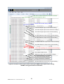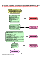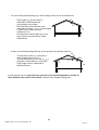
1
3 of 3
An Interface for SBEM (Simplified
Building Energy Model)
Part of the National Calculation Methodology : SBEM for assessing
the Energy Performance of Buildings
A User Guide to iSBEM:
(3) EPC Generation - UK
iSBEM version 5.2.d
31 July 2014
1
iSBEM version 5.2.d – EPC Generation - UK
31Jul14
Version history
User guide version
nd
For iSBEM version
Building Regulations
22 December 2005
1.0
24th January 2006
1.0.b
2006
2006
9 March 2006
1.0.b
2006
11th May 2006
1.1.a
2006
4th October 2006
1.2.a
2006
6th April 2007
2.0.a
2006
30th April 2007
2.0.b
2006
18th May 2007
2.0.c
2006
2nd November 2007
2.9.b
2006
6th February 2008
3.0.a
2006
12th February 2008
3.0.b
2006
1st April 2008
3.1.a
2006
9th July 2008
3.2.b
2006
10th November 2008
3.3.a
2006
23rd December 2008
3.3.b
2006
29th April 2009
3.4.a
2006
15th May 2009
3.4.a
2006
26th May 2009
3.4.a
2006
1st March 2010
3.5.a
2006
28th May 2010
4.0.a
2010
9 July 2010
4.0.a
2010
12th November 2010
4.1.a
2010
31 March 2011
4.1.c
2010
12th December 2011
4.1.d
2010
28 January 2013
4.1.e
2010
6th April 2014
5.2.b
2013 for England
th
th
st
th
st
1 July 2014
st
31 July 2014
5.2.d_beta
Beta 2014 for Wales
5.2.d
2013 for England and
2014 for Wales
Key changes and additions from previous versions of the User Guide
Changes and additions in 31 st July 2014 version 5.2.d:
There have been no changes since the previous version. Please see the other volumes in this
set: “How to use iSBEM: Basics - UK” and “How to use iSBEM: Compliance Assessment UK”.
2
iSBEM version 5.2.d – EPC Generation - UK
31Jul14
This manual, together with the software tools described in it, were developed by the BRE for the Department for Communities
and Local Government (DCLG).
Disclaimer
The iSBEM User Guide cannot provide legal advice or a definitive interpretation of the law. The
guidance provided in this document is limited to the technical operation of the software tool. It is
offered in good faith but is not binding on any person(s) or organization. The same applies to the
default values in the interface, which should be viewed as conservative suggestions intended to be
replaced by actual values.
3
iSBEM version 5.2.d – EPC Generation - UK
31Jul14
Table of Contents
Version history............................................................................................................................ 2
1.
WHAT IS IN THIS GUIDE .................................................................................. 8
1.1.
2.
CALCULATION BASICS ................................................................................... 9
2.1.
3.
Scope of the guide ...................................................................................... 8
UK Energy Performance Certificate purposes ............................................. 9
ENTERING A BUILDING INTO iSBEM............................................................ 12
3.1.
Important note on the default values in iSBEM .......................................... 12
3.2.
General form ............................................................................................. 12
3.2.1.
3.2.2.
3.2.3.
File Options tab........................................................................................................ 12
General Information tab ............................................................................................ 14
Obtaining Potential Asset Rating for EPC Scotland ................................................... 20
3.3.
Project Database form ............................................................................... 23
3.4.
Geometry form .......................................................................................... 24
3.4.1.
3.4.2.
3.4.3.
3.4.4.
3.4.5.
3.4.6.
3.5.
Project tab ............................................................................................................... 24
Defining zones – Zones tab ...................................................................................... 25
Defining envelopes – Envelope tab ........................................................................... 28
Defining windows and rooflights – Windows & Rooflights tab ..................................... 28
Defining doors – Doors tab ....................................................................................... 29
Quick Envelopes tab: Short cut to creating envelopes and windows ........................... 29
Building Services form ............................................................................... 29
3.5.1.
3.5.2.
3.5.3.
3.5.4.
3.5.5.
3.5.6.
3.5.7.
3.5.8.
3.5.9.
Global and Defaults tab ............................................................................................ 30
Defining HVAC Systems – HVAC Systems tab.......................................................... 32
Defining HWS – HWS tab ......................................................................................... 35
Defining Solar Energy Systems (SES) – SES tab ...................................................... 37
Defining a Photovoltaic system (PVS) – PVS tab....................................................... 37
Defining a wind generator – Wind Generators tab...................................................... 37
Defining a CHP generator – CHP Generator tab........................................................ 37
Defining a Solar Collector – Solar Collectors tab ....................................................... 37
Defining the zone specific building services- Zones tab ............................................. 37
3.6.
Building Navigation form............................................................................ 41
3.7.
About iSBEM form ..................................................................................... 41
4. CALCULATING AND VIEWING THE ENERGY PERFORMANCE OF THE BUILDING
- THE RATINGS FORM AND OUTPUT REPORTS ................................................ 42
4.1.
The Ratings form ....................................................................................... 42
4.1.1.
4.2.
Asset Rating tab....................................................................................................... 42
SBEM Output reports ................................................................................ 53
4.2.1.
4.2.2.
4.2.3.
4.2.4.
4.2.5.
4.2.6.
4.2.7.
4.2.8.
4.2.9.
4.2.10.
SBEM Main Output Document .................................................................................. 54
Data Reflection Report – Actual Building ................................................................... 54
Data Reflection Report – Notional Building ................................................................ 54
Technical Output Report – Actual Building ................................................................ 54
Technical Output Report – Notional Building ............................................................. 54
Energy Performance Certificate ................................................................................ 54
Recommendations Report ........................................................................................ 55
Technical Output Report – Reference Building .......................................................... 56
SBEM Secondary Recommendations Report ............................................................ 56
Accessing the reports from the project folder ............................................................. 57
4
iSBEM version 5.2.d – EPC Generation - UK
31Jul14
APPENDIX A:
A.1.
A.2.
A.3.
A.4.
Sample Output Reports ............................................................ 60
Sample Energy Performance Certificate.................................................................... 60
Recommendations Report for Example Building ........................................................ 62
Sample SBEM Secondary Recommendations Report................................................ 69
Sample Energy Performance Certificate for Scotland ................................................ 73
APPENDIX B:
List of parameters required by iSBEM for EPC calculations.. 74
APPENDIX C:
Connection to the National Register ........................................ 84
APPENDIX D:
Agreed convention for decision on assessment level............ 85
APPENDIX E:
Agreed convention for determining dimensions .................... 88
5
iSBEM version 5.2.d – EPC Generation - UK
31Jul14
List of Figures
Figure 1: The Local Area Network (LAN) Settings sub-tab ............................................................................ 13
Figure 2: The General Information tab in the General form .......................................................................... 14
Figure 3: The Additional project details sub-tab of the General Information tab in the General form ............. 16
Figure 4: The Building Details sub-tab of the General Information tab in the General form ........................... 17
Figure 5: The Energy Assessor Details in the General form........................................................................... 18
Figure 6: Insurance Details in the General form ........................................................................................... 20
Figure 7: Type of EPC for Scotland EPC for actual and potential buildings .................................................. 21
Figure 8: General form > Potential Measures tab ......................................................................................... 22
Figure 9: New scenario................................................................................................................................. 22
Figure 10: New improvement measure .......................................................................................................... 23
Figure 11: General & Geometry sub-tab of Project tab in the Geometry form................................................ 25
Figure 12: A zone being defined in the General sub-tab of the Zones tab in the Geometry form ...................... 27
Figure 13: The tabs in the Building Services form ......................................................................................... 30
Figure 14: Air Conditioning Inspection sub-tab of the Global and Defaults tab in the Building Services form 32
Figure 15: HVAC systems definition, Heating sub-tab ................................................................................... 34
Figure 16: HVAC systems definition: System Controls sub-tab ...................................................................... 35
Figure 17: Defining a HWS in the General sub-tab ....................................................................................... 36
Figure 18: Selecting a zone’s HVAC, HWS, and lighting systems ................................................................... 39
Figure 19: Defining the zone ventilation in the Ventilation sub-tab ................................................................ 40
Figure 20: Using the interface to calculate the Asset Rating for the building in the Asset Rating tab of the
Ratings form for England .............................................................................................................................. 44
Figure 21: Using the interface to calculate the Asset Rating for the building in the Asset Rating tab of the
Ratings form for Scotland ............................................................................................................................. 45
Figure 22: The Graphic Rating sub-tab in the Asset Rating tab of the Ratings form ....................................... 46
Figure 23: The Recommendations sub-tab in the Asset Rating tab of the Ratings form showing an NCM
recommendation ........................................................................................................................................... 49
Figure 24: The Recommendations sub-tab in the Asset Rating tab of the Ratings form showing the active fields
for creating a user-defined recommendation.................................................................................................. 50
Figure 25: The EPC Audit sub-tab in the Asset Rating tab of the Ratings form ............................................... 51
Figure 26: The Calculation Logs sub-tab in the Asset Rating tab of the Ratings form ..................................... 52
Figure 27: The Calculation Errors sub-tab in the Asset Rating tab of the Ratings form .................................. 53
Figure 28: Contents of the Projects folder showing the SBEM output reports when running SBEM for Energy
Performance Certificates .............................................................................................................................. 59
List of Tables
Table 1: Asset rating and energy bands in England, Wales, and Northern Ireland.......................................... 10
6
iSBEM version 5.2.d – EPC Generation - UK
31Jul14
Acronyms used in iSBEM and this guide
AHU
BER
BRUKL
CCHP
CEN
CHP
CO2
ECA
EER
EPBD
EPCgen
ETL
HEPA
HTHW
HVAC
HWS
IF
iSBEM
LTHW
LZC
MTHW
NCM
PVS
SBEM
SSEER
SSEff
SES
SFP
TER
VAV
VRF
Air Handling Unit
Building Emission Rate
Building Regulations United Kingdom Part L (The Building Regulations
compliance checking module)
Combined Cooling, Heat, and Power
Comité Européen de Normalisation (The European Committee for
Standardisation)
Combined Heat and Power
Carbon dioxide
Enhanced Capital Allowance
Energy Efficiency Ratio
Energy Performance of Buildings Directive
Energy Performance Certificate Generator (The EPC generator module)
Energy Technology List
High Efficiency Particulate Air
High Temperature Hot Water (boiler)
Heating Ventilation and Air Conditioning
Hot Water System
Improvement Factor
Interface for SBEM
Low Temperature Hot Water (boiler)
Low or Zero Carbon
Medium Temperature Hot Water (boiler)
National Calculation Methodology
Photovoltaic System
Simplified Building Energy Model
Seasonal System Energy Efficiency Ratio
Seasonal System Efficiency
Solar Energy System
Specific Fan Power
Target Emission Rate
Variable Air Volume
Variable Refrigeration Flow
7
iSBEM version 5.2.d – EPC Generation - UK
31Jul14
1. WHAT IS IN THIS GUIDE
1.1.
Scope of the guide
The objective of this this document is to give step-by- step-by-step guidance on the use of
iSBEM for the purpose of generating energy performance certificates for non-domestic buildings
in the UK.
This guide includes:
• How to work through the steps of the input procedure that are specific to EPC
calculations or different to those for compliance assessments, which are described in the
User Guide volume “How to use iSBEM: Compliance Assessment - UK”.
•
How to obtain the Energy Performance Certificate and Recommendations Report.
This guide does not include:
•
•
•
•
•
•
•
A detailed description of the structure of the NCM.
A full definition of the reference building which is used to produce the rating required by
the Energy Performance of Buildings Directive (EPBD), or the notional and typical
buildings.
The above can be found in England’s NCM Modelling Guide which is available from the
NCM website at www.ncm.bre.co.uk.
A description of the contents of the NCM Construction, Glazing, or Activity databases.
A detailed description of SBEM, the calculation engine to which iSBEM is an interface.
This is described in the SBEM Technical Manual, available for download from the NCM
website at www.ncm.bre.co.uk.
How to set up iSBEM to operate on your computer, how to assemble the required
information for your own building, how to zone your building, or how to convert files
created with previous versions of iSBEM version to be compatible with the current
version. This can be found in the User Guide volume “How to use iSBEM: Basics UK”.
A tutorial. This can be found in the User Guide volume “How to use iSBEM:
Compliance Assessment - UK”.
Guidance related to energy calculations for the Republic of Ireland Building Regulations
or those for the States of Jersey.
This manual is one volume in a set of documentations for the iSBEM User Guide. The other
volumes in this set are as follows:
•
How to use iSBEM: (1) Basics – UK – Contains an introduction to the use of iSBEM,
an interface for SBEM (Simplified Building Energy Model) - an approach for the National
Calculation Methodology (NCM) for assessing the energy performance of buildings.
•
How to use iSBEM: (2) Compliance Assessment – UK - Contains step-by-step
guidance on the use of iSBEM for the purpose of assessing compliance with the building
regulations in the UK for non-domestic buildings.
8
iSBEM version 5.2.d – EPC Generation - UK
31Jul14
2. CALCULATION BASICS
2.1.
UK Energy Performance Certificate purposes
The calculation procedure required by the NCM is explained more fully in the National
Calculation Methodology Modelling Guide. SBEM complies with the NCM. It is suitable for use
with the majority of buildings, but some designs will contain features that mean that more
accurate energy calculations may be obtained by more sophisticated calculation methods.
This section briefly defines the “reference” building, which is the basis of setting the energy
rating scale for Energy Performance Certificates (EPCs) for England, Wales, and Northern
Ireland. The “Asset Rating” rates the CO2 emissions from the actual building in comparison to a
Standard Emission Rate (SER), where both emission values are in kgCO2/m2.annum. The
Standard Emission Rate is determined by applying a fixed improvement factor to the emissions
from a reference building, which is defined below.
EPCs are intended to send market signals about the relative performance of comparable
buildings, and so it is necessary that the reference building should be the same for all buildings
of a given type. In order to provide this consistency, the reference building must be the same
irrespective of: (a) whether the actual building is naturally ventilated or air conditioned and (b)
the fuel choice in the actual building.
The insulation levels and HVAC efficiencies in the reference building are identical to the 2006
Part L notional building except that certain parameters in the reference building are fixed
(subject to conditions below) irrespective of features in the actual building (please refer to the
2013 NCM Modelling Guide, available from www.ncm.bre.co.uk, for the detailed description of
the reference building). These aspects are:
a. The heating and hot water service is always met by a gas-fired system irrespective of
whether a fuel other than gas is used in the actual building, or is even available in the
locality of the actual building.
b. The spaces in the reference building have a fixed servicing strategy regardless of the
strategy adopted in the actual building (except if the corresponding space in the actual
building is unconditioned – see below). Therefore:
•
Each space is heated to the heating setpoints defined in the activity database,
irrespective of whether the particular space in the actual building has heating
provision or not (except if the corresponding space in the actual building is totally
unconditioned – see below).
•
Each space is cooled, to a fixed cooling setpoint, irrespective of whether the
particular space in the actual building has cooling provision or not (except if the
corresponding space in the actual building is totally unconditioned – see below).
•
Each space which is unconditioned, i.e., unheated and uncooled, in the actual
building will also be unconditioned in the reference building.
•
Each space is naturally ventilated, irrespective of whether the corresponding space
in the actual building has natural or mechanical ventilation.
The CO2 emissions arising from the use of the fixed building services in the reference building
(in kgCO2/m2.annum) are calculated (the Reference Emission Rate or RER), and then adjusted
by an improvement factor of 23.5%. This adjusted CO2 emission rate (in kgCO2/m2.annum) is
termed the Standard Emission Rate (SER), i.e., SER = RER*0.765.
It is not intended that the definition of the reference building should change as Part L standards
change, since this would mean that the energy rating of a given building would also change,
even if its energy efficiency had not been varied. Therefore, the reference building is always as
9
iSBEM version 5.2.d – EPC Generation - UK
31Jul14
defined above (please refer to the 2013 NCM Modelling Guide, available from
www.ncm.bre.co.uk, for the detailed description of the reference building).
The Asset Rating (AR) in England, Wales, and Northern Ireland is simply the ratio of the CO2
emissions from the actual building (i.e., the BER) to the Standard Emission Rate (i.e., the SER)
multiplied by 50. The AR should be rounded to the nearest whole number.
BER
∗ 50 = AR
SER
The Asset Rating is also converted into an energy band/grade on a linear “A-G” scale (with A+
being the most efficient followed by A, and G being the least efficient), Table 1, where the border
between grade B and grade C is set at the SER and given an AR of 50. This means that a gasheated building with mixed-mode cooling that is just compliant with Part L 2006 would have an
Asset Rating of 50.
Table 1: Asset rating and energy bands in England, Wales, and Northern Ireland
More details on the calculation procedure required by the NCM and the definition of the rating
scale are explained in more detail in the NCM Modelling Guide (available from
www.ncm.bre.co.uk).
Further information on EPCs (including the treatment of communal areas that accompany units
with independent heating systems) can be found in DCLG’s publication: I“mproving the energy
efficiency of our buildings: A guide to energy performance certificates for the construction, sale
and let of non-dwellings” which can be accessed from
https://www.gov.uk/government/publications/energy-performance-certificates-for-theconstruction-sale-and-let-of-non-dwellings--2. This document provides an introduction to energy
performance certificates for non-dwellings, describes the scope and requirements of the
regulations that apply on construction, sale, or let, and provides guidance on how these are
applied in practice.
NB: While no EPCs are required for permanently unconditioned buildings (i.e., buildings which
do not use energy to condition the indoor climate and are expected to remain this way), it is
possible to voluntarily lodge EPCs for unconditioned buildings and, as such, the definition of the
reference building was revised (see above) in order to allow for the calculated energy rating for
10
iSBEM version 5.2.d – EPC Generation - UK
31Jul14
these types of buildings to be representative. Permanently unconditioned buildings are different
to those which are expected to be conditioned later on, and which should be modelled as per
the guidance in DCLG’s publication: “Improving the energy efficiency of our buildings: A guide to
energy performance certificates for the construction, sale, and let of non-dwellings” which can
be accessed as above. Buildings with no building services currently installed, but which are
expected to be installed in the future, should be modelled in iSBEM for the purposes of
producing an EPC with assumed building services of the types that are most likely to be
installed in those class of buildings and which have the minimum acceptable specification
standards that meet the requirements in Part L of the Building Regulations in force when the
building was constructed.
NB: The domestic type activities available under the building type “Residential spaces” in
iSBEM are to allow the energy calculations for the generation of one EPC for a building which
contains residential accommodation above a non-domestic space (e.g., a shop or a pub)
provided that the residential space can only be accessed from within the non-domestic space,
i.e., the residential part is not designed or altered for use as a separate independent dwelling. In
addition to common circulation areas of apartment buildings containing self-contained flats,
these are the only cases where SBEM can be used to model domestic areas. For more
information on the appropriate software tools to use for modelling your building, please refer to
DCLG’s publication: “Improving the energy efficiency of our buildings: A guide to energy
performance certificates for the construction, sale, and let of non-dwellings” which can be
accessed as above.
In Scotland, the EPC displays the approximate CO2 emissions and energy usage of the building
based on a standardised use of the building. The Rating is expressed as the CO2 emissions in
kg per m2 of floor area per year (i.e., the same as BER), and it determines where the building
sits on a seven band scale. The EPC also includes a list of recommendations for the costeffective improvements (lower cost measures) of the energy performance. Further information is
available from the Building Standards Division at http://www.scotland.gov.uk/Topics/BuiltEnvironment/Building/Building-standards.
For Northern Ireland, the EPC is very similar to that in England and Wales. Please refer to
www.dfpni.gov.uk for further information on building regulations.
11
iSBEM version 5.2.d – EPC Generation - UK
31Jul14
3. ENTERING A BUILDING INTO iSBEM
This chapter takes you through each of the iSBEM data entry forms consecutively (theGeneral,
Project Database, Geometry, and Building Services forms), giving guidance on what information
is required at each stage, wherever it is different to, or in addition to, that required for
compliance assessments as described in the in the User Guide volume “How to use iSBEM:
Compliance Assessment - UK”.
3.1.
Important note on the default values in iSBEM
In iSBEM, there are default values included for various parameters. For example, there are
default seasonal efficiencies for HVAC systems and default constructions for envelope elements
so that you can select them when defining the envelopes of a zone when learning how to use
the tool. These default values are not generous (i.e., usually pessimistic), should be checked by
the user, and, if appropriate, changed or added to.
NB: If none of the default values in iSBEM are changed when modelling a new building, it
is likely that the building will achieve a poor asset rating.
3.2.
General form
The General form contains two tabs:
•
File Options tab
•
General Information tab
3.2.1. File Options tab
The File Options tab has five sub-tabs:
• File Operations sub-tab.
• System Configuration sub-tab.
• System Configuration (cont.) sub-tab.
• Local Area Network (LAN) Settings sub-tab.
• Helpline Diagnosis sub-tab.
File Operations sub-tab:
Guidance on input in this sub-tab is the same as that provided in the User Guide volume How
“
to use iSBEM: Compliance Assessment - UK”.
System Configuration sub-tab:
Guidance on input in this sub-tab is the same as that provided in the User Guide volume How
“
to use iSBEM: Compliance Assessment - UK”.
System Configuration (cont.) sub-tab:
Guidance on input in this sub-tab is the same as that provided in the User Guide volume How
“
to use iSBEM: Compliance Assessment - UK”.
12
iSBEM version 5.2.d – EPC Generation - UK
31Jul14
Local Area Network (LAN) Settings sub-tab:
In this sub-tab, the following information can be entered (Figure 1):
Proxy Server
1. Tick box to indicate whether a proxy server is used (by a Local Area Network) for connecting
your computer to the Internet. If the box is ticked, i.e., a proxy server is used, then the
following fields become active:
a. Address - the URL address of the proxy server used.
b. Port - the port of the proxy server used.
c. Tick box to indicate whether the proxy server requires a password. If the box is
ticked, then the following field becomes active:
i. User name – the user name for the proxy server.
ii. Password – the password for the proxy server.
NB: All information on the proxy server, if one is used, should be available from your IT
Department.
NB: Please note that in order to generate the XML message for official lodgement in England,
Wales, and Northern Ireland, your computer must be connected to the internet, and you need to
enter your assessor number into the General form > General Information tab > Energy Assessor
Details sub-tab > Energy Assessor Details sub-form (see Section 3.2.2: General Information
tab). If there is no internet connection, then the XML message will not be generated. Please
note that the EPC and Recommendations Report produced on your computer will always
contain the watermark. However, this does not apply if ‘EPC Scotland’ has been selected as the
“Purpose of Analysis”, when the XML is always generated if the calculation runs successfully,
and the EPC documents generated on your computer are not watermarked.
NB: See APPENDIX C: Connection to the National Register, for more guidance and troubleshooting steps.
Figure 1: The Local Area Network (LAN) Settings sub-tab
13
iSBEM version 5.2.d – EPC Generation - UK
31Jul14
Helpline Diagnosis sub-tab:
Guidance on input in this sub-tab is the same as that provided in the User Guide volume“How
to use iSBEM: Compliance Assessment - UK”.
3.2.2. General Information tab
The General Information tab contains a few sub-tabs, as described below, where you can enter
as much or as little background information about the project. However, there are also essential
parameters to be selected, such as the weather location for the project and the purpose of the
analysis. These details can be entered and edited in their respective tabs (seeFigure 2). Some
of this information may have already been entered when the project was first created (see the
User Guide volume “How to use iSBEM: Basics - UK”).
The General Information tab contains the following sub-tabs:
• Project Details sub-tab.
• Additional Project Details sub-tab.
• Special Considerations sub-tab.
• EPBD Recast sub-tab.
• Building Details sub-tab.
• Certifier Details OR Energy Assessor Details OR Agent Details OR
Qualified/Accredited Person sub-tab.
• Owner Details sub-tab.
Figure 2: The General Information tab in the General form
14
iSBEM version 5.2.d – EPC Generation - UK
31Jul14
Project Details sub-tab:
Guidance on input parameters in this sub-tab not described below is the same as that provided
in the User Guide volume “How to use iSBEM: Compliance Assessment - UK”.
In this sub-tab, the following information can be entered (Figure 2):
Building Regulations & EPBD Parameters
1. Purpose of the analysis – purpose for carrying out a calculation using SBEM, whether it is to
generate an Energy Performance Certificate in England or any other country in the UK, e.g.,
EPC England.
2. Type of EPC – whether the model created is for the Actual building (building as currently is)
or the Potential building (building with potential improvements). This parameter is active only
if the “Purpose of Analysis” parameter is set to ‘EPC Scotland’ in order to enable the
assessor to create a scenario (similar to the process applied in the Green Deal Tool) which
features the selected improvements so that the tool can calculate the potential asset rating
which appears on the Scotland EPC.
NB: If the Energy Assessor wants the potential asset rating to be populated on the Scotland
EPC and its XML file, a scenario for the potential building with the recommended improvements
needs to be created and run successfully as described in Section 3.2.3: Obtaining Potential
Asset Rating for EPC Scotland.
NB: SBEM now automatically calculates the comparative England asset rating and reports it on
the XML file for Scotland EPC.
3. Tick box to indicate whether you wish to produce the EPC in Welsh as well as in English –
This parameter is active only if the “Purpose of Analysis” parameter is set to ‘EPC Wales’.
4. Tick box to indicate whether, in addition to producing an EPC, you wish to check compliance
with Building Regulations and produce a compliance document.
5. Stage of analysis – Only the option “as built” is available when the purpose of analysis is
generating an EPC.
6. Project complexity – complexity of the building for the purposes of energy assessments for
EPCs. The options available are:
•
‘Level 3’ – simple, existing buildings that can be modelled using SBEM, e.g., small
buildings such as converted houses or doctors’ surgeries.
•
‘Level 4’ – new and existing buildings that can be modelled using SBEM, e.g., small
purpose built office buildings.
•
‘Level 5’ – new and existing complex buildings that need to be modelled using
Dynamic Simulation Models (DSMs), e.g., large office buildings or factories.
The decision of which level of assessor should be assigned to a particular building
should follow the agreed convention flow chart in APPENDIX D:.
NB: If in doubt about whether iSBEM would be appropriate for modelling your building,
please contact your Accreditation Scheme Provider.
7. Main renewable source – Select to either let SBEM determine the main renewable source to
appear on the Scottish EPC based on the input parameters and the calculated results
(select “From calculation”), or to display ‘Other non-calculated’ on the EPC to denote that
the main renewable source is of a type that cannot currently be modelled in SBEM . This
parameter is active only if the Scottish EPC is selected in the “Purpose of the Analysis”
parameter above.
15
iSBEM version 5.2.d – EPC Generation - UK
31Jul14
Figure 3: The Additional project details sub-tab of the General Information tab in the General
form
Additional Project Details sub-tab:
In this sub-tab, the following information can be entered (Figure 3):
1. Related party disclosure – any related party disclosure by the Energy Assessor for the
purposes of energy calculations for EPCs. This parameter is active only if the “Purpose of
Analysis” parameter is set to ‘EPC England’, ‘EPC Wales’, or ‘EPC Northern Ireland’.NB: A
valid option for this parameter must be selected for the EPC calculation to run successfully.
2. Transaction type – the transaction type which has prompted the generation of the EPC. A
valid option for this parameter must be selected from the drop-down menu for the EPC
calculation to run successfully.
16
iSBEM version 5.2.d – EPC Generation - UK
31Jul14
Figure 4: The Building Details sub-tab of the General Information tab in the General form
Building Details sub-tab:
Guidance on input parameters in this sub-tab not described below is the same as that provided
in the User Guide volume “How to use iSBEM: Compliance Assessment - UK”.
In this sub-tab (Figure 4), the following information can be entered:
Building Details
1. UPRN - the Unique Property Reference Number (UPRN) of the building. In England, Wales,
and Northern Ireland, this parameter consists of 12 digits while in Scotland, it consists of 10
digits. It should not be left blank.
2. Access restriction - Specifies if any restrictions are to be imposed on the retrieval of the
EPC’s XML file from the National Register in Scotland. This parameter is active only if the
Scottish EPC is selected in the “Purpose of the Analysis” parameter.
3. Inspection Date – the date on which the energy assessor inspected the building for the
purposes of energy calculations for EPCs.
4. Tick box to indicate whether the building has a special conservation status (i.e., the building
has been identified as being: one of special architectural or historical interest, in a
conservation area, in a designated area of special character or appearance, or of traditional
construction) - This parameter is active only if the “Purpose of Analysis” parameter is set to
‘EPC England’, ‘EPC Wales’, or ‘EPC Northern Ireland’.
Energy Assessor Details / Qualified/Accredited Person Details sub-tab:
The name of this sub-tab changes depending on the option selected in the parameter “Purpose
of Analysis” in the Projects Details sub-tab, as follows:
• Energy Assessor Details sub-tab – if the option selected is ‘EPC England’, ‘EPC
Wales’, or ‘EPC Northern Ireland’.
• Qualified/Accredited Person Details sub-tab – if the option selected is ‘EPC Scotland’.
17
iSBEM version 5.2.d – EPC Generation - UK
31Jul14
This sub-tab (Figure 5) contains two sub-forms: Energy Assessor Details sub-form and
Insurance Details sub-form.
Figure 5: The Energy Assessor Details in the General form
Energy Assessor Details sub-form: in this sub-form, the following information can be entered:
1. Name – of the energy assessor or qualified/accredited person.NB: The input should be as
you want it to appear in the XML file and lodged EPC.
2. Address – of the energy assessor or qualified/accredited person.NB: The input should be
as you want it to appear in the XML file and lodged EPC.
3. City – of the energy assessor or qualified/accredited person.NB: The input should be as
you want it to appear in the XML file and lodged EPC.
4. Post Code – of the energy assessor or qualified/accredited person.NB: The input should be
as you want it to appear in the XML file and lodged EPC.
5. Telephone number – of the energy assessor or qualified/accredited person.
6. Email address – of the energy assessor or qualified/accredited person.
7. Accreditation Scheme – the name of the Accreditation Scheme to which the energy
assessor belongs. For energy assessors accredited with more than one scheme, the
scheme name you input here should correspond to the Assessor Number you input below.
8. Assessor number – the registration number of the energy assessor within his Accreditation
Scheme. This parameter must consist of 4 letters followed by 6 digits, and it should not be
left blank. For energy assessors accredited with more than one scheme, the assessor
number you input here should correspond to the name of the Accreditation Scheme you
input above. NB: The input should be exactly as on the National Register of non-domestic
Energy Assessors (www.ndepcregister.com for England & Wales and
www.epbniregisternd.com for Northern Ireland). If in doubt, please contact your
Accreditation Scheme Provider.
18
iSBEM version 5.2.d – EPC Generation - UK
31Jul14
9. Qualifications – the qualifications of the energy assessor as they will need to be qualified for
the type of building being assessed (check with your Accreditation Scheme Provider). This
parameter is active only if the “Purpose of Analysis” parameter is set to ‘EPC England’, ‘EPC
Wales’, or ‘EPC Northern Ireland’. See the “Project complexity” parameter in theGeneral
Information tab.
10. Emp/Trading Name – the employer or the trading name of the energy assessor. This
parameter is active only if the “Purpose of Analysis” parameter is set to ‘EPC England’, ‘EPC
Wales’, or ‘EPC Northern Ireland’. NB: The input should be exactly as you want it to appear
in the XML file and lodged EPC.
11. Emp/Trading Address – the employer or the trading address of the energy assessor. This
parameter is active only if the “Purpose of Analysis” parameter is set to ‘EPC England’, ‘EPC
Wales’, or ‘EPC Northern Ireland’. NB: The input should be exactly as you want it to appear
in the XML file and lodged EPC.
NB: See APPENDIX C: Connection to the National Register, for more guidance and troubleshooting steps.
NB: Please note that in order to generate the XML message for official lodgement in England,
Wales, and Northern Ireland, your computer must be connected to the internet, and you should
enter your assessor number into the General form > General Information tab > Energy Assessor
Details sub-tab > Energy Assessor Details sub-form (see Section 3.2.2: General Information
tab). If there is no internet connection, then the XML message will not be generated. Please
note that the EPC and Recommendations Report produced on your computer will always
contain the watermark. However, this does not apply if ‘EPC Scotland’ has been selected as the
“Purpose of Analysis”, when the XML is always generated if the calculation runs successfully,
and the EPC documents generated on your computer are not watermarked
IMPORTANT: Energy Assessors should now input their full details (name, address,
qualifications, name of Accreditation Scheme Provider, trading name, etc.) in the interface
exactly as they want them to appear in the XML file and on the lodged EPC, as well as their
assessor number. This is because the new verification system will not overwrite these details
with information from the National Register.
12. Membership Number – the membership number of the qualified/accredited person. This
parameter is active only if the “Purpose of Analysis” parameter is set to ‘EPC Scotland’.
13. Protocol Organisation – the accreditation scheme of the qualified/accredited person. This
parameter is active only if the “Purpose of Analysis” parameter is set to ‘EPC Scotland’.
Import Details – clicking on either of the two buttons available will enable you to import the
assessor details which you might have entered in a previous version of iSBEM, instead of retyping them. After you click on the button, you will have the option to browse the folders on your
computer and select a previous version of iSBEM, for e.g., iSBEM_v4.1.e.mdb, from which to
import the previously input details into the version of iSBEM you are working with.
If you are importing details from a version of iSBEM specifically for MS Office 2003, use the
“Import details from mdb” button to import your details from an “.mdb” file. If you are importing
details from a version of iSBEM specifically for MS Office 2007, use the “Import details from
accdb” button to import your details from an “.accdb” file.
NB: If you are running the Office 2007 version of iSBEM, you can import assessor details from
an Office 2003 or an Office 2007 version of iSBEM, i.e., 2 buttons will be visible in the interface
for “mdb” and “accdb” files, respectively. On the other hand, if you are running the Office 2003
version of iSBEM, you can import details from a previous Office 2003 version of iSBEM only,
i.e., only 1 button for “mdb” files will be visible in the interface.
Clear all – All the information in the Energy Assessor Details / Qualified/Accredited Person
Details sub-tab will remain visible in any new project created but can be cleared by pressing the
“Clear all” button.
19
iSBEM version 5.2.d – EPC Generation - UK
31Jul14
Figure 6: Insurance Details in the General form
Insurance Details sub-form: This is where the following information can be entered:
1. Insurer Company – Name of the energy assessor’s insurance company.NB: The text input
in this field should not include any double quotes.
2. Policy Number – The energy assessor’s insurance policy number.
3. Effective Date – The energy assessor’s insurance policy effective start date.
4. Expiry Date – The energy assessor’s insurance policy expiry date.
5. PI Limit – The energy assessor’s insurance policy cover limit.
Owner Details sub-tab:
Guidance on input in this sub-tab is the same as that provided in the User Guide volume How
“
to use iSBEM: Compliance Assessment - UK”.
3.2.3. Obtaining Potential Asset Rating for EPC Scotland
In order to obtain the potential asset rating for a Scotland EPC, the assessor will need to have
first run the EPC calculation to obtain the asset rating for the building as it currently is, i.e., with
the EPC Type parameter in the General form > General Information tab > Project details sub-tab
set to “Actual” (see Figure 7).
20
iSBEM version 5.2.d – EPC Generation - UK
31Jul14
Actual = EPC for
building as currently is
Potential = EPC for
building with selected
recommended
improvements
Figure 7: Type of EPC for Scotland EPC for actual and potential buildings
In order to generate the potential asset rating with the recommended improvements, this will
necessitate creating a scenario in iSBEM and then implementing the selected improvements to
the building model. The format of the software tool in this mode is very similar to that used for
Green Deal assessments in the GDTool (www.ncm-sbem.org.uk) so should be familiar to
assessors who have undergone Green Deal training.
To create a scenario of recommended improvements in iSBEM:
1. Set the “Type of EPC” parameter to “Potential” in the General form > General Information
tab > Project details sub-tab (see Figure 7). This action causes a new tab entitledPotential
Measures to appear in the General form (see Figure 8).
2. From the “Record selector” drop-down menu in the Potential Measures tab, select the option
“Create new Scenario based on BASELINE”. This will create a copy of the baseline building
model, i.e., the building as-is, on which the assessor can make alterations to add
improvement measures while leaving the original baseline model unaffected.
3. The ‘Scenario copy’ is assigned the name “New Scenario” by default, but the name can be
changed by editing the text within the “Name” field (see Figure 9). A short description may
also be entered in the “Description” field explaining what changes will be introduced and
assessed, but this is not obligatory. Notice that the name of the scenario the user is working
on is shown at the top left hand side of theGeneral form in green text for reference.
4. To create an improvement measure, in the General form > Potential Measures tab >
Improvements sub-tab, input a name for the improvement measure within the “New
Measure” field, and click on the Create button. Notice that the name of the measure will
appear at the top of the form in green text for reference. A short description of the measure
may also be entered in the “Description” field, such as what change it entails (see Figure
10).
21
iSBEM version 5.2.d – EPC Generation - UK
31Jul14
Figure 8: General form > Potential Measures tab
Figure 9: New scenario
22
iSBEM version 5.2.d – EPC Generation - UK
31Jul14
Figure 10: New improvement measure
5. At this point, the assessor should go to the relevant section in iSBEM in order to make the
change to the building model that is relevant to the improvement measure just created. For
example, if the measure is for changing T8 lamps to T5 lamps, the assessor should go to
the Building Services form > Zones tab > Lighting sub-tab, and change the lamp types of all
the zones which have T8 to T5. If the recommended improvement is to upgrade singleglazed windows to double-glazing, the assessor should got to theProject Database form >
Glazing tab > General sub-tab and modify the definition of the glazing type which is
assigned to those windows. If the recommended improvement is for adding a PV system,
then the assessor should go to the Building Services form > PVS tab > General sub-tab, and
enter the definition of the PV system in order to add it to the building model, and so on.
6. Once the building model has been modified with the recommended improvement measures,
the impact on the energy performance of the building and its CO2 emissions can be
assessed. In the Ratings form, click on the Calculate EPC rating button (see section 4.1.1:
Asset Rating tab) to initiate the calculation of the building’s performance with the
improvement scenario (containing all the recommended improvement measures in a single
package).
7. After the calculation has completed successfully, the potential asset rating for the building
with the recommended improvements will appear in the relevant section on the actual
building’s EPC which is generated on the user’s computer, and it will also be recorded on
the generated XML file so that it can appear on the official EPC generated at the Scottish
National Register after lodgement.
3.3.
Project Database form
Guidance on input in this form is the same as that provided in the User Guide volume H
“ ow to
use iSBEM: Compliance Assessment - UK”.
23
iSBEM version 5.2.d – EPC Generation - UK
31Jul14
3.4.
Geometry form
Guidance on input parameters in this form not described below is the same as that provided in
the User Guide volume “How to use iSBEM: Compliance Assessment - UK”.
3.4.1. Project tab
This tab consists of the following two sub-tabs:
•
General & Geometry sub-tab
•
Thermal Bridges sub-tab
General & Geometry sub-tab:
Guidance on input parameters in this sub-tab not described below is the same as that provided
in the User Guide volume “How to use iSBEM: Compliance Assessment - UK”.
This sub-tab requires the input of the following information, as shown in Figure 11:
Building Infiltration (Global)
1. Air permeability at 50 pa (m3/h.m2) - If the purpose of analysis option that has been
selected in the General form > General Information tab > Project Details sub-tab is EPC
generation, then iSBEM’s default value for air permeability will be 25 m3/h.m2. However,
the user can over-write the default value by manually entering an alternative value.
Convention: For EPCs - Air permeability
To accommodate different ages and types of building where the SBEM default value of 25 m3/h
m 2 for all existing buildings has been viewed as unduly restrictive, the value shall be amended
as follows:
- Less than 10 m3/h.m2 – only with an accredited air pressure test result
- 10 m3/hm2 – buildings with total floor area > 500 m2, built to 2002 Building Regulations
- 15 m3/hm2 – buildings with total floor area <= 500 m2, built to 2002 Building Regulations and
buildings built to 1995 Building Regulations
- 25 m3/hm2 – buildings built to Building Regulations pre 1995
- 35 m3/hm2 – to be considered where buildings are pre 1995 regulations and where suitable
evidence of high permeability exists, e.g., single skin metal-clad structure within “Planning Use
Class B2 – B8” with large roller shutter doors and poor constructional details, etc.
24
iSBEM version 5.2.d – EPC Generation - UK
31Jul14
Figure 11: General & Geometry sub-tab of Project tab in the Geometry form
Thermal bridges sub-tab:
Guidance on input in this sub-tab is the same as that provided in the User Guide volume How
“
to use iSBEM: Compliance Assessment - UK”.
3.4.2. Defining zones – Zones tab
Guidance on input parameters in this tab not described below is the same as that provided in
the User Guide volume “How to use iSBEM: Compliance Assessment - UK”.
NB: For building regulations calculations purposes, we recommend that users generally avoid
creating more than 100-150 zones in iSBEM. However, the processing time will depend on the
total number of objects (not just zones), i.e., zones, envelopes, windows, etc. Note that for the
asset rating to be calculated for an EPC, 3 buildings need to be generated: actual, notional, and
reference (typical is based on the notional building’s performance), i.e., all the objects in the
input are multiplied by 3 to give the total number of objects being processed by SBEM. Hence,
creating a project with a very large number of objects will slow down the calculation and may
cause it to crash.
The Zones tab contains four sub-tabs:
• General sub-tab.
• Quick Envelopes sub-tab.
• Thermal bridges sub-tab.
• Envelope Summary sub-tab.
25
iSBEM version 5.2.d – EPC Generation - UK
31Jul14
General sub-tab:
Guidance on input parameters in this sub-tab not described below is the same as that provided
in the User Guide volume “How to use iSBEM: Compliance Assessment - UK”.
To create a zone, you will need to click into the General sub-tab of the Zones tab, add a new
record, and enter the following information:
1. HVAC System – If you have defined your HVAC systems before defining your zones
(i.e., if you have started with the Building Services form instead of the Geometry form),
you can select the HVAC system that serves this zone from the drop-down list. If no
HVAC system serves the space (i.e., an unconditioned zone that is intended to remain
that way), select ‘Zones without HVAC system’ (spaces which have no heating or
cooling, e.g., plant rooms, storage spaces, exposed circulation spaces). If you have not
yet defined your HVAC system, this can be left as ‘Unassigned’ at this stage. You will be
able to assign the zones to an HVAC system later within theBuilding Services form so
there is no need to define the HVAC system before continuing. If you leave the zone as
unassigned, a red warning will appear in the top right hand corner to let you know how
many zones remain unassigned so that you would not proceed with running the
calculation before assigning them.
NB: If a zone is defined as having no heating or cooling, i.e., assigned to ‘Zones without
HVAC system’, but the activity type selected for the zone is one which typically requires
conditioning (according to the Activity Database), a red exclamation mark “!” will appear
next to this parameter as a warning to the user, in case this was done in error.
Ultimately, however, the calculation will be carried out using the data input by the user.
If you do not know the type of the HVAC system in your existing building or its detailed
parameters when modelling a building for an EPC calculation, you should select one of
the following default options from the drop-down menu (see Section 3.5: Building
Services form):
•
‘Heating only - Electric resistance’ - Heat generated by passing an electric current
through resistance wire. Assumed to be electric central heating system with warm air
distribution. Fan storage heaters and electric fan converters should be input by
defining an HVAC system in the Building Services form > HVAC Systems tab >
General sub-tab and selecting the system type "Other local room heater - fanned". If
you do not know the heating method (i.e., whether a heated-only building uses
electricity or a fuel-based heating system), you should select electric resistance
heating as your default.
•
‘Heating only - Other systems’ - Assumed to be a wet radiator system with heat
generated by fuel combustion. Pumps assumed to be powered by grid-supplied
electricity. If you know the fuel type used by the heating system, you can define it in
the Building Services form > Global and Defaults tab > HVAC System Defaults subtab (see Section 3.5.1: Global and Defaults tab).
•
‘Heating and mechanical cooling’ - Assumed to be a constant volume air system with
terminal reheat and fixed fresh air. Refrigeration (chillers), fans, and pumps
assumed to be powered by grid-supplied electricity. If you know the fuel type used
by the heating system, you can define it in theBuilding Services form > Global and
Defaults tab > HVAC System Defaults sub-tab (see Section 3.5.1: Global and
Defaults tab).
NB: The default HVAC systems in iSBEM are representative of existing rather than new
buildings and should only be used if you are running an EPC calculation for an existing building
(not a new building) and do not know the type of the HVAC system in your building or its
detailed parameters as the default efficiencies assumed by iSBEM for them are quite pessimistic
and cannot be edited by the user.
NB: The domestic type activities available under the building type “Residential spaces” in
iSBEM are to allow the energy calculations for the generation of one EPC for a building which
26
iSBEM version 5.2.d – EPC Generation - UK
31Jul14
contains residential accommodation above a non-domestic space (e.g., a shop or a pub)
provided that the residential space can only be accessed from within the non-domestic space,
i.e., the residential part is not designed or altered for use as a separate independent dwelling. In
addition to common circulation areas of apartment buildings containing self-contained flats,
these are the only cases where SBEM can be used to model domestic areas. For more
information on the appropriate software tools to use for modelling your building, please refer to
DCLG’s publication: “Improving the energy efficiency of our buildings: A guide to energy
performance certificates for the construction, sale, and let of non-dwellings” which can be
accessed from DCLG’s website at https://www.gov.uk/government/publications/energyperformance-certificates-for-the-construction-sale-and-let-of-non-dwellings--2.
Infiltration
2. Air permeability at 50pa, in m3/h.m2 - If the purpose of analysis option that has been
selected in the General form > General Information tab > Project Details sub-tab is EPC
generation, then iSBEM’s default value for air permeability will be 25 m3/h.m2. However,
the user can over-write the default value by manually entering an alternative value.NB:
For EPCs of existing buildings, note that the air permeability convention given in section
3.4.1: Project tab should apply.
Figure 12 shows a zone being defined.
Notes entered at the user’s
discretion about the zone.
A description of the selected
activity area as it appears in
the NCM Activity database.
Selected building
type for this
zone.
Selected activity
type for this
zone.
Figure 12: A zone being defined in the General sub-tab of the Zones tab in the Geometry form
Thermal Bridge sub-tab:
Guidance on input in this sub-tab is the same as that provided in the User Guide volume How
“
to use iSBEM: Compliance Assessment - UK”.
Envelope Summary sub-tab:
Guidance on this sub-tab is the same as that provided in the User Guide volume H
“ ow to use
iSBEM: Compliance Assessment - UK”.
27
iSBEM version 5.2.d – EPC Generation - UK
31Jul14
3.4.3. Defining envelopes – Envelope tab
Guidance on input parameters in this tab not described below is the same as that provided in
the User Guide volume “How to use iSBEM: Compliance Assessment - UK”.
The main Envelope tab contains two sub-tabs:
General sub-tab.
Window & Door Summary sub-tab.
General sub-tab:
Guidance on input parameters in this sub-tab not described below is the same as that provided
in the User Guide volume “How to use iSBEM: Compliance Assessment - UK”.
For each envelope element, you will need to click into theGeneral sub-tab of the Envelope tab,
create a new record, and add the following information:
1. Connects space to (sometimes referred to as “adjacent condition”) – Here you need to
select what conditions apply on the other side of the wall/floor or ceiling/roof.
Convention: For EPCs - Adjacent condition of adjoining buildings
Unless evidence to the contrary is readily and easily available, all buildings adjoining that
building or part-building which is being assessed, are assumed to be conditioned unless they
are of “Planning Class B2 to B8” in which case, they are assumed to be unconditioned. This
applies regardless of whether they are actually occupied or are inaccessible. This convention
only applies for the assessment of EPCs.
Convention: For EPCs - Boundary of assessed building when other buildings adjoin
Where there is a party wall between buildings, this is deemed (in compliance with the RICS
definition of internal areas) to be a perimeter wall, and therefore, horizontal dimensions
should be measured to the inside face from the side of the building being assessed.
NB: If surfaces of the room are not rectilinear, for example, if a pitched roof is exposed to
the inside of the conditioned zone (i.e., there is no flat ceiling underneath it), then the roof
area will be that of the inner surface area of the roof as "seen" by the heat flux.
Convention: For EPCs - Dimension conventions
See APPENDIX E: for the treatment of other rooms with non-rectilinear surfaces.
Windows & Doors Summary sub-tab:
Guidance on this sub-tab is the same as that provided in the User Guide volume H
“ ow to use
iSBEM: Compliance Assessment - UK”.
3.4.4. Defining windows and rooflights – Windows & Rooflights tab
Guidance on input in this tab is the same as that provided in the User Guide volume H
“ ow to
use iSBEM: Compliance Assessment - UK”.
28
iSBEM version 5.2.d – EPC Generation - UK
31Jul14
3.4.5. Defining doors – Doors tab
Guidance on input in this tab is the same as that provided in the User Guide volume H
“ ow to
use iSBEM: Compliance Assessment - UK”.
3.4.6. Quick Envelopes tab: Short cut to creating envelopes and
windows
Guidance on input in this sub-tab is the same as that provided in the User Guide volume How
“
to use iSBEM: Compliance Assessment - UK”.
3.5.
Building Services form
Guidance on input parameters in this form not described below is the same as that provided in
the User Guide volume “How to use iSBEM: Compliance Assessment - UK”.
This form holds all the information relating to the building services. This information is entered
into the following main tabs (these are circled in Figure 13):
• Global and Defaults tab – This tab contains some default information on HVAC
systems if no or little information is known about the systems in the actual building. It
also requires information on the electric power factor and lighting controls for the whole
building.
• HVAC systems tab.
• HWS tab.
• SES tab.
• PVS tab.
• Wind generators tab.
• CHP generator tab (this tab only appears when one of the HVAC systems described in
the HVAC Systems tab is specified as using CHP).
• Solar collectors tab.
• Zones tab.
29
iSBEM version 5.2.d – EPC Generation - UK
31Jul14
Figure 13: The tabs in the Building Services form
3.5.1. Global and Defaults tab
In this tab, there are three sub-tabs:
• HVAC System Defaults sub-tab
•
•
Project Building Services sub-tab
Air Conditioning Inspection sub-tab - This sub-tab is visible only if EPC generation in
England, Wales, or Northern Ireland is selected as the “Purpose of Analysis" in the
General form > General Information tab > Project Details sub-tab.
HVAC System Defaults sub-tab:
If no HVAC system serves the space (i.e., an unconditioned zone), you should select the option
‘Zones without HVAC system’ as the HVAC system for that zone in theGeometry form > Zones
tab > General sub-tab or the Building Services form > Zones tab > HVAC & HW System sub-tab
(spaces which have no heating or cooling, e.g., plant rooms, storage spaces, exposed
circulation spaces.). If you do not know the type of the HVAC system in your existing building or
its detailed parameters, you should instead select one of the following default options from the
drop-down menu (see Section 3.4.2: Defining zones – Zones tab):
•
‘Heating only - Electric resistance’ - Heat generated by passing an electric current
through resistance wire. Assumed to be an electric central heating system with warm
air distribution. Fan storage heaters and electric fan converters should be input by
defining an HVAC system in the Building Services form > HVAC Systems tab >
General sub-tab and selecting the system type "Other local room heater - fanned". If
you do not know the heating method (i.e., whether a heated-only building uses
electricity or a fuel-based heating system), you should select electric resistance
heating as your system.
30
iSBEM version 5.2.d – EPC Generation - UK
31Jul14
•
‘Heating only - Other systems’ - Assumed to be a wet radiator system where heat is
generated by fuel combustion. Pumps assumed to be powered by grid-supplied
electricity. If you know the fuel type used by the heating system, you can define it in
this sub-tab (Figure 13).
•
‘Heating and mechanical cooling’ - Assumed to be a constant volume air system with
terminal reheat and fixed fresh air. Refrigeration (chillers), fans, and pumps
assumed to be powered by grid-supplied electricity. If you know the fuel type used
by the heating system, you can define it in this sub-tab (Figure 13).
NB: The default HVAC systems in iSBEM are representative of existing rather than new
buildings and should only be used if you are running an EPC calculation for an existing building
(not a new building) and do not know the type of the HVAC system in your building or its
detailed parameters as the default efficiencies assumed by iSBEM for them are quite pessimistic
and cannot be edited by the user.
Project Building Services sub-tab:
Guidance on input in this sub-tab is the same as that provided in the User Guide volume How
“
to use iSBEM: Compliance Assessment - UK”.
Air Conditioning Inspection sub-tab:
This sub-tab is visible only if EPC generation in England, Wales, or Northern Ireland is selected
as the “Purpose of Analysis" in the General form > General Information tab > Project Details
sub-tab. In this sub-tab, you need to enter details about the air conditioning system in the
building, if applicable, as shown in Figure 14. This data is used by SBEM purely for reporting
purposes (in the XML file for lodgement) and is not used during the calculation.
1. Tick box to indicate if the building has an air conditioning system. If the box is ticked, the
following parameters become active:
a) Tick box to indicate if the total effective rated output of the air conditioning system is
known.
•
If the actual output is known, the box should be unticked, and the value should
be entered, in kW, into the box, which becomes active. Further guidance can be
accessed by clicking on the adjacent
•
button.
If the actual output is unknown, the box should be ticked, and a value for an
estimated range should be selected from the options in the drop-down menu,
which becomes active. Further guidance can be accessed by clicking on the
adjacent
button.
b) Has an air conditioning inspection been commissioned for compliance with Energy
Performance of Buildings Regulations – Select an option from the drop-down menu.
31
iSBEM version 5.2.d – EPC Generation - UK
31Jul14
Figure 14: Air Conditioning Inspection sub-tab of the Global and Defaults tab in the Building
Services form
3.5.2. Defining HVAC Systems – HVAC Systems tab
Guidance on input parameters in this tab not described below is the same as that provided in
the User Guide volume “How to use iSBEM: Compliance Assessment - UK”.
The building’s HVAC system(s) is defined within the first seven sub-tabs of theHVAC systems
tab.
• General sub-tab.
• Heating sub-tab.
• Cooling sub-tab.
• Systems Adjustments sub-tab.
• Metering Provision sub-tab.
• System Controls sub-tab: This is where heating system controls for each HVAC system
can be defined..
• Bi-valent Systems sub-tab.
• Zone Summary sub-tab.
If no HVAC system serves the space (i.e., an unconditioned zone), you should select the option
‘Zones without HVAC system’ as the HVAC system for that zone in theGeometry form > Zones
tab > General sub-tab or the Building Services form > Zones tab > HVAC & HW System sub-tab
(spaces which have no heating or cooling, e.g., plant rooms, storage spaces, exposed
circulation spaces). If you do not know the type of the HVAC system in your existing building or
its detailed parameters, you should instead select one of the following default options from the
drop-down menu (see Section 3.4.2: Defining zones – Zones tab):
•
‘Heating only - Electric resistance’ - Heat generated by passing an electric current
through resistance wire. Assumed to be electric central heating system with warm air
32
iSBEM version 5.2.d – EPC Generation - UK
31Jul14
distribution. Fan storage heaters and electric fan converters should be input by
defining an HVAC system in the Building Services form > HVAC systems tab >
General sub-tab and selecting the system type "Other local room heater - fanned"
(see below). If you do not know the heating method (i.e., whether a heated-only
building uses electricity or a fuel-based heating system), you should select electric
resistance heating as your default.
•
‘Heating only - Other systems’ - Assumed to be a wet radiator system with heat
generated by fuel combustion. Pumps assumed to be powered by grid-supplied
electricity. If you know the fuel type used by the heating system, you can define it in
this sub-tab (Figure 13).
•
‘Heating and mechanical cooling’ - Assumed to be a constant volume air system with
terminal reheat and fixed fresh air. Refrigeration (chillers), fans, and pumps
assumed to be powered by grid-supplied electricity. If you know the fuel type used
by the heating system, you can define it in this sub-tab (Figure 13).
NB: The default HVAC systems in iSBEM are representative of existing rather than new
buildings and should only be used if you are running an EPC calculation for an existing building
(not a new building) and do not know the type of the HVAC system in your building or its
detailed parameters as the default efficiencies assumed by iSBEM for them are quite pessimistic
and cannot be edited by the user.
General sub-tab:
Guidance on input in this sub-tab is the same as that provided in the User Guide volume How
“
to use iSBEM: Compliance Assessment - UK”.
Heating sub-tab:
Guidance on input parameters in this sub-tab not described below is the same as that provided
in the User Guide volume “How to use iSBEM: Compliance Assessment - UK”.
1. Effective heat generating seasonal efficiency - If you know the effective heat generating
seasonal efficiency for the heat generator, it can be introduced manually into the
interface. Otherwise, a (conservative) default value will be used by SBEM. The default
seasonal efficiency value (if no efficiency is input by the user) is based on whether the
generator is on the Energy Technology List (ETL) of the ‘Enhanced Capital Allowance’
(ECA) schemei. If not, you then need to select whether the generator was installed in or
after 1998.
NB: For boiler systems installed from 1998 onwards, a default seasonal efficiency of
0.81 is suggested by the tool (based on Statutory Instrument 1994 No. 3083), and for
boiler systems installed before this period, a conservative default seasonal efficiency of
0.65 is suggested. Please note that from around 1989, the boiler industry began
producing boilers with efficiencies that would have complied with the above statutory
instrument.
Convention: For EPCs - Electric room heaters
Any form of fanned or unfanned electric ‘room heater’ whether panel, bar, convector, or storage
heater shall have a user-input heat generating seasonal efficiency of 1 (i.e., 100% efficiency).
Figure 15 shows a heating system being defined.
i
www.eca.gov.uk/etl/
33
iSBEM version 5.2.d – EPC Generation - UK
31Jul14
Figure 15: HVAC systems definition, Heating sub-tab
Cooling sub-tab:
Guidance on input in this sub-tab is the same as that provided in the User Guide volume How
“
to use iSBEM: Compliance Assessment - UK”.
System Adjustments sub-tab:
Guidance on input in this sub-tab is the same as that provided in the User Guide volume How
“
to use iSBEM: Compliance Assessment - UK”.
Metering Provision sub-tab:
Guidance on input in this sub-tab is the same as that provided in the User Guide volume How
“
to use iSBEM: Compliance Assessment - UK”.
System Controls sub-tab:
The software also needs to know if you have certain controls in your heating system, which
would be considered during the production of the energy efficiency recommendations to
accompany the EPC. There are 5 tick boxes in this sub-tab (see Figure 16):
Heating System Controls
1. Tick box to indicate whether the heating system has central time control.
2. Tick box to indicate whether the heating system has optimum start/stop control.
3. Tick box to indicate whether the heating system has local time control (i.e., room by
room).
4. Tick box to indicate whether the heating system has local temperature control (i.e., room
by room).
34
iSBEM version 5.2.d – EPC Generation - UK
31Jul14
5. Tick box to indicate whether the heating system has weather compensation control.
NB: The HVAC system controls defined in the System Controls sub-tab are used by SBEM only
for generating the EPC Recommendations for the Recommendations Report and do not affect
the actual energy calculations or the input value for the system efficiency.
NB: If you have more than one HVAC system defined in your project, theSystem Controls subtab will be available for each one of them, i.e., each HVAC system can have control definitions
different from the others.
Figure 16: HVAC systems definition: System Controls sub-tab
Bi-valent Systems sub-tab:
Guidance on input in this sub-tab is the same as that provided in the User Guide volume How
“
to use iSBEM: Compliance Assessment - UK”.
Zone Summary sub-tab:
Guidance on this sub-tab is the same as that provided in the User Guide volume H
“ ow to use
iSBEM: Compliance Assessment - UK”.
3.5.3. Defining HWS – HWS tab
Guidance on input parameters in this tab not described below is the same as that provided in
the User Guide volume “How to use iSBEM: Compliance Assessment - UK”.
The HWS tab has four sub-tabs:
• General sub-tab.
35
iSBEM version 5.2.d – EPC Generation - UK
31Jul14
•
•
Storage & Secondary Circulation sub-tab.
Assigned sub-tab.
•
Bi-valent Systems sub-tab.
General sub-tab:
Guidance on input parameters in this sub-tab not described below is the same as that provided
in the User Guide volume “How to use iSBEM: Compliance Assessment - UK”.
A HWS is defined by the following information:
1. Is it later than 1998? - Tick if the system was installed later than 1998. The generator
type selected above determines whether this tick box is enabled. Whether this box is
ticked determines the default seasonal efficiency used by the tool if no value is input by
the user.
NB: For boiler systems installed from 1998 onwards, a default seasonal efficiency of
0.81 is suggested by the tool (based on Statutory Instrument 1994 No. 3083), and for
boiler systems installed before this period, a conservative default seasonal efficiency of
0.65 is suggested. Please note that from around 1989, the boiler industry began
producing boilers with efficiencies that would have complied with the above statutory
instrument.
2. Effective heat generating seasonal efficiency - If you know the effective heat generating
seasonal efficiency for the HWS generator, it can be introduced manually into the
interface. Otherwise, a default value will be used by SBEM. (This field is inactive if the
HWS Generator type selected is ‘Same as HVAC’). The default value is based on the
above tick box on whether the generator was installed in or later than 1998.
Figure 17 shows a HWS generator being defined.
Figure 17: Defining a HWS in the General sub-tab
36
iSBEM version 5.2.d – EPC Generation - UK
31Jul14
Storage & Secondary Circulation sub-tab:
Guidance on input in this sub-tab is the same as that provided in the User Guide volume How
“
to use iSBEM: Compliance Assessment - UK”.
Bi-valent Systems sub-tab:
Guidance on input in this sub-tab is the same as that provided in the User Guide volume How
“
to use iSBEM: Compliance Assessment - UK”.
Assigned sub-tab:
Guidance on this sub-tab is the same as that provided in the User Guide volume H
“ ow to use
iSBEM: Compliance Assessment - UK”.
3.5.4. Defining Solar Energy Systems (SES) – SES tab
Guidance on input in this tab is the same as that provided in the User Guide volume H
“ ow to
use iSBEM: Compliance Assessment - UK”.
3.5.5. Defining a Photovoltaic system (PVS) – PVS tab
Guidance on input in this tab is the same as that provided in the User Guide volume H
“ ow to
use iSBEM: Compliance Assessment - UK”.
3.5.6. Defining a wind generator – Wind Generators tab
Guidance on input in this tab is the same as that provided in the User Guide volume H
“ ow to
use iSBEM: Compliance Assessment - UK”.
3.5.7. Defining a CHP generator – CHP Generator tab
Guidance on input in this tab is the same as that provided in the User Guide volume H
“ ow to
use iSBEM: Compliance Assessment - UK”.
3.5.8. Defining a Solar Collector – Solar Collectors tab
Guidance on input in this tab is the same as that provided in the User Guide volume H
“ ow to
use iSBEM: Compliance Assessment - UK”.
3.5.9. Defining the zone specific building services- Zones tab
Guidance on input parameters in this tab not described below is the same as that provided in
the User Guide volume “How to use iSBEM: Compliance Assessment - UK”.
There are eight sub-tabs in the Zones tab:
37
iSBEM version 5.2.d – EPC Generation - UK
31Jul14
•
HVAC and HWS Systems sub-tab.
•
Ventilation sub-tab.
•
Ventilation (cont) sub-tab.
•
•
Exhaust sub-tab.
Lighting sub-tab.
•
Lighting Controls sub-tab.
•
Display Lighting sub-tab.
•
Solar Collector sub-tab.
HVAC and HWS Systems sub-tab:
Guidance on input parameters in this sub-tab not described below is the same as that provided
in the User Guide volume “How to use iSBEM: Compliance Assessment - UK”.
The sub-tab is used to specify the HVAC system and HWS for each zone. The following
information is required:
HVAC System Parameters
1. HVAC Systems – Here you need to select from the drop-down list (of systems you have
already defined in the HVAC Systems tab or the default systems) the HVAC system
which serves the zone. If no HVAC system serves the space (i.e., an unconditioned
zone), select ‘Zones without HVAC system’ (spaces which have no heating or cooling
and will remain unconditioned, e.g., plant rooms, storage spaces, exposed circulation
spaces).
If you do not know the type of the HVAC system in your existing building or its detailed
parameters, you should select one of the following default options from the drop-down
menu:
•
‘Heating only - Electric resistance’ - Heat generated by passing an electric current
through resistance wire. Assumed to be an electric central heating system with warm
air distribution. Fan storage heaters and electric fan converters should be input by
defining an HVAC system in the Building Services form > HVAC Systems tab >
General sub-tab and selecting the system type "Other local room heater - fanned". If
you do not know the heating method (i.e., whether a heated-only building uses
electricity or a fuel-based heating system), you should select electric resistance
heating as your default.
•
‘Heating only - Other systems’ - Assumed to be a wet radiator system with heat
generated by fuel combustion. Pumps assumed to be powered by grid-supplied
electricity. If you know the fuel type used by the heating system, you can define it in
the Building Services form > Global and Defaults tab > HVAC System Defaults subtab (see Section 3.5.1: Global and Defaults tab).
•
‘Heating and mechanical cooling’ - Assumed to be a constant volume air system with
terminal reheat and fixed fresh air. Refrigeration (chillers), fans, and pumps
assumed to be powered by grid-supplied electricity. If you know the fuel type used
by the heating system, you can define it in theBuilding Services form > Global and
Defaults tab > HVAC System Defaults sub-tab (see Section 3.5.1: Global and
Defaults tab).
NB: The default HVAC systems in iSBEM are representative of existing rather than new
buildings and should only be used if you are running an EPC calculation for an existing building
(not a new building) and do not know the type of the HVAC system in your building or its
detailed parameters as the default efficiencies assumed by iSBEM for them are quite pessimistic
and cannot be edited by the user.
38
iSBEM version 5.2.d – EPC Generation - UK
31Jul14
Figure 18 shows a zone’s HVAC, HWS, and lighting characteristics being defined.
Figure 18: Selecting a zone’s HVAC, HWS, and lighting systems
Ventilation sub-tab:
Guidance on input parameters in this sub-tab not described below is the same as that provided
in the User Guide volume “How to use iSBEM: Compliance Assessment - UK”.
This sub-tab is used to specify the type of ventilation system specific for each zone. The
following information is required:
Zonal Ventilation Type
1. Zonal ventilation type – A mechanical ventilation system separate from the heating or
cooling system (i.e., zonal ventilation) can be added here. If the selected HVAC system
does not already include ventilation, the zonal ventilation radio buttons become active.
This would be possible, for example, with radiators or under-floor heating. You need to
select either: Natural or Mechanical supply & extract, according to whether there is a
mechanical ventilation system present in the zone to provide fresh air.
Convention: For EPCs - Passive stack ventilation
The convention is that passive stack should be treated as natural ventilation.
Figure 19 shows a zone’s ventilation characteristics being defined.
39
iSBEM version 5.2.d – EPC Generation - UK
31Jul14
Figure 19: Defining the zone ventilation in the Ventilation sub-tab
Ventilation (cont) sub-tab:
Guidance on input in this sub-tab is the same as that provided in the User Guide volume How
“
to use iSBEM: Compliance Assessment - UK”.
Exhaust sub-tab:
Guidance on input in this sub-tab is the same as that provided in the User Guide volume How
“
to use iSBEM: Compliance Assessment - UK”.
Lighting sub-tab:
Guidance on input in this sub-tab is the same as that provided in the User Guide volume How
“
to use iSBEM: Compliance Assessment - UK”.
Lighting Controls sub-tab:
Guidance on input in this sub-tab is the same as that provided in the User Guide volume How
“
to use iSBEM: Compliance Assessment - UK”.
Display Lighting sub-tab:
Guidance on input in this sub-tab is the same as that provided in the User Guide volume How
“
to use iSBEM: Compliance Assessment - UK”.
40
iSBEM version 5.2.d – EPC Generation - UK
31Jul14
Solar Collector sub-tab:
Guidance on input in this sub-tab is the same as that provided in the User Guide volume How
“
to use iSBEM: Compliance Assessment - UK”.
3.6.
Building Navigation form
Guidance on this form is the same as that provided in the User Guide volume H
“ ow to use
iSBEM: Compliance Assessment - UK”.
3.7.
About iSBEM form
Guidance on this form is the same as that provided in the User Guide volume H
“ ow to use
iSBEM: Compliance Assessment - UK”.
41
iSBEM version 5.2.d – EPC Generation - UK
31Jul14
4. CALCULATING AND VIEWING THE ENERGY
PERFORMANCE OF THE BUILDING - THE RATINGS
FORM AND OUTPUT REPORTS
The energy performance of the building is calculated and the Energy Performance Certificate is
generated via the Ratings form. The key results are then displayed in this form while further
details on the asset rating and a more detailed analysis of the energy used and CO2 emitted
from the building are given in the SBEM output reports. This chapter describes how to calculate
the results and access the various outputs.
4.1.
The Ratings form
The Ratings form allows the user to run the entered building model through SBEM and the
Energy Performance Certificate Generator Module (EPCgen) to calculate the energy
consumption of the building, CO2 emissions (and those of the notional, reference, and typical
buildings), and its Asset Rating. You can do this by pressing the “Calculate EPC rating” button in
the Asset Rating tab > Building Rating sub-tab.
NB: You will be able to monitor on the screen the progress of the calculation process as it is
carried out for the different building objects.
1. View the key results within the interface.
2. Access the following output reports: the Energy Performance Certificate, the
Recommendations Report, the SBEM Main Output report, SBEM Secondary
Recommendations Report and the Data Reflection Report for the actual building.
The Ratings form is composed of one tab, which is:
• Asset Rating tab: displays the CO2 emissions, in kg per m2 of building area, for the
actual and typical buildings, Part L TER, and SER, along with their corresponding EPC
bands. It also displays a break-down of the annual energy consumption by end-use for
the actual, notional, and reference buildings in kWh/m2.
4.1.1. Asset Rating tab
The Asset Rating tab has the following sub-tabs:
•
Building Rating sub-tab
•
Graphic Rating sub-tab
•
Recommendations sub-tab
•
EPC Audit sub-tab
•
Calculation Logs sub-tab
•
Calculation Errors sub-tab
•
Supporting Documents sub-tab
42
iSBEM version 5.2.d – EPC Generation - UK
31Jul14
Building Rating sub-tab:
The Asset Rating is calculated by clicking on the “Calculate EPC Rating” button. This runs the
data through the SBEM calculation engine and the Energy Performance Certificate Generator
(EPCgen).
NB: Please note that in order to generate the XML message for official lodgement in
England, Wales, and Northern Ireland, your computer must be connected to the internet,
and you need to enter all your assessor details into the General form > General Information
tab > Energy Assessor Details sub-tab > Energy Assessor Details sub-form (see Section
3.2.2: General Information tab). If there is no internet connection, then the XML message
will not be generated. Please note that the EPC and Recommendations Report produced on
your computer will always contain the watermark. However, this does not apply if ‘EPC
Scotland’ has been selected as the “Purpose of Analysis”, when the XML is always
generated if the calculation runs successfully, and the EPC documents generated on your
computer are not watermarked.
NB: See APPENDIX C: Connection to the National Register, for more guidance.
The Building Rating sub-tab then displays the following calculated results:
1. The energy used per unit floor area (kWh/m2) annually by the actual, notional, and
reference buildings for heating, cooling, auxiliary energy, lighting, and hot water.
2. The total energy used per unit floor area (kWh/m2) annually by the actual, notional, and
reference buildings in terms of electricity and fuel use. NB: If applicable, this total value
includes any energy consumed by a CCHP generator to provide space heating, space
cooling, and/or water heating, and it is net of any electrical energy displaced by the
CCHP generator.
3. The resulting annual CO2 emissions (kgCO2/m2) from the actual building (BER), the
target (Part L TER), the typical building (Stock average TYP), and the standard emission
rate (SER). For details on the definition of the reference and typical buildings, SER, and
Part L target, see Section 2.1: UK Energy Performance Certificate purposes and the
2013 NCM Modelling Guide.
4. The EPC bands corresponding to the annual CO2 emissions from the actual building, the
SER, the target (Part L TER), and the typical building (Stock average TYP).
5. The EPC Rating (Asset Rating) of the actual building.
Also accessible from this sub-tab is the Energy Performance Certificate, the Recommendations
Report, the SBEM Main Output report, the Data Reflection Report for the actual building and
supporting recommendations in the form of a secondary not-for-official-submission report (only
available for the generation of EPCs for England, Wales and Northern Ireland). See Sections:
4.2.1: SBEM Main Output Document, 4.2.2: Data Reflection Report – Actual Building, 4.2.6:
Energy Performance Certificate, 4.2.7: Recommendations Report, and 4.2.9: SBEM Secondary
Recommendations Report.
NB: The Data Reflection Reports in html format are generated, and the related access buttons
become visible in the Ratings form, only if the relevant box has been ticked in theGeneral form
> File Options tab > System Configuration sub-tab.
NB: If any changes are made to a project (i.e., input parameters), the “Calculate EPC
Rating” button needs to be clicked on again upon returning to this tab in order to update
the results as the results figures cannot be refreshed unless the calculation is re-run.
NB: You must close all output files before re-running the calculation (so the software can overwrite them). Otherwise, an error message will be produced.
Figure 20 shows the Building Rating sub-tab in the Asset Rating tab of the Ratings form for EPC
England (Wales and Northern Ireland are similar) and Figure 21 shows the same for Scotland.
43
iSBEM version 5.2.d – EPC Generation - UK
31Jul14
The message at the bottom of the screen indicates that there are no critical un-assignments
detected in the project. If there were, the user would need to click on the “Objects Report”
button, identify the un-assignment, make the correction in the appropriate part of iSBEM, return
to this page, and then click the “Calculate EPC Rating” button.
Figure 20: Using the interface to calculate the Asset Rating for the building in the Asset
Rating tab of the Ratings form for England
44
iSBEM version 5.2.d – EPC Generation - UK
31Jul14
Figure 21: Using the interface to calculate the Asset Rating for the building in the Asset
Rating tab of the Ratings form for Scotland
Graphic Rating sub-tab:
The Graphic Rating sub-tab (Figure 22) is only visible for the generation of EPCs for England,
Wales, and Northern Ireland. It displays the following:
1. A graph of the EPC rating band scale showing the energy bands and asset ratings
corresponding to the annual CO2 emissions from the actual building, the target (Part L
TER), the typical building (Stock average TYP), and the reference and zero CO2
emissions benchmarks. The same graph is also displayed on the Energy Performance
Certificate.
45
iSBEM version 5.2.d – EPC Generation - UK
31Jul14
Figure 22: The Graphic Rating sub-tab in the Asset Rating tab of the Ratings form
Recommendations sub-tab:
Once the Asset Rating has been calculated successfully, the EPCgen module produces the
EPC and the Recommendations Report. The latter contains the NCM and user-defined
recommendations for energy efficiency improvements to the actual building. This sub-tab
(Figure 23) contains the following parameters:
1. There are 4 radio buttons in a box entitled “Show recommendations”:
a. All NCM – Click this button to view only the NCM recommendations generated by
EPCgen.
b. All USER – click this button to view only the recommendations added by the user. If
there are no user-defined recommendations, then iSBEM will prompt you to add one
(see below).
c. All – Click this button to view both the NCM recommendations and the ones added
by the user.
d. Only from Report – Click this button to view only the recommendations that have
been included in the Recommendations report.
In addition to creating new recommendations in this sub-tab, the energy assessor can also edit
the NCM recommendations generated by EPCgen by adding comments and/or modifying the
calculated impacts, using the following parameters:
2. Click to edit this recommendation – By ticking this tick-box, you indicate that you wish to
edit this particular NCM recommendation (whose text can be viewed in the grey box
entitled “Recommendation”) generated by EPCgen. If the box is ticked, the following
fields become active:
a. Assessor Comments - You can enter any comments related to the recommendation,
for e.g., the reason why you have chosen to edit this NCM recommendation. These
comments will appear in SBEM’s Secondary Recommendations report, not the
official Recommendations report.
46
iSBEM version 5.2.d – EPC Generation - UK
31Jul14
b. Energy Impact - You can select from the options available in the drop-down menu in
order to specify the potential impact of implementing the recommendation on the
energy performance of the actual building. (HIGH = change in total building energy is
>4%, MEDIUM = change in total building energy is =<4% and >0.5%, LOW =
change in total building energy is <0.5%).
c. CO2 Impact - You can select from the options available in the drop-down menu in
order to specify the potential impact of implementing the recommendation on the
CO2 emissions of the actual building. (HIGH = change in total building CO2
emissions is >4%, MEDIUM = change in total building CO2 emissions is <=4% and
>0.5%, LOW = change in total building CO2 emissions is <0.5%). This impact will
appear in the Recommendations report.
d. CO2 Saved per £ Spent - You can select from the options available in the drop-down
menu (GOOD, FAIR, POOR, and UNKNOWN) in order to specify the potential CO2
emissions saved from the actual building per pound spent on implementing the
recommendation in the actual building.
e. Payback (drop-down menu) - You can select from the options available in the dropdown menu (LONG, MEDIUM, and SHORT) in order to specify the typical payback
time for implementing the recommendation in the actual building. (LONG = payback
is >7 years, MEDIUM = payback is >=3 years and <7 years, SHORT = payback is <3
years). If you know the exact figure for payback time in years, use the next
parameter instead.
f.
Payback (number) – Here you can input, in years, the typical payback time for
implementing the recommendation in the actual building. If you do not know the
exact figure for payback time in years, use the previous parameter instead.
The following fields, however, remain greyed-out or un-editable as the user is not allowed to
modify these parameters of NCM recommendations:
a. Category – This describes the category under which the recommendation is
classified, such as heating, cooling, etc.
b. Code – This describes a unique code for each NCM recommendation. The code of
any recommendation created by the energy assessor will be USER.
c. Recommendation – This describes the text of the NCM recommendation. This text
will appear in the Recommendations report.
d. Applicable to – This describes the object to which the recommendation applies, for
e.g., the whole building or a particular HVAC system or HWS.
3. Click to take out – By ticking this tick-box, you indicate that you wish to remove this
particular NCM recommendation, which was generated by EPCgen, from the
Recommendations Report.
If the “All USER” radio button is selected in the “Show recommendations” box or the “Add
new record” button
at the bottom of the screen is clicked, then iSBEM will prompt you to
create a new recommendation.
4. Once you have confirmed that you do wish to add a recommendation to the ones
already generated by EPCgen, then the following fields become active (Figure 24):
a. Category - You can select from the options available in the drop-down menu in order
to specify the category under which the recommendation will be classified.
b. Code – This parameter remains set to ‘USER’ for any user-defined recommendation.
c. Recommendation – You can enter text to describe the newly-added
recommendation. This text will appear in the Recommendations report.
d. Assessor Comments - You can enter any comments related to the recommendation,
for e.g., the reason why you have chosen to add this NCM recommendation. These
47
iSBEM version 5.2.d – EPC Generation - UK
31Jul14
comments will appear in SBEM’s Secondary Recommendations report, not the
official Recommendations report.
e. Energy Impact - You can select from the options available in the drop-down menu in
order to specify the potential impact of implementing the recommendation on the
energy performance of the actual building. (HIGH = change in total building energy is
>4%, MEDIUM = change in total building energy is =<4% and >0.5%, LOW =
change in total building energy is <0.5%). NB: If you enter the value as UNKNOWN,
SBEM will set it to LOW.
f.
CO2 Impact - You can select from the options available in the drop-down menu in
order to specify the potential impact of implementing the recommendation on the
CO2 emissions of the actual building. (HIGH = change in total building CO2
emissions is >4%, MEDIUM = change in total building CO2 emissions is <=4% and
>0.5%, LOW = change in total building CO2 emissions is <0.5%). This impact will
appear in the Recommendations report. NB: If you enter the value as UNKNOWN,
SBEM will set it to LOW.
g. CO2 Saved per £ Spent - You can select from the options available in the drop-down
menu (GOOD, FAIR, POOR, and UNKNOWN) in order to specify the potential CO2
emissions saved from the actual building per pound spent on implementing the
recommendation in the actual building. NB: If you enter the value as UNKNOWN,
SBEM will set it to POOR.
h. Payback (drop-down menu) - You can select from the options available in the dropdown menu (LONG, MEDIUM, and SHORT) in order to specify the typical payback
time for implementing the recommendation in the actual building. (LONG = payback
is >7 years, MEDIUM = payback is >=3 years and <7 years, SHORT = payback is <3
years). NB: If you enter the value as UNKNOWN, SBEM will set it to LONG. If you
know the exact figure for payback time in years, use the next parameter instead.
i.
Payback (number) – Here you can input, in years, the typical payback time for
implementing the recommendation in the actual building. If you do not know the
exact figure for payback time in years, use the previous parameter instead.
j.
Applicable to – Here you can specify the object to which the recommendation
applies, for e.g., the whole building or a particular HVAC system or HWS. If the
option selected is either ‘HVAC-SYSTEM’ or ‘HWS’, then the following parameter
becomes active:
i. Name – You need to specify the name of the particular HVAC system or
HWS (already defined in iSBEM) to which the user-defined recommendation
refers.
NB: Only recommendations that are defined as applicable to the whole building, i.e., the
parameter “Applicable to” has been set to ‘BUILDING’, appear in the official
Recommendations report. All the defined recommendations, however, will appear in
SBEM’s Secondary Recommendations report.
5. Delete Recommendation – This button allows you to delete a user-defined
recommendation.
48
iSBEM version 5.2.d – EPC Generation - UK
31Jul14
Figure 23: The Recommendations sub-tab in the Asset Rating tab of the Ratings form
showing an NCM recommendation
NB: After editing, deleting, or adding any recommendations, you need to re-run the
calculation in order to re-generate the Recommendations Report with all your editing
applied.
NB: The NCM recommendations are generated for the building and its energy systems when
operated according to standard schedules appropriate to the general activities in the building.
The Energy Assessor is expected to use his or her knowledge to remove inappropriate ones and
possibly to add further ones. If the Energy Performance Rating calculation has made extensive
use of default values, some of the recommendations may be based on uncertain assumptions.
These recommendations do not cover the quality of operation or maintenance of the building
and its systems. There are frequently significant opportunities for energy and carbon savings in
these areas and a full "energy audit" to identify them is strongly recommended.
NB: Once a recommendation has been edited by the user, it can no longer be displayed in the
Recommendations report as being automatically generated by the calculation, and so cannot
appear in any of the first 3 tables. It must appear in the fourth table containing the users' added
or edited recommendations. This is the case if the 'tick to edit’ box is ticked for any particular
recommendation (even if no changes are actually made or comments are added by the user
after ticking the box).
49
iSBEM version 5.2.d – EPC Generation - UK
31Jul14
Figure 24: The Recommendations sub-tab in the Asset Rating tab of the Ratings form
showing the active fields for creating a user-defined recommendation
NB: Guidance on editing recommendations: When editing recommendations for a particular
project, you are advised to first run the calculation before editing or removing any
recommendations in the Recommendations sub-tab. Once the calculation has run successfully,
you can view the official Recommendations Report and identify if there are any
recommendations which you feel are not valid for your specific project and you want removed,
or new ones you want added based on your knowledge of the project. Then, you can go to the
Recommendations sub-tab and click on the radio button “Only from report” in order to display
only the recommendations that have been triggered by the calculation for this project, rather
than all the possible recommendations. Out of these recommendations, you can then tick to
remove any ones that are applicable to the whole building, so that they no longer appear on the
report. You can also add any new ones making sure you set them as “applicable to the whole
building” if you want them to appear on the official report. Once you are done editing, you can
re-run the calculation, and save your updated nct file.
EPC Audit sub-tab:
The EPC Audit sub-tab (Figure 25) contains four sub-forms as follows:
•
Construction sub-form – contains the audit trail information relating to the construction
input parameters, i.e., construction specification of walls, floors, roofs, windows,
rooflights, and doors.
•
Geometry sub-form - contains the audit trail information relating to the geometry input
parameters, i.e., definitions of thermal bridges; air permeability; and shading systems on
glazing.
•
HVAC & HWS sub-form - contains the audit trail information relating to the HVAC and
HWS input parameters, i.e., heating and cooling system type; heating and cooling
efficiencies, duct and AHU leakage, specific fan power, HWS generator efficiency,
metering and controls provision, and high pressure drop air filtration.
50
iSBEM version 5.2.d – EPC Generation - UK
31Jul14
•
Lighting sub-form - contains the audit trail information relating to the lighting input
parameters, i.e., lamp type, lighting controls, and parasitic power.
This sub-tab is where the energy assessor provides supporting evidence for over-riding any of
the default values in iSBEM. This information is necessary for the audit trail regarding all the
parameters that are used to carry out the energy calculations for the generation of the EPC,
should any of the default values or settings be changed by the energy assessor. Each of the
above four sub-sub-tabs contains the following:
1. Accept defaults – this is the list of defaults set in iSBEM for each of: Construction,
Geometry, HVAC & HWS, and Lighting, which the energy assessor can over-ride.
2. Assessor walk-though inspection – supporting evidence based on a walk-through
inspection by the energy assessor.
3. Inspection by other: Sales particulars - supporting evidence based on sales particulars.
4. Inspection by other: Technical inspection - supporting evidence based on a technical
inspection by someone other than the energy assessor.
5. On-site measurements of input parameters for assessment - supporting evidence based
on on-site measurements of the input parameters.
6. Other sources - supporting evidence based on other sources.
7. Comments – additional information that the energy assessor would like to include for the
audit trail.
Figure 25: The EPC Audit sub-tab in the Asset Rating tab of the Ratings form
Calculation Logs sub-tab:
Log files for the SBEM calculation (SBEM.log) and the EPC generator, EPCgen, (EPCgen.log)
can be viewed in this sub-tab (Figure 26).
51
iSBEM version 5.2.d – EPC Generation - UK
31Jul14
Figure 26: The Calculation Logs sub-tab in the Asset Rating tab of the Ratings form
Calculation Errors sub-tab:
Error files for the SBEM calculation (SBEM.err) and the EPC generator, EPCgen, (EPCgen.err)
can be viewed in this sub-tab (Figure 27). If the calculation crashes, you can refer to these files
for any error messages produced during the calculation.
52
iSBEM version 5.2.d – EPC Generation - UK
31Jul14
Figure 27: The Calculation Errors sub-tab in the Asset Rating tab of the Ratings form
Supporting Documents sub-tab:
Guidance on this sub-tab is the same as that provided in the User Guide volume H
“ ow to use
iSBEM: Compliance Assessment - UK”.
4.2.
SBEM Output reports
Output reports when running SBEM for Energy Performance Certificates:
If the calculation were run to generate the Energy Performance Certificate, then SBEM produces
eight output reports. The nine reports produced by SBEM are as follows.
1. SBEM Main Output Document
2. Energy Performance Certificate
3. Recommendations Report
4. Data Reflection Report – for the Actual Building
5. Technical Output Report – for the Actual Building
6. Technical Output Report – for the Notional Building
7. Technical Output Report – for the Reference Building
The following additional report is also produced but only during the generation of the Energy
Performance Certificate for England, Wales, and Northern Ireland.
8. SBEM Secondary Recommendations Report
As described previously, the first four reports are accessible from within iSBEM, using the
appropriate buttons or hyperlinks in the Ratings form > Asset Rating tab > Building Rating subtab. These reports are all stored in the same location as the project files, along with the
Technical Output Reports, which can only be accessed from the “Projects” folder. The default
53
iSBEM version 5.2.d – EPC Generation - UK
31Jul14
location for the project files is within the specific project folder (created when the project was first
created, see in the User Guide volume “How to use iSBEM: Basics - UK”) within the
iSBEM_v5.2.d folder, e.g., C:\NCM\\iSBEM_v5.2.d\ Projects\Example building-complete.
One more file is produced when running the asset rating calculation and generating an EPC.
This file is the XML message required for the official submission/lodgement of the EPC with the
National Register. It contains all the data used in the generation of the Energy Performance
Certificate and the EPC Recommendations report. Please note that in order to generate the
XML message for official lodgement in England, Wales, and Northern Ireland, your computer
must be connected to the internet, and you need to have entered your assessor number into the
General form > General Information tab > Energy Assessor Details sub-tab > Energy Assessor
Details sub-form (see Section 3.2.2: General Information tab). Please note that the EPC and
Recommendations Report produced on your computer will always contain the watermark.
However, this does not apply if ‘EPC Scotland’ has been selected as the “Purpose of Analysis”,
when the XML is always generated if the calculation runs successfully, and the EPC documents
generated on your computer are not watermarked.
NB: See APPENDIX C: Connection to the National Register, for more guidance.
4.2.1. SBEM Main Output Document
Guidance on this document is the same as that provided in the User Guide volume H
“ ow to use
iSBEM: Compliance Assessment - UK”.
4.2.2. Data Reflection Report – Actual Building
Guidance on this document is the same as that provided in the User Guide volume H
“ ow to use
iSBEM: Compliance Assessment - UK”.
4.2.3. Data Reflection Report – Notional Building
Guidance on this document is the same as that provided in the User Guide volume H
“ ow to use
iSBEM: Compliance Assessment - UK”.
4.2.4. Technical Output Report – Actual Building
Guidance on this document is the same as that provided in the User Guide volume H
“ ow to use
iSBEM: Compliance Assessment - UK”.
4.2.5. Technical Output Report – Notional Building
Guidance on this document is the same as that provided in the User Guide volume H
“ ow to use
iSBEM: Compliance Assessment - UK”.
4.2.6. Energy Performance Certificate
This report can be accessed from the Ratings form > Asset Rating tab > Building Rating sub-tab
by clicking on the “Energy Performance Certificate” button and is stored in the same location as
54
iSBEM version 5.2.d – EPC Generation - UK
31Jul14
the project files as described in Section 4.2.10: Accessing the reports from the project folder.
The file is in “pdf” format.
This report gives a summary of the energy performance of the building and its Asset Rating. It
contains the following sections:
•
Energy Performance Certificate: contains the title of the certificate, address of the
building, and the Certificate Reference Number.
•
Energy Performance Asset Rating: contains information about the building’s calculated
Asset Rating based on its predicted CO2 emission rate (BER). It also shows where the
building’s Asset Rating fits on a scale of the building energy efficiency bands.
•
Benchmarks: contains information about the Asset Ratings corresponding to the target
CO2 emission rate (Part L TER) and the typical (stock average) CO2 emission rate.
•
Technical Information: contains information on the servicing strategy of the building (i.e.,
building environment – the service strategy that delivers the greatest total CO2
emissions), the main heating fuel (the fuel which delivers the greatest total thermal
output for space or water heating), and the complexity of the building.
NB: If none of the zones in the building have been defined as conditioned, the “building
environment” will be set by the calculation to be “Unconditioned”.
NB: If none of the zones in the building as defined have space or water heating energy
consumption, the “main heating fuel” will be set by the calculation to be “Other”.
NB: Permanently unconditioned buildings are different to those which are expected to be
conditioned later on, and which should be modelled as per the guidance in DCLG’s publication:
“Improving the energy efficiency of our buildings: A guide to energy performance certificates for
the construction, sale and let of non-dwellings” which can be accessed from
https://www.gov.uk/government/publications/energy-performance-certificates-for-theconstruction-sale-and-let-of-non-dwellings--2.
NB: For Scotland, the EPC (which has s different format from that in England, Wales, and
Northern Ireland, and implements a different methodology for the calculation of the Asset
Rating) also displays the top 6 of the short payback NCM recommendations. If there are userdefined or user-edited recommendations, then the EPC will display up to 3 user
recommendations with the shortest payback and the top 3 of the short payback NCM
recommendations.
NB: If the Energy Assessor wants the potential asset rating to be populated on the Scotland
EPC and its XML file, a scenario for the potential building with the recommended improvements
needs to be created and run successfully as described in Section 3.2.3: Obtaining Potential
Asset Rating for EPC Scotland.
•
Administrative Information: contains the energy assessor’s details, Property Reference
Number, assessment software, the certificate’s validity dates, and the
Recommendations Report Reference Number (the second output file from EPCgen).
See APPENDIX A: A.1 for a sample Energy Performance Certificate for the Example building.
NB: You must close all output files before re-running the calculation (so the software can overwrite them). Otherwise, an error message will be produced.
4.2.7. Recommendations Report
This report can be accessed from the Ratings form > Asset Rating tab > Building Rating sub-tab
by clicking on the “EPC Recommendation Report” button and is stored in the same location as
the project files, as described in Section 4.2.10: Accessing the reports from the project folder.
The file is in “pdf” format.
55
iSBEM version 5.2.d – EPC Generation - UK
31Jul14
This report contains some administrative information about the building and the energy assessor
and a list of recommendations (generated by the calculation and input by the energy assessor)
for energy-efficiency improvements in the building. It contains the following sections:
•
Administrative Information: contains information on the Property Reference Number, the
software used to produce the report, and the validity dates of the report.
•
Energy Assessors Details: contains details about the energy assessor.
•
Background: contains information on the legislation and the servicing strategy of the
property.
•
Introduction: contains information on the calculation tool used.
•
Recommendations: contains a list of recommendations, edited by the energy assessor,
for the improvement of the energy performance of the building and their respective
potential impact on the CO2 emission rate of the building. The recommendations are
grouped into the following sub-sections: short payback (up to 15 recommendations),
medium payback (up to 10 recommendations), long payback (up to 5
recommendations), and other recommendations created by the energy assessor (up to
10 recommendations).
NB: Only recommendations that are defined as applicable to the whole building, i.e., the
parameter “Applicable to” has been set to ‘BUILDING’, appear in the official
Recommendations report. All the defined recommendations, however, will appear in
SBEM’s Secondary Recommendations report.
•
Next Steps: contains information on the steps that need to be taken following the
production of the reports.
•
Glossary: contains definitions of some of the terms used in the report.
See APPENDIX A: A.2 for a sample Recommendations Report for the Example building.
NB: You must close all output files before re-running the calculation (so the software can overwrite them). Otherwise, an error message will be produced.
NB: The NCM recommendations are generated for the building and its energy systems when
operated according to standard schedules appropriate to the general activities in the building.
The Energy Assessor is expected to use his or her knowledge to remove inappropriate ones and
possibly to add further ones. If the Energy Performance Rating calculation has made extensive
use of default values, some of the recommendations may be based on uncertain assumptions.
These recommendations do not cover the quality of operation or maintenance of the building
and its systems. There are frequently significant opportunities for energy and carbon savings in
these areas and a full "energy audit" to identify them is strongly recommended.
4.2.8. Technical Output Report – Reference Building
This is a comma-separated-values ‘.csv’ file (which can be opened using Microsoft Excel) for the
reference building similar in format to the technical output report for the actual building described
previously (see Section 4.2.4: Technical Output Report – Actual Building).
4.2.9. SBEM Secondary Recommendations Report
This report is generated if either ‘EPC England’, ‘EPC Wales’, or ‘EPC Northern Ireland’ were
selected as the “Purpose of Analysis” in the General form > General Information tab > Project
Details sub-tab, and the calculation was run to generate the Energy Performance Certificate. It
can be accessed from the Ratings form > Asset Rating tab > Building Rating sub-tab by clicking
on the “Supporting Recommendations” button and is stored in the same location as the project
56
iSBEM version 5.2.d – EPC Generation - UK
31Jul14
files as described in Section 4.2.10: Accessing the reports from the project folder. The file is in
“pdf” format.
This report gives a summary of building’s energy and CO2 emissions performance for the
different end-use categories and a full list of recommendations (generated by the calculation
and/or input by the user) for energy-efficiency improvements in the building (i.e., not just the
recommendations that appear in the official Recommendations report described in section 4.2.7:
Recommendations Report. It provides:
• The name and type of the building.
•
A key to the colour codes used in displaying the recommendations.
•
The current performance of the building for each of the following categories, such as the
attributed percentage of the total building’s CO2 emissions and overall energy performance:
•
•
•
Heating
Cooling
•
Hot water
•
Lighting
•
Renewables
• Overheating
• Envelope
• Fuel-Switching
• Auxiliary
• Other
Recommendations related to each of the above categories, and for each recommendation, a
set of information is displayed, such as the potential impact of implementing the
recommendation on the energy performance and CO2 emissions of the building, the
potential saving in CO2 emissions per pound spent, and any additional comments input by
the energy assessor. It also includes any comments added by the Energy Assessor to any
of the NCM recommendations.
NB: Any NCM recommendations removed by the Energy Assessor from the official
Recommendations Report will still appear in the SBEM Secondary Recommendations report.
See APPENDIX A: A.3 for a sample SBEM Secondary Recommendations Report for the
Example building.
4.2.10. Accessing the reports from the project folder
All of the above reports are accessible from the specific project folder (created when the project
was first created, in the User Guide volume “How to use iSBEM: Basics - UK”). The default
location for this folder is within the main Projects folder within the iSBEM_v5.2.d folder, e.g.,
“C:\NCM\\iSBEM_v5.2.d\ Projects\Example building-complete”. The reports have the following
file names and extensions:
Output reports when running SBEM for Energy Performance Certificates:
1. SBEM Main Output Document – “project name”_sbem. pdf
2. Energy Performance Certificate – “project name”_epc[epc].pdf
3. EPC Recommendations Report – “project name”_epc[rec].pdf
4. Data Reflection Report - Actual Building – “project name”_dr.htm
5. Data Reflection Report - Actual Building – “project name”_dr.pdf
6. Technical Output Report - Actual Building – “project name”_sim.csv
7. Technical Output Report - Notional Building – “project name”_not_sim.csv
8. Technical Output Report - Reference Building – “project name”_ref_sim.csv
57
iSBEM version 5.2.d – EPC Generation - UK
31Jul14
9. SBEM Secondary Recommendations Report.– “project name”_epc[srec].pdf
XML file when running SBEM for official submission of Energy Performance Certificates
will be named as follows:
1. XML file for the Energy Performance Certificate and the EPC Recommendations Report
– “EPC reference number”. xml
If the EPC is generated in Welsh as well as in English (by ticking the relevant tick box in the
General form > General Information tab > Project Details sub-tab), the file containing the EPC in
Welsh will be named as follows:
1. Energy Performance Certificate in Welsh – “project name”_epcw.pdf
The project folder for the “Example building – Complete” file is shown in Figure 28 with the
output reports highlighted when running SBEM for Energy Performance Certificates.
Also highlighted is the NCT file which is the file that is read by iSBEM and where all the
input data has been stored. If you need to share a project with your colleagues, this is the only
file you need to send them. They will be able to open it through iSBEM and generate all the
other files.
Other files highlighted in Figure 28, 4 error files (with the extension.err) are highlighted which
contain warnings or error messages generated by SBEM or EPCgen during the calculation.
These are text files which can be opened by any text editor on your computer, for e.g., MS
Notepad. The contents of these files can also be viewed in theCalculation Errors sub-tab in the
Ratings form (see section 4.1.1: Asset Rating tab).
NB: You must close all output files before re-running the calculation (so the software can overwrite them). Otherwise, an error message will be produced.
58
iSBEM version 5.2.d – EPC Generation - UK
31Jul14
XML file for official submission of the EPC and the
Recommendations report
The NCT file: the file read by iSBEM
Technical Output report for the actual building
Technical Output report for the reference building
Technical Output report for the notional building
csv Data Reflection report for the notional building
csv Data Reflection report for the actual building
html Data Reflection report for the notional building
html Data Reflection report for the actual building
4 Error files reporting error messages and warnings
Main SBEM Output report
SBEM Secondary Recommendations Report
EPC Recommendations Report
Energy Performance Certificate
pdf Data Reflection report for the actual building
Figure 28: Contents of the Projects folder showing the SBEM output reports when running
SBEM for Energy Performance Certificates
59
iSBEM version 5.2.d – EPC Generation - UK
31Jul14
APPENDIX A: Sample Output Reports
A.1.
Sample Energy Performance Certificate
60
iSBEM version 5.2.d – EPC Generation - UK
31Jul14
61
iSBEM version 5.2.d – EPC Generation - UK
31Jul14
A.2.
Recommendations Report for Example Building
62
iSBEM version 5.2.d – EPC Generation - UK
31Jul14
63
iSBEM version 5.2.d – EPC Generation - UK
31Jul14
64
iSBEM version 5.2.d – EPC Generation - UK
31Jul14
65
iSBEM version 5.2.d – EPC Generation - UK
31Jul14
66
iSBEM version 5.2.d – EPC Generation - UK
31Jul14
67
iSBEM version 5.2.d – EPC Generation - UK
31Jul14
68
iSBEM version 5.2.d – EPC Generation - UK
31Jul14
A.3.
Sample SBEM Secondary Recommendations Report
69
iSBEM version 5.2.d – EPC Generation - UK
31Jul14
70
iSBEM version 5.2.d – EPC Generation - UK
31Jul14
71
iSBEM version 5.2.d – EPC Generation - UK
31Jul14
72
iSBEM version 5.2.d – EPC Generation - UK
31Jul14
A.4.
Sample Energy Performance Certificate for Scotland
73
iSBEM version 5.2.d – EPC Generation - UK
31Jul14
APPENDIX B: List of parameters required by iSBEM for
EPC calculations
Form: General
Tab: General Information
Sub-tab: Project details
• Purpose of analysis
• Type of EPC (field enabled only for EPC Scotland)
• EPC in Welsh? (field enabled only for EPC Wales)
• Additionally check Building regulations?
• Weather (location)
• Stage of analysis
• Project complexity (field enabled only for England, Wales, and Northern
Ireland EPCs)
• S6 type of Building (field enabled only for Scotland EPC)
• Is the building fully naturally ventilated and calculations confirm it
temperature during occupancy periods are always below 28ºC? (field
enabled only for Scotland EPC)
• Rating with improvements (field enabled only for Scotland EPC)
• Rating if in E&W (field enabled only for Scotland EPC)
• Main renewable source (field enabled only for Scotland EPC)
• Is mains gas available on site? (field enabled only for Scotland and
Wales EPCs)
Sub-tab: Additional Project details
• Related party disclosure (field enabled only for England, Wales, and
Northern Ireland EPCs)
• Transaction type
Sub-tab: Building details
• Building type
• Name of project
• Building address
• City
• Postcode
• Location description
• UPRN
• Are any restrictions to be imposed on the retrieval of the EPC’s XML file
from the National Register in Scotland (field enabled only for Scotland
EPC)
• Inspection date
• Is building of special conservation status? (field enabled only for
England, Wales, and Northern Ireland EPCs)
Sub-tab: Energy Assessor’s / Qualified/Accredited Person’s details
Sub-form: Energy Assessor’s / Qualified/Accredited Person’s details
• Name
• Telephone number
• Email address
• Address
• City
• Postcode
• Assessor number/Membership number
• Accreditation Scheme / Protocol Organisation
• Qualifications (field enabled only for England, Wales, and Northern
Ireland EPCs)
• Employer/Trading name
• Employer/Trading address
Sub-form: Insurance details
74
iSBEM version 5.2.d – EPC Generation - UK
31Jul14
• Insurance Company
• Policy Number
• Policy start/effective date
• Policy end/expiry date
• Policy cover limit
Sub-tab: Owner’s details
• Name
• Telephone number
• Address
• City
• Postcode
Form: Project Database
Tab: Construction for walls
Sub-tab: General
• Name of construction
• Does it involve metal cladding?
• Globally used in walls that connect zone to
• Definition of construction of walls using one of the following 3 options:
1) Library
o Category
o Library
or
2) Inference procedures
o Building sector
o Building Regulations compliance
o General description
or
3) Enter parameters manually
o U-value [W/m2K]
o
κm [kJ/m 2K]
Tab: Construction for roofs
Sub-tab: General
• Name of construction
• Does it involve metal cladding?
• Globally used in roofs that connect zone to
• Definition of construction of roofs using one of the following 3 options:
1) Library
o Category
o Library
or
2) Inference procedures
o Building sector
o Building Regulations compliance
o General description
or
3) Enter parameters manually
o U-value [W/m2K]
o
κm [kJ/m 2K]
Tab: Construction for floors
Sub-tab: General
• Name of construction
• Globally used in floors that connect zone to
• Definition of construction of floors using one of the following 3 options:
75
iSBEM version 5.2.d – EPC Generation - UK
31Jul14
1) Library
o Category
o Library
or
2) Inference procedures
o Building sector
o Building Regulations compliance
o General description
or
3) Enter parameters manually
o U-value [W/m2K]
o
o
κm [kJ/m 2K]
Has the U-value been corrected to account for heat loss
through floors in contact with the ground?
Tab: Construction for doors
Sub-tab: General
• Name of construction
• Definition of construction of doors using one of the following 3 options:
1) Library
o Category
o Library
or
2) Inference procedures
o Building sector
o Building Regulations compliance
o General description
or
3) Enter parameters manually
o U-value [W/m2K]
o
κm [kJ/m 2K]
Tab: Glazing
Sub-tab: General
• Name of construction
• Definition of construction of glazing using one of the following 3 options:
1) Library
o Category
o Library
or
2) Inference procedures
o Building Regulations compliance
o Number of panes
o Coating
o Frame material
or
3) Enter parameters manually
o U-value - for glazing in vertical inclination [W/m2K]
o T-solar – for normal incidence
o L-solar – for normal incidence
Form: Geometry
Tab: Project
Sub-tab: General & Geometry
• Global air permeability at 50pa [m3/h.m 2]
• Building (clockwise) rotation [degrees]
• Global zone floor-to-floor height [m]
76
iSBEM version 5.2.d – EPC Generation - UK
31Jul14
• Maximum number of storeys
• Building area [m2]
Sub-tab: Thermal Bridges
• Global Psi value [W/mK] for junctions involving metal cladding for each
of:
o Roof-Wall
o Wall-Ground floor
o Wall-Wall (corner)
o Wall-Floor (not ground floor)
o Lintel above window or door
o Sill below window
o Jamb at window or door
• Global Psi value [W/mK] for junctions not involving metal cladding for
each of:
o Roof-Wall
o Wall-Ground floor
o Wall-Wall (corner)
o Wall-Floor (not ground floor)
o Lintel above window or door
o Sill below window
o Jamb at window or door
Tab: Zones
Sub-tab: General
• Zone name
• HVAC system which serves the zone
• Building type
• Activity type in the zone
• Zone area [m2]
• Zone floor-to-floor height [m], or select global value
• Air permeability at 50pa [m3/h.m 2] in the zone, or select global value
• Is this a fit-out area in a shell and core building?
• Zone multiplier
• Description of zone
• Define the following Psi values for thermal bridges in the zone or use
global values?
o Zone Psi value [W/mK] for junctions involving metal cladding for
each of:
§ Roof-Wall
§ Wall-Ground floor
§ Wall-Wall (corner)
§ Wall-Floor (not ground floor)
§ Lintel above window or door
§ Sill below window
§ Jamb at window or door
o Zone Psi value [W/mK] for junctions not involving metal cladding
for each of:
§ Roof-Wall
§ Wall-Ground floor
§ Wall-Wall (corner)
§ Wall-Floor (not ground floor)
§ Lintel above window or door
§ Sill below window
§ Jamb at window or door
Tab: Envelopes
Sub-tab: General
• Envelope name
• Zone which envelope belongs to
77
iSBEM version 5.2.d – EPC Generation - UK
31Jul14
•
•
•
•
•
•
•
Type of envelope
o Pitch angle [degrees] (field enabled if envelope type is roof or
floor/ceiling)
o Perimeter length [m] (field enabled if envelope type is wall)
Envelope connects space to, or select global value
Envelope construction
Envelope area [m2]
Envelope orientation
Is there a solar collector (SC) on this wall? (field enabled if envelope
type is wall)
o SC name
o SC area [m2]
Definition of any thermal bridges in the envelope additional to global
values
o Thermal bridge multiplier
o Thermal bridge length [m]
o Thermal bridge Psi [W/mK]
o Thermal bridge description
Tab: Doors
Sub-tab: General
• Door name
• Envelope which door is in
• Door type
• Door construction
• Door area [m2]
• Definition of any thermal bridges in the door additional to global values
o Thermal bridge multiplier
o Thermal bridge length [m]
o Thermal bridge Psi [W/mK]
o Thermal bridge description
Tab: Windows & Rooflights
Sub-tab: General
• Window/Rooflight name
• Envelope which window/rooflight is in
• Glazing type
• Window/Rooflight projected area [m2]
• Ratio of developed area to projected area of window/rooflight
• Ratio of roof area covered by rooflight array to area of rooflight glazing
• Is it a display window?
• Frame factor
• Aspect ratio
• Shading position on window/rooflight
o Shading colour
o Shading translucency
• Transmission factor due to fins and overhangs
• Is overhand a brise-soleil?
• Definition of any thermal bridges in the window/rooflight additional to
global values
o Thermal bridge multiplier
o Thermal bridge length [m]
o Thermal bridge Psi [W/mK]
o Thermal bridge description
Form: Building Services
Tab: Global and Defaults
78
iSBEM version 5.2.d – EPC Generation - UK
31Jul14
Sub-tab: HVAC System Defaults
• Fuel type for default Heating only – Other systems
• Fuel type for default Heating and mechanical cooling systems
Sub-tab: Project building services
• Do the lighting systems have provision for metering? (field not enabled
for EPC Scotland)
o Is there monitoring and testing with alarm for out-of-range
values? (field enabled if lighting systems have provision for
metering)
• Electric power factor
• The CO2 emission factor for the district heating network. (field enabled
only if the heat source and fuel type of any of the HVAC systems is set
to be district heating)
• The primary energy factor for the district heating network. (field enabled
only if the heat source and fuel type of any of the HVAC systems is set
to be district heating)
Sub-tab: Air Conditioning Inspection (sub-tab not enabled for EPC Scotland)
• Does the building have an air conditioning system?
o Is the actual output unknown?
§ Total effective rated output of the air conditioning
system [kW]
or
§ Estimated total effective rated output of the air
conditioning system
o Has an air conditioning inspection been commissioned for
compliance with Energy Performance of Buildings regulations?
Tab: HVAC Systems
Sub-tab: General
• HVAC system name
• HVAC system type
o Heat recovery in ventilation system (field enabled if there is
mechanical ventilation at HVAC level)
§ Heat recovery seasonal efficiency
§ Variable heat recovery efficiency?
Sub-tab: Heating System
• Heat source
• Fuel type for heat generator
• Does this heating system also use CHP?
• Effective heat generating seasonal efficiency for heat generator
• Heat generator radiant efficiency (field enabled if HVAC is a radiant
system)
• Does the heating system qualify for ECA (relevant only if default
efficiency value is used)?
o Was the heating system installed in or after 1998 (relevant only
if default efficiency value is used)?
Sub-tab: Cooling System (enabled only if HVAC system provides cooling)
• Generator type
• Generator kW
• Fuel type for cooling generator
• Seasonal energy efficiency ratio for cooling generator
• Nominal energy efficiency ratio for cooling generator
• Does the cooling system qualify for ECA (relevant only if default
efficiency value is used)?
• Does the system have mixed-mode operation strategy?
Sub-tab: System adjustment (enabled only if there is mechanical ventilation at HVAC
level)
• Has the ductwork been leakage tested?
o CEN classification it meets
79
iSBEM version 5.2.d – EPC Generation - UK
31Jul14
•
Does the AHU meet CEN leakage standards?
o CEN classification it meets
• Specific fan power [W/(l/s)]
• Variable speed pumping?
o Type
Sub-tab: Metering Provision
• Does the HVAC system have provision for metering? (field not enabled
for EPC Scotland)
o Is there monitoring and testing with alarm for out-of-range
values? (field enabled if HVAC system has provision for
metering)
Sub-tab: Bi-valent Systems
• Heat source
• Fuel type for heat generator
• Effective heat generating seasonal efficiency for heat generator
• Proportion of heating load provided by heat generator
Sub-tab: System Controls
• Does the HVAC system have central time control?
• Does the HVAC system have optimum stop/start control?
• Does the HVAC system have local time control?
• Does the HVAC system have local temperature control?
• Does the HVAC system have weather compensation control?
Tab: HWS
Sub-tab: General
• HWS name
• HWS generator type
o Fuel type for HWS generator (field enabled if hot water is not
generated by HVAC system)
o Effective heat generating seasonal efficiency for HWS generator
(field enabled if hot water is not generated by HVAC system)
o Was the HWS installed later than 1998 (relevant only if default
efficiency value is used)? (field enabled if hot water is not
generated by HVAC system)
Sub-tab: Storage & Secondary Circulation
• Is the system a storage system?
o Storage volume [litres]
o Insulation type on storage vessel
§ Insulation thickness [mm]
or
o Storage losses [MJ/month]
o Does the system have secondary circulation?
§ Circulation losses [W/m]
§ Pump power [kW]
§ Loop length [m]
§ Is there time control on the secondary circulation?
Sub-tab: Bi-valent Systems
• Heat generator type
• Fuel type for heat generator
• Effective heat generating seasonal efficiency for heat generator
• Proportion of water heating load provided by heat generator
Tab: SE Systems
Sub-tab: Collector Parameters
• SES name
• HWS which SES is in
2
• SES area [m ]
• SES multiplier
• SES orientation
80
iSBEM version 5.2.d – EPC Generation - UK
31Jul14
•
•
SES inclination [degrees]
Do you know the collector performance parameters according to EN
12975-2?
o Zero-loss collector efficiency factor
o Collector heat loss coefficient [W/m2K]
o Temperature dependence of heat loss coefficient [W/m2K]
o Incidence angle modifier of collector
Sub-tab: Solar Storage & Collector Loop
• Solar storage volume [litres]
• Solar pre-heating type
o Insulation type on storage vessel
§ Insulation thickness [mm]
• Do you know the heat transfer rate of the heat exchanger(s) in the
collector loop?
o Heat transfer rate [W/K]
• Do you know the overall heat loss coefficient of all pipes in the collector
loop?
o Heat loss coefficient [W/K]
Sub-tab: Auxiliary Energy & Distribution Losses
• Are the distribution pipes between the solar energy system and the
back-up system insulated? (field enabled only if the solar pre-heating
type is a separate solar cylinder)
• Circulation system
o Do you know the nominal power of the pumps?
§ Nominal power of the pumps [W]
Tab: PV Systems
Sub-tab: General
• PVS name
either
o PVS type
o PVS area [m2]
or
o PVS peak power
• PVS multiplier
• PVS orientation
• PVS inclination [degrees]
• PVS overshading
• PVS ventilation strategy
Tab: Wind Generators
Sub-tab: General
• Wind generator name
• Terrain type
• Horizontal axis?
o Diameter of blades [m]
• Other axis?
o Area swept by blades [m2]
• Hub height [m]
• Wind generator power [kW]
Tab: CHP Generator
Sub-tab: General
• Fuel type
• Heat efficiency
• Electrical efficiency
• CHPQA Quality Index
• % of building space heat supplied by CHP
81
iSBEM version 5.2.d – EPC Generation - UK
31Jul14
•
•
% of building hot water supplied by CHP
Is it a tri-generation system?
o % of building space cooling supplied by CHP
o Chiller efficiency
Tab: Solar Collectors
Sub-tab: General
• SC name
• SC type
• SC control type
• SC shading factor
• TSC type
• TSC operation
• TSC absorptivity
• NTSC collector height [m]
• NTSC air temperature coefficient [K/(W/m2)]
• Air flow rate coefficient
Sub-tab: Air flows
• Is SC provided with independent fan?
o SC supply specific fan power [W/(l/s)]
• SC design air flow rate [m3/s]
Tab: Zones
Sub-tab: HVAC, HWS, and Lighting systems
• HVAC system which services the zone
• Are there de-stratification fans in the zone?
• HWS which serves the zone
• Dead leg length for HWS in the zone [m]
Sub-tab: Ventilation
• Zonal ventilation system – natural or mechanical (field enabled if there is
no mechanical ventilation at HVAC level)
o Specific fan power for supply & extract [W/(l/s)] (field enabled if
there is mechanical ventilation at zone level)
o Demand-controlled ventilation?
§ Flow regulation type
• Does activity require high pressure drop air treatment?
Sub-tab: Ventilation (cont.)
• Heat recovery in the zone ventilation (field enabled if there is mechanical
ventilation at zone level)
o Heat recovery seasonal efficiency
o Variable heat recovery efficiency?
• Specific fan power for system terminal units [W/(l/s)]
Sub-tab: Exhaust
• Is there mechanical exhaust in the zone?
o Flow rate of mechanical exhaust [l/s.m2]
o Specific fan power for exhaust [W/(l/s)]
o Extract system serves single or multiple rooms?
Sub-tab: Lighting
• Design illuminance [lux]
• Provide information on lighting using one of the following 3 options:
1) Full lighting design
o Total wattage [W]
or
2) Lighting chosen but calculation not carried out
o Lumens per circuit wattage
o Light output ratio
or
3) Lighting parameters not available
o Lamp type
82
iSBEM version 5.2.d – EPC Generation - UK
31Jul14
•
Does display lighting use efficient lamps? (field enabled for activities with
display lighting)
o Lumens per circuit wattage for display lighting
• Are air-extracting luminaries fitted?
Sub-tab: Lighting Controls
• Type of lighting controls in the zone
o Local manual switching?
o Photoelectric?
§ Dimming or switching?
§ Type of sensors?
§ Different sensor for back of zone?
o Constant illuminance control?
§ Parasitic power for photoelectric control and/or constant
illuminance control
o Do you want SBEM to perform automatic daylight zoning for
lighting controls?
§ Percentage area of zone where lighting is controlled by
daylight.
• Type of occupancy sensing in the zone
o Parasitic power for occupancy sensing
Sub-tab: Display Lighting
• Does display lighting use efficient lamps? (field enabled for activities with
display lighting)
o Lumens per circuit wattage for display lighting
• Is there time-switching for display lighting? (field enabled for activities
with display lighting)
Sub-tab: SC
• Name of SC system providing pre-heated air to this zone
• Percentage of the total air pre-heated by the SC system that is provided
to this zone
83
iSBEM version 5.2.d – EPC Generation - UK
31Jul14
APPENDIX C: Connection to the National Register
If the XML file is not generated, you should check the following:
•
Ensure that your computer is connected to the internet while running the EPC
calculation.
•
If applicable, ensure that you have entered the proxy server details correctly into
iSBEM. Contact your IT department for assistance on your correct proxy server
settings.
•
If applicable, ensure that the firewall settings on your computer system allow access
to the online systems which is needed for generating the XML file. Contact your IT
department for assistance on your firewall settings. The websites and IP addresses
that your firewall will need to allow access to are:
o
Landmark’s National Non-Domestic Energy Performance Register for
England and Wales (www.ndepcregister.com) - IP: 81.17.74.226.
o
Landmark’s National Non-Domestic Energy Performance Register for
Northern Ireland (www.epbniregisternd.com) - IP: 81.17.74.228.
o
www.epcgen1.net - IP: 80.71.22.50.
•
Ensure that your name is on the National Register of accredited non-domestic
energy assessors (www.ndepcregister.com for England and Wales and
www.epbniregisternd.com for Northern Ireland), that your assessor number input
into the tool is exactly as it appears on the National Register, e.g., do not confuse
the letter O with the number 0 in your assessor number. If any of these details need
amendment, contact your Accreditation Scheme Provider.
•
Ensure that the EPC calculation in iSBEM has completed successfully (i.e., that it
has not crashed with any errors before completion). If not, examine the error files
(.err) and correct the errors before proceeding. You can contact your Accreditation
Scheme Provider for assistance.
•
If you have followed all the above guidance and still the XML file has not been
generated, contact your Accreditation Scheme Provider.
84
iSBEM version 5.2.d – EPC Generation - UK
31Jul14
APPENDIX D: Agreed convention for decision on assessment level
NB: The data below is developed and maintained by Accreditation Scheme Providers so it is constantly
evolving, and assessors are advised to contact their scheme providers for the most up-to-date version.
85
iSBEM version 5.2.d – EPC Generation - UK
31Jul14
Accompanying Notes to Assessment Level Decision Flow Chart including agreed definitions
NB: The data below is developed and maintained by Accreditation Scheme Providers so it is constantly
evolving, and assessors are advised to contact their scheme providers for the most up-to-date version.
Air Permeability
Air permeability is expressed as volume flow per hour (m 3/h) of air supplied to the space per square metre
(m2) of envelope area for an internal to external pressure difference of 50 Pa, i.e., 25 m 3/hm2 at 50Pa.
Atrium
In this context, a non-continuously occupied interior space within a building, often several storeys high,
bounded on at least one side by occupied spaces set to the conditions determined from the activity database.
There may or may not be building elements (such as glazing) surrounding the atrium (although there may
need to be something for smoke control in case of fire). The atrium itself is not maintained to the conditions
set by the activity database for adjoining spaces. The technical purpose of the atrium can be one or more of
the following:
•
•
•
Providing a buffer between the thermal conditions in the adjoining spaces and the exterior, to reduce
the direct impact of the exterior on those zones. In this case, it should not be maintained to conditions
as though it is occupied. (If it is conditioned and the features below do not apply, in this context, it is
not considered to be an atrium.)
Providing a means for daylight to reach the middle of deep plan spaces that would otherwise not
receive it
Encouraging stack effect or other passive ventilation to draw extract air from the adjoining spaces.
Automatic Blind Control
In this context, internal or inter-pane (but not exterior) blinds that are motorised so that the position can be
modified to control solar heat gain and/or glare, controlled by automatic sensors. The control regime must
also open the blinds as the heat gain and/or daylight levels decrease, so that the use of these natural
resources can be optimised for each zone. Note that exterior shading devices can be modelled using iSBEM
in the definition of each window; however SBEM currently does not model the re-radiation effects of blinds
where solar gain has entered the space before it is modulated by the shading device.
Demand-Controlled Ventilation
Is defined as supply and/or extract ventilation that is modulated to match the needs of the actual occupation
level of each zone, rather than operating at a constant level defined by the activity database. Thus the energy
required to adjust the condition of the supply air and that required to move the air can be reduced. The rate of
ventilation would typically be controlled by presence detectors, CO 2 sensors, or another device that senses
the varying requirement.
Lightwell
A lightwell is a space surrounded by the walls of a building but that has no roof or glazing above it. It is,
therefore, similar to a courtyard in appearance. The walls that surround the lightwell are exposed to external
air.
Night Ventilation Strategy
Can be defined as the presence of suitable systems, controls, and operating strategy such that overnight
ventilation (passive and/or mechanical) is used to cool down the exposed building mass and, thereby, offset
daytime cooling demands. If no such operation and subsequent offset is possible through the automatic
operation of systems and controls, then night ventilation strategy is deemed to be not present as part of the
building energy asset rating.
Lightpipes
A lightpipe is a tube/pipe, consisting of internal reflective surfaces, which channels daylight to an internal
area.
86
iSBEM version 5.2.d – EPC Generation - UK
31Jul14
Ventilation with Enhanced Thermal Coupling to Structure
This is a further development of the ‘night ventilation’ strategy such that significant components of the
building structure, in addition to its ordinary surfaces, are exposed to night ventilation, in order to enhance the
building's capability of offsetting daytime cooling demands. An example of this procedure is the ThermoDeck
system where night ventilation is passed through ducts in the solid floors of the building, thereby, increasing
the 'coolth' contained in the thermal capacity of the building structure available to offset subsequent
summertime daytime cooling loads.
87
iSBEM version 5.2.d – EPC Generation - UK
31Jul14
APPENDIX E: Agreed convention for determining dimensions
NB: The data below is developed and maintained by Accreditation Scheme Providers so it is constantly
evolving, and assessors are advised to contact their scheme providers for the most up-to-date version.
Zone A
Partition
Building 1
Plan
Zone B
Building 2
Party wall
Horizontal dimensions
Consider
• Plan view of two buildings in a terrace
– Separated by a party wall
– Building 1 has two zones
• Wall types
– “Perimeter” surrounds each
building (external and party walls)
– “Internal” refers to walls within
each building (partitions)
Generally follow RICS definition of Gross Internal Area
Need to measure
• Inside perimeter walls
• Mid point of internal walls
• Party walls are perimeter, so measure to surface, not mid point
Openings
• Inside structural opening (w x h)
• Not just glass area
• Percentage glazing is as viewed from inside
– ie percentage of wall area to full
zone height (defined below)
•
h
w
100% Glazing
- Enter a wall of total area
- Enter glazing with same area
(or as 100%)
88
iSBEM version 5.2.d – EPC Generation - UK
31Jul14
Zone height and element areas
Generally zone height is top of slab to top of slab
for ground and intermediate floors, or soffit/eaves
level at roof level
h4
•
For ground and intermediate floors
– Zone height is top of floor to top of floor
h3
•
For top floors with flat roof
– Zone height is top of floor to
soffit/underside of roof slab
h2
h1
hg
•
For top floors with pitched roof but flat ceiling
–
–
–
•
Zone height is top of floor to underside
of soffit/eaves level
U value is from under ceiling to outside
roof including insulation wherever it is
• that is, consistent with the area
being entered
Area of gable wall is that below
soffit/eaves level ie length L 4 x h4
Upr
L4
h4
For top floors with pitched roof and dropped ceiling with or without insulation at ceiling
level
–
–
–
–
Zone height (h 4) is top of floor to
underside of soffit/eaves level (not
ceiling)
U value is from under ceiling to outside
roof
Side and end wall areas are calculated
to soffit/eaves level i.e. dropped ceiling
is treated as though it is at soffit/eaves
level
This convention has been adopted to
avoid having to determine the relative
levels of ceiling and soffit, and confusion
over where the insulation is placed
Upr
L4
h4
89
iSBEM version 5.2.d – EPC Generation - UK
31Jul14
•
For rooms with pitched ceiling (e.g. where ceiling is fixed in line of pitched roof)
–
–
–
–
•
Ur
Zone height (h 4) is top of floor to
underside of soffit/eaves level
(not average room height)
Roof heat loss area is as seen from
underside of ceiling, i.e. L r x d (zone depth)
U value is from under ceiling to
outside roof (U r)
End wall area is whole gable up to roof
apex (as this is all exposed to inside
temperature)
Lr
h4
If there is a horizontal ceiling half way up the pitched roof, split the area into
–
–
–
The part with a void (L r1), using the Uvalue including the void (U r1)
The part where there is no void (L r2, Lr3),
using the U-value without a void (Ur2)
Zone height is still to underside of
soffit/eaves level
Ur1
Ur2
Lr3
Lr1
Lr2
h4
So the general rule is to input the area exposed to the inside temperature, and the Uvalue between this surface and outside , except for the dropped ceiling case.
90
iSBEM version 5.2.d – EPC Generation - UK
31Jul14
•
Intermediate floors with suspended ceilings and raised floors
–
–
–
•
Zone height is top of floor slab to top of
next floor slab e.g. h 1
So, ignore the suspended ceilings and
raised floors for the purposes of
• zone height
• surrounding wall areas
But include their impact on Kappa
values of the slabs above and below so
that thermal mass effects are calculated
correctly
h2
With suspended timber ground floor and
ventilated void below
–
–
h1
Zone height is top of suspended floor
surface to top of first floor surface (h sf)
Where the floor U value is calculated it
should take account of the ventilated
void (Usf)
hsf
Lsf
Usf
When there are walls of different heights to consider:
•
For sloping floors and ceilings (eg auditoria)
-
-
-
-
•
•
If the activity above and under the floor ha1
is the same, or the void is inaccessible,
choose normal zone height, otherwise
zone height = weighted average wall
height ha1, ha2, ha3, etc (from where floor
hs
adjoins each wall to top of floor above)
Zone area A a is projected area/plan area
as per RICS GIA standard
Make sure in addition that all external
(and internal) wall and slab areas are
input so that all heat loss/gain and
thermal mass is calculated
Note that zoning for daylit areas must
be carried out manually in these
circumstances (do not use automatic
daylight zoning)
For cubical rooms under the sloping floor
– Zone height = top of slab to top of slab
(hs)
Area weighted average wall height is defined as
total wall area divided by horizontal perimeter
length (eg 2L a + 2 x depth (d) in the diagram)
ha3
La
ha2
Don’t forget this void is another
zone if it has a different activity!
Its zone height = area weighted
average vertical wall height.
If it has the same activity or is
inaccessible, then merge with
auditorium and enter zone area
as though the floor is flat (L a x d).
However, the sloping floor area
must be input so that thermal
mass is calculated.)
91
iSBEM version 5.2.d – EPC Generation - UK
31Jul14
•
For rooms with mono-pitched ceiling
–
–
–
–
–
•
Zone height is top of floor to weighted
average height of all walls - h 4
Area of roof (A r) is as seen from
underside i.e. L 4 x zone depth
U value from under ceiling to outside
roof is Ur
Use total area of gable wall
Note that zoning for daylit areas must
be carried out manually in these
circumstances
Ur
Lr
Average
of all
four wall
heights
h4av
If there is a horizontal ceiling under the monopitched roof
- Level with or below eaves: zone height
at eaves
- Above eaves: zone height = average
exposed wall height
- Roof area would have to be divided into
areas with different U-values with and
without void
92
iSBEM version 5.2.d – EPC Generation - UK
31Jul14
•
Curved roof – for EPCs all buildings with curved roof sections shall be approximated
as in the diagram:
- Circular (not elliptical or other shapes)
- Semi-circular so that width = 2 x height
•
•
•
•
•
Lrc
Urc
If a floor (eg as shown dotted) meets
roof at <70 o, there is no wall, so
zone height h cr = average height of
space
hcr
Lwc (one side)
hcw
Lc
If the dotted line represents the
ceiling with an unoccupied void
above, remember to input
- the area of roof where the slope
< 70o between this ceiling and
the “eaves”, with its U value
(Urc), and
- the flat ceiling with U value (U clg)
including the void above the
ceiling
ll
Wa
•
Uclg
of
Ro
•
Walls are 70-90 o from horizontal,
roofs are <70 o
So zone height h cw = dividing point
between wall and roof, where slope
= 70o at “eaves”
70o
For consistency, the convention is to
assume all such roofs are semi-circular.
If floor width = L c and building depth is d
• Zone height h cw = 0.171 x L c
• Wall height Lwc = 0.175 x L c
• Area curved walls = L wc x d x 2
(both sides)
• Curved roof width L rc = 1.222 x L c
• Area curved roof = L rc x d
Treat dormer windows the same as
for a room in a pitched roof (see
below)
For room in roof (or mansard roof):
- Areas and U values should correspond
- U values for walls should include any
voids – Uw1, Uw2
- Zone height (h w1) = height of vertical
part of wall
- If this varies, calculate area weighted
average height
Ur1
Ur2
Ug
Uw1
Uw2
hw1
Where there are dormer windows (ie
window bays that project through the roof)
- Do not adjust zone height for the
dormer windows
- Zone manually for daylit areas (if the
glazing > 20% of vertical wall area)
- Enter the glazing details and areas as
normal
- Note that zoning for daylit areas must
be carried out manually in these
circumstances
93
iSBEM version 5.2.d – EPC Generation - UK
31Jul14