1
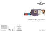
dh
domnick hunter
scientific
LC/MS Nitrogen Generators
dh, domnick hunter, OIL-X and Pneudri are registered
trademarks of domnick hunter limited.
domnick hunter limited has a continuous policy of product
development and although the Company reserves the right
to change specifications, it attempts to keep customers
informed of any alterations. This publication is for general
information only and customers are requested to contact our
Industrial Division Sales Department for detailed information
and advice on a products suitability for specific applications.
All products are sold subject to the Company’s standard
conditions of sale.
www.domnickhunter.com
a member of the domnick hunter group plc
dh
domnick hunter
scientific
domnick hunter limited
Dukesway, Team Valley Trading Estate,
Gateshead, Tyne and Wear,
England NE11 0PZ
Tel: +44 (0)191 402 9000
Telefax: +44 (0)191 482 6296
Copyright domnick hunter limited 2004
Stock No: 176270600 Rev 000
User Guide
8.
Declaration Of Conformity
DECLARATION OF CONFORMITY FOR LCMS12-2, LCMS10 to LCMS40
97/23/EC, 98/37/EC
GB
Name of manufacturer or supplier
domnick hunter ltd.
Full postal address including country of origin
Dukesway, TVTE, Gateshead, Tyne & Wear NE11 0PZ
United Kingdom
Place of issue: Gateshead
Description of product: Nitrogen Gas Generator
Name, type or model, batch or serial number
LCMS12-2, LCMS10 to LCMS40
Directives used
Low Voltage Directive: 73/23/EEC
EMC Directive: 89/336/EEC
Pressure Equipment Directive: 97/23/EC
Machinery Directive: 98/37/EC
93/68/EEC, 92/31/EEC
Standards used, including number, title, issue date and other related documents
Generally in accordance with ASMEVIII Div 1 : 2003 and Pressure Equipment Directive
essential safety requirements
BS EN ISO 12100-1:2003, BS EN ISO 12100-2:2003
EN 61000-6-2:2001, EN 61000-6-3:2000, EN 61000-3-3:1995
BS EN 61010-1:2001
Notified body for PED Regulations:
Conformity Assessment Route : A
Lloyds Register of Shipping
71 Fenchurch St. London EC3M 4BS
EC Type Examination Certificate: TBA
Name of authorised representative
BARRY WADE
Position of authorised representative
Business Improvements Manager
Full postal address if different from above
As above
Declaration
I declare that as the authorised representative, the above information in relation to the
supply / manufacture of this product, is in conformity with the standards and other related
documents following the provisions of the above Directives
Signature of authorised representative
20
Index
7. WARRANTY
This warranty applies to LC/MS NITROGEN GENERATORS and associated parts (the
Equipment) manufactured and supplied by domnick hunter ltd (domnick hunter).
Use of the LC/MS NITROGEN GENERATOR without the recommended inlet air quality or
genuine parts will expressly invalidate the warranty.
Should the Equipment be defective as to materials or workmanship, domnick hunter
warrants that it will remedy such defect. Where the Equipment is a LC/MS NITROGEN
GENERATOR, the warranty period will be 12 months from date of commissioning or 18
months from date of manufacture, whichever is the earlier. In the case of Equipment other
than a LC/MS NITROGEN GENERATOR, the warranty period shall commence from the
date of despatch. Should any defect occur during the warranty period and be notified in
writing to domnick hunter or its authorised distributor within the said period, domnick
hunter will, as its sole option, remedy such defect by repair or provision of a replacement
part, provided that the Equipment has been used strictly in accordance with the instructions
provided with each item of Equipment and has been stored, installed, commissioned,
operated and maintained in accordance with such instruction and with good practice.
domnick hunter shall not be under any liability whatsoever under the warranty, if, before
giving notification in writing to domnick hunter as aforesaid, the Customer or any third
party meddles, interferes, tampers with or carries out work whatsoever (apart from normal
maintenance as specified in the said instructions) in relation to the Equipment or any part
thereof.
Any accessories, parts and equipment supplied by domnick hunter but not manufactured
by domnick hunter shall carry whatever warranty the manufacturer has given domnick
hunter providing it is possible for domnick hunter to pass on such warranty to the
customer.
To claim under the warranty, the goods must have been installed and continually maintained
in the manner specified in the User Guide. Our product support engineers are qualified and
equipped to assist you in this respect. They are also available to make repairs that may
become necessary in which event they will require an official order before carrying out the
work. If such work is to be the subject of a warranty claim, the order should be endorsed for
consideration under warranty.
Where Equipment is sold outside the UK mainland direct to the end user the warranty will
cover parts only. Any substitution of parts not manufactured or approved by domnick
hunter will expressly invalidate the warranty.
19
Page No.
1.
Safety Warnings
1
2.
2.1
Description
Control Options
3
3
3.
3.1
3.2
3.3
Technical Specification
Technical Data
Dimensions
Configuration
4
4
6
6
4.
4.1
4.2
4.3
4.4
4.5
4.6
4.7
Installation
Unpacking
Installation Guidelines
Connection
Initial Start-Up
Normal Operation
Shutdown
Special Functions
7
7
10
10
11
13
13
14
5.
5.1
5.2
Service
Sevice Intervals
Service Kits
15
15
16
6.
Trouble Shooting
18
7.
Warranty
19
8.
Declaration of Conformity
20
Thank you for purchasing a domnick hunter product. Correctly installed, and
maintained in accordance with the recommended service intervals, this product
will provide an uninterrupted supply of nitrogen gas, for the life of the product.
1.
Safety Warnings
6. Troubleshooting
Do not operate this gas generator until the instructions in this manual have been
read and understood by all personnel concerned.
Problem
No power to unit
When handling, installing or operating this gas generator, personnel must employ
safe engineering practices and observe all related regulations, health & safety
procedures and legal requirements for safety.
Indication
Possible Cause
Power On indicator Isolated at supply
not illuminated
Power on switch in ‘OFF’
position
Most accidents that occur during the operation and maintenance of machinery
are the result of failure to observe basic safety rules and procedures. Accidents
can be avoided by recognising that any machinery is potentially hazardous.
domnick hunter can not anticipate every possible circumstance which may
represent a potential hazard. The warnings in this manual cover the most known
potential hazards, but by definition can not be all-inclusive. If the gas generator
user employs an operating procedure, item of equipment or a method of
working which is not specifically recommended by domnick hunter the user
must ensure that the gas generator will not be damaged or made a potential
hazard to persons or property.
Reduced delivery Outlet pressure
pressure
gauges
The gas generator will have warning/hazard labels attached, a list of warning
labels and their meaning is given below: -
General Warning
Read Manual
Fuse blown
Check fuse & replace
Power lead not
connected
Check lead connected
& connect
Loose connection inside
generator
Consult domnick hunter
Service Dept.
Connected incorrect
voltage supply
Check rating plate
voltage for suitability
Compressor failure
(option 1 units only)
Check compressor is
running, consult domnick
hunter Service Dept.
Compressor
over-heating due to
insufficient ventilation
Check ventilation
clearance & rectify
Leaking outlet pipe-work
Check pipe-work
& rectifier
Pressure regulator set low
Check pressure
regulator setting & reset
Service interval
exceeded
Check service timers
and service
Leaking inlet pipe-work
(option 0 units only)
Check pipe-work &
rectify
Inlet pressure set low
Check inlet pressure &
increase
Check pipe-work
diameter & replace
Inlet (option 0 units only) or
outlet pipe-work diameter
too small
Demand greater than
supply capability
Risk of Electric Shock
Reduced purity
Pressurised Components on System
May Start Automatically Without Warning
Downstream
monitoring
Check pipe-work
& rectify
Unsuitable pipe-work
used on outlet
Check pipe-work
and replace
Generator recently
brought online
Check & allow at least
6-hours for purity to be
achieved
Check inlet air
quality & rectify
Use Lifting Equipment
1
Check requirements
against original sizing data
Leaking outlet pipe-work
Inlet air supply IS08573.1
2001 air quality class 2.-.1
(option 0 units only)
Use Forklift Truck
Action Required
Check isolator &
switch on
Check power on
switch & switch on
18
SERVICE KIT A - FILTER OVERHAUL
SERVICE KIT C - VALVE OVERHAUL
SERVICE KIT C * - AIR INLET OVERHAUL
Nitrogen is not a poisonous gas but, in a concentrated form, there is a risk of
asphyxiation. The gas generator produces a flow of nitrogen (and air on some
options) which quickly disperses in the atmosphere. However, do not directly
inhale the output gas from the outlet pipes.
The gas generator is classified as non-hazardous for transportation purposes
and as non-flammable for fire regulations. Any fire should be fought by means
appropriate to the material causing the fire with the exception being the use of
water.
Ensure that the product is de-pressurised and electrically isolated, prior to
carrying out any maintenance activity.
This product should be installed in accordance with the recommendations
outlined in this manual. Commissioning and service should be undertaken by a
domnick hunter trained and approved engineer to maintain warranty.
Extended warranty and tailored service contracts are available for this product.
Please contact your local domnick hunter sales office for a tailored service
agreement to meet your specific requirements.
Note: Any interference with the calibration warning labels will invalidate the gas
generator’s warranty and may incur costs for the re-calibration of the gas
generator.
SERVICE KIT A - FILTER OVERHAUL
SERVICE KIT B – COMPRESSOR CHANGE
Details of your nearest domnick hunter sales office can be found at
www.domnickhunter.com.
17
2
2.
Description
domnick hunter LC/MS Nitrogen Generators are designed to provide a constant
supply of nitrogen gas to a pre-selected purity (and clean dry compressed air on
some options).
The technology used to produce a continuous flow of nitrogen (and clean dry
compressed air on some options) is pressure swing adsorption (PSA). This
technology uses a combination of molecular sieves to selectively remove oxygen
and other contaminants from the compressed air, leaving nitrogen.
The column(s) of molecular sieve alternate between purification and regeneration
modes to ensure a continuous nitrogen supply.
Service
Typical Recommended Maintenance Intervals (Run Hours)
A
4000 8000 12000 16000 20000 24000 28000 32000 36000 40000
B
Service
Typical Recommended Maintenance Intervals (Run Hours)
A
44000 48000 52000 56000 60000 64000 68000 72000 76000 80000
B
C
5.2 Service Kits
Air Supply
The gas generators are available with integrated compressor (option 1) or
without integrated compressor (option 0). Option 0 units require a supply of
compressed air to ISO8573.1 2001 air quality class 2.-.1
ii)
C
2.1 Control Options
i)
Rapid Cycle Mode
Service
Variant
A
B
ALL
115V / 50-60Hz
230V / 50-60Hz
115V / 50-60Hz
230V / 50-60Hz
115V / 50-60Hz
230V / 50-60Hz
C
The purity of the nitrogen gas will deteriorate when the generator is first returned
online following a period of time in Standby. The time taken to return to
pre-selected purity is dependent on the period of time that the gas generator was
in Standby, the table below gives typical purity recovery times: -
C*
Service Kit Number
1
2
3
4
5
6
7
606272251
606272261
606272253
606272263
606272255
606272265
606272257
C * - Additional valve service kit also required with Service kit C for Opt 0 Units.
Time in Standby
(hours)
Typical Purity
Recovery Time
(minutes)
20
20
20
30
60
4
12
24
48
48+
3
16
5.
Service
Rapid Cycle Mode enables the gas generator to flush impurities from the system
following a period of time in Standby, enabling the pre-selected purity to be
achieved in a faster time.
5.1 Service Intervals
Check POWER ON indicator located
Generator on control panel is illuminated and
cycles from red to green
Check drain valve is discharging on a
Generator regular basis.
Check for leaks
Generator
Generator Check pressure gauges during
operation
Ensure there is ventilation clearance
Generator around generator
Check condition of electrical supply
Generator cables and conduits
Replace filters
Generator Recommended Service A
Replace compressor (Integral
Generator Compressor Units ONLY)
Recommended Service B
Replace Valves
Generator Recommended Service C
C - Check
R – Replace
15
12 Months
8000 Hrs
36 Months
24000 Hrs
6 Months
4000 Hrs
Operation
Weekly
Component
Typical Recommended
Maintenance Interval
Daily
Description Of Maintenance Required
The gas generator can remain in Rapid Cycle Mode for up to 15 minutes, during
which time no nitrogen gas is delivered to the application.
Important: If Rapid Cycle Mode is included on your gas generator and the above
performance characteristics are unacceptable for your application, can be
disabled via the keypad, refer to section 4.5 (Normal Operation) of this manual.
3
Technical Specification
3.1 Technical Data
C
Parameter
Units
LCMS 15
LCMS 20
LCMS 30
LCMS 40
Air Source
C
Integral Compressor
C
Inlet Air Pressuure
barg
(psi g)
C
Maximum Inlet Air
Temperature
Inlet Air Capacity
ºC
(ºF)
l/min
(CFM)
ISO8573.1
2001
C
Inlet Air Quality
C
No
Yes
No
Yes
No
Yes
No
9.0
(130.5)
-
9.0
(130.5)
-
9.0
(130.5)
-
9.0
(130.5)
-
2.-.1
40
(104)
2.-.1
85
(3.0)
-
15
(0.53)
15
(0.53)
2.-.1
85
(3.0)
-
2.-.1
85
(3.0)
-
20
(0.71)
20
(0.71)
30
(1.01)
30
(1.01)
40
(1.41)
<2
<1
-
1/4”
Swagelok
-
Nitrogen (N2)
R
R
R
Outlet Flow
l/min
(CFM)
Maximum Outlet
Pressure
Purity
(with repect to o2)
barg
(psi g)
%
7
(101.5)
<0.5
<1
Mechanical Connections
Air Inlet
Insert
Inlet
1/4”
Swagelok
-
1/4”
Swagelok
4
-
1/4”
Swagelok
Symbol
Nitrogen Outlet
1/8”
Swagelok
Nitrogen Outlet
with Mass Flow
controller
1/8”
Swagelok
4.7 Special Functions
Bypassing Mass Flow Controller
The integral mass flow controller should only be bypassed if there is a mass flow
controller fitted to the inlet of the downstream equipment, and the mass flow
controller is set to the maximum outlet flow of the gas generator.
Electrical Connections
115V Variants
Connection Type
115+ / -10% / 50Hz / 60Hz / 1phase +
protective earth
Operating Voltage
Range
V
Maximum Current
A
1.6
11.6
1.6
11.6
1.6
11.6
1.6
Fuse Rating
A
2.0
Anti
Surge
12.5
Anti
Surge
2.0
Anti
Surge
12.5
Anti
Surge
2.0
Anti
Surge
12.5
Anti
Surge
2.0
Anti
Surge
230V Variants
Connection Type
b)
Remove the service cover from the gas generator and locate the 3-way
bypass valve. The bypass valve handle should be in the down position (B),
this will direct the gas flow through the integral mass flow controller.
A
2
230+/-10% / 50Hz / 60Hz / 1phase +
protective earth
V
Maximum Current
A
0.8
5.8
0.8
5.8
0.8
5.8
0.8
Fuse Rating
A
2.0
Anti
Surge
6.3
Anti
Surge
2.0
Anti
Surge
6.3
Anti
Surge
2.0
Anti
Surge
6.3
Anti
Surge
2.0
Anti
Surge
Maximum
Ambient
Temperature
Shutdown the gas generator following the procedure outlined in 4.6 above.
IEC320
Operating Voltage
Range
Environment
Minimum Ambient
Temperature
a)
IEC320
ºC
(ºF)
+5
(41)
ºC
(ºF)
40
(104)
5
1
B
Valve in Bypass Position
c)
Rotate the valve handle clockwise to the up position (A), this will
redirect the gas flow bypassing the integral mass flow controller.
d)
Remove blanking plug from port 1, and screw into port 2.
e)
Connect the application pipe-work to port 1.
f)
Replace the service cover.
g)
Set the external mass flow controller to the maximum outlet flow of the gas
generator.
h)
Start up the generator.
14
4.5 Normal Operation
3.2
The gas generator is designed to run continuously without any intervention.
Dimensions
Dimensions
Height
If Rapid Cycle Modes are activated, the gas generator will not supply nitrogen
gas to the application for up to 15-minutes following a period of time.
mm
(inches)
705
(27.8)
Width
510
(20.1)
To disable Rapid Cycle Mode follow instructions below: -
Depth
mm
(inches)
mm
(inches)
559
(22.1)
826
(32.5)
559
(22.1)
826
(32.5)
760
(29.9)
826
(32.5)
760
(29.9)
a)
Weight
kg
(lbs)
89
(196)
129
(284)
89
(196)
129
(284)
135
(298)
129
(284)
135
(298)
b)
c)
d)
Return the generator to Standby Mode, by following the on screen
instructions.
When “STANDBY” is displayed, press and hold the Down Key and the
Return Key for 5-seconds.
Switch Rapid Cycle Mode on and off using the Up Key and the Down Key.
Return to “STANDBY” by pressing the Return Key.
3.3
Configuration
In the event of any kind of interruption to the operation, the unit must be run for
1-hour offline (i.e. no gas to application) to enable the purity to recover.
4.6 Shutdown
The generator will contain a residual internal pressure that must be released if
unit is to be shipped or serviced. In order to depressurise the unit follow the
instructions below: a)
b)
Close isolation valves fitted to the system (refer to 4.4 Initial Start-Up –
System Configurations).
Return the generator to Standby Mode, by following the on screen
instructions.
Note: When the generator is shutting down the unit may continue to run for up to
10-minutes. This will permit the unit to finish its cycle and ensures that the inlet
pipe-work & columns are fully depressurised
c)
Switch off the electrical supply to the generator and disconnect.
d)
Disconnect the inlet pipe-work (non-compressor models only).
e)
Blank the inlet, outlet and drain ports.
f)
Allow 30-minutes for the compressor/s to cooldown (integral compressor
units only).
13
6
4.0 Installation
4.1 Unpacking
WARNING: Heavy unit not to be manually lifted.
a)
Using appropriate sized pallet truck position the packing crate on a level
surface leaving enough surrounding space for unpacking & removal of the
unit. Once positioned in a suitable location remove & dispose of all
strapping.
b)
Use the tool provided & follow this procedure when removing each
fastening clip. Place one hand at the base of the clip holding it firmly in
place. With the other hand place the end of tool underneath one end of the
clip & prise out using an anti-clockwise motion.
c)
Remove the lid panel.
d)
Remove either one of the larger side panels.
e)
Remove the panel covering the back face of the unit (ply wood panel).
Retain this panel along with one fastening clip to use as a ramp in
procedure (k)
f)
Remove the other remaining larger side panel.
g)
Remove the final panel covering the front face of the unit.
h)
Remove all foam inserts.
i)
Using ply wood panel from procedure (e) place end with slot for clip onto
the recess of the crate base (side with slot for clip), creating a ramp.
j)
Using one of the fastening clips removed, insert the longest end into the
slot on the ramp & push remaining end into the slot on the base. Now test
the ramp to ensure it is securely fastened.
k)
Leave the unit in the bubble wrap &, whilst supporting the unit, slowly wheel
down the ramp.
l)
Finally remove & dispose of the bubble wrap packing ensuring not to
scratch the paint work.
Care should be taken and inspection undertaken during unpacking to
ensure that the gas generator is not damaged.
7
System Configurations
12
4.4 Initial Start-Up
a
b
c
d
e
f
Should be undertaken by a domnick hunter trained and approved service
engineer.
1.
Switch on electrical power to the generator. The LCD & LED on the front
console will illuminate.
2.
Start the gas generator by pressing the return key on the console.
3.
The generator will now display hours run, cycle from Red LED to Green
LED and will produce an uninterrupted supply of reduced purity nitrogen
gas. If the unit has Rapid Cycle Mode fitted and activated, “Rapid Cycle” will
be displayed for the first few cycles and no gas will be delivered during this
period.
Note: The generator should be run for a minimum of six hours prior to
connection to the application, to ensure that the required purity of gas is
achieved.
4.
Ensure that the drain valve is discharging on a regular basis, if the drain
line is blocked purity will not be achieved.
5.
After a minimum of six hours the gas generator will produce an
uninterrupted supply of high purity nitrogen gas (and clean dry compressed
air on some models) and can now be connected to the application. Ensure
that pipe-work is adequately supported.
6.
Identify the required system configuration from those shown on the next
page and connect to the application, using either copper or stainless steel
tubing. Ensure that the correct tube is connected to the N2 Out (and Dry
Air Out on some models) ports on the gas generator.
Note: The application supply pipe-work will need to be flushed through for
one hour for every 10-metres of pipe-work, before normal purity is
achieved.
11
8
g
h
i
j
4.2 Installation Guidelines
1.
Only a domnick hunter trained and approved service engineer should
undertake commissioning.
2.
Ensure that the gas generator is correctly sized for the application.
3.
Identify a suitable location for the gas generator, ensuring the following: -
a)
The gas generator should be installed on a flat surface
b)
Environmental restrictions (refer to section 3.1 Technical Specification) a
re taken into consideration.
c)
The gas generator should be located as close to the application as
possible.
d)
There is at least 100mm clearance, on both sides and rear of the generator,
for ventilation.
e)
Isolation valves should be fitted to the system (refer to 4.4 Initial Start-Up
– System Configurations), these must be accessible when generator is
installed.
f)
The mounting surface is capable of supporting the weight of the gas
generator (refer to section 3.2 Dimensions).
g)
There is sufficient space around the gas generator for maintenance
activities.
4.
Ensure that the inlet air supply for non-compressor variants is treated to
ISO8573.1 2001 air quality class 2.-.1
4.3 Connection
k
l
9
1.
Remove blanking plugs and install fittings supplied with generator but do
not connect to the application at this stage.
2.
Ensure all ports and fittings are free from blockages and debris.
3.
The Air Inlet connection of non-compressor units should be connected to
an ISO8573.1 2001 air quality class 2.-.1 compressed air supply. Ensuring
that all pipe-work is adequately supported.
4.
Check rating plate for correct supply voltage and frequency. Connect the
mains lead supplied to the electrical connector on the side of the generator
and connect to a suitably rated power supply complete with protective
earth.
10