1
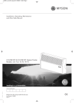
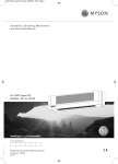
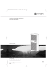
25796 Finesse Installation Manual A5 08/10/2013 13:00 Page 1
MYSON Eastern Avenue, Team Valley, Gateshead, Tyne & Wear NE11 0PG, UK
T: 0845 402 3434, F: 0191 491 7568, [email protected], www.myson.co.uk
FINESSE.
INSTALLATION, OPERATING
& INSTRUCTION MANUAL
Please leave this manual with the end user.
Class 1 - 230V - 50 Hz
heatingthroughinnovation.
01.01.2014
heatingthroughinnovation.
25796 Finesse Installation Manual A5 08/10/2013 13:00 Page 3
FINESSE
Contents
03
1.0 Warnings & Safety Information
1.0
Warnings & Safety Information
03
SAFETY INFORMATION
2.0
General Information
05
3.0
Warranty
05
4.0
Installation
06
5.0
Maintenance, Repair & Disposal
07
6.0
Waste Disposal According to The WEEE Directive (2002/96/EC)
07
7.0
Operating Instructions
08
7.1
Stand Alone Radiator
08
7.2
Radiator Connected to a Wireless Wall Receiver & RF Programmer
09
7.3
Other Functions
10
This appliance can be
used by children aged
from 8 years and above
and persons with reduced
physical, sensory or
mental capabilities or
lack of experience and
knowledge, if they have
been given supervision
or instruction concerning
use of the appliance in a
safe way and understand
the hazards involved.
Children shall not play with
the appliance. Cleaning
and user maintenance
shall not be made by
children unless they
are older than 8 and
supervised.
Keep the appliance and
its cord out of reach of
children aged less than
8 years.
8.0
Technical Characteristics
10
9.0
Optional Extra - RF Programmer
11
Children of less than
3 years should be kept
away from the unit unless
continuously supervised.
Children aged from
3 years and less than
8 years shall only switch
on/off the appliance
provided that it has been
placed or installed in
its normal operating
position and they have
been given supervision
or instruction concerning
use of the appliance in a
safe way and understand
the hazards involved.
Children aged from
3 years and less than
8 years shall not plug in,
regulate, clean the
appliance or perform
user maintenance.
25796 Finesse Installation Manual A5 08/10/2013 13:00 Page 5
04
FINESSE
FINESSE
1.0 Warnings & Safety Information (cont...)
CAUTION
Some parts of this product
can become very hot and
cause burns. Particular
attention has to be given
where children and
vulnerable people are
present.
In order to avoid
overheating, do
not cover the radiator.
“Do not cover” means
that the radiator must
not be used for drying
clothes, for example,
by placing them directly
on the radiator.
IMPORTANT SAFETY
INSTRUCTIONS!
Before starting work disconnect power supply!
All installation work and wiring work related to
the radiators, thermostats and programmers
must be carried out only when de-energized.
The appliance should be installed by and
commissioned by qualified professionals only.
Make sure to adhere to valid safety regulations.
Any repairs or maintenance within the warranty
period should be carried out only by approved
service engineers confirmed by MYSON.
For the correct installation of radiators it is
essential that the fixing of the radiator is
carried out in such a way that it is suitable for
intended use AND predictable misuse. A
number of elements need to be taken into
consideration including the fixing method used
to secure the radiator to the wall, the type and
condition of the wall itself, and any additional
potential forces or weights, prior to finalising
installation. IN ALL CASES IT IS STRONGLY
RECOMMENDED
THAT
A
SUITABLY
QUALIFIED PROFESSIONAL INSTALLER OR
SIMILAR TRADESPERSON CARRIES OUT
THE INSTALLATION.
2.0 General Information
l
This appliance is a sealed electric radiator
designed for fixed wall-mounted installation.
l
This appliance conforms to the standards
EN 60 335-1 and EN 60 335-2-30.
l
This appliance is class 1 and splash resistant
(IP44).
l
This appliance complies with the European
Directive 2004/108/EC (CE Marking on all
appliances).
l
This unit is supplied complete with a
connection cable and wall brackets.
Cable Hook Assembly
Back of Radiator
PLEASE NOTE: The fixing materials provided are only
intended for installation on walls made of solid wood,
bricks, concrete or on timber-frame stud walls where the
fixing is into the timber. All walls being considered should
have no more than a maximum of 3mm wall finishing. For
walls made of other materials, for example hollow bricks,
please consult your installer and/or specialist supplier.
ONCE AGAIN, IF YOU ARE UNSURE, IT IS
STRONGLY RECOMMENDED THAT A SUITABLY
QUALIFIED PROFESSIONAL INSTALLER OR SIMILAR
TRADESPERSON CARRIES OUT THE INSTALLATION.
1. Thermostat Control
4. Power Cable
The radiator is equipped with an overheat
protection that cannot be reset (melt fuse). This
overheat protection disconnects the current if
the radiator becomes too hot (e.g. when
covered).
2. Power On/Off Switch
If the supply cord is damaged, it must be
replaced by the manufacturer, his service agent
or similar qualified persons in order to avoid a
hazard.
The radiator is filled with an exact amount of
environmental friendly vegetable oil. Any
repairs that require the radiator to be opened
shall therefore only be carried out by the
manufacturer or his approved agent. Please
contact MYSON in case of leakage.
05
3. Room Temperature Sensor
3.0 Warranty
The product is covered by a 10 year warranty
except for the electrical and electronic
components that are covered by a 2 year
warranty.
25796 Finesse Installation Manual A5 08/10/2013 13:00 Page 7
06
FINESSE
FINESSE
4.0 Installation
4.0 Installation (cont...)
FINESSE Double Panel (refer to figure 2)
POSITIONING
l
l
l
The radiator must be positioned horizontally,
the right way up on the wall in order for it to
function correctly. Never switch the radiator
on in any other position as this will damage
the electrical element.
Min.100mm
The radiator must be positioned according
to the applicable standards and the
minimum distances as specified in figure 1
should be carefully observed.
The radiator must not be
underneath an electric socket.
Min.100mm
Min.100mm
Mark out the distance between the brackets
and the positions for the screw holes as
shown in figure 2 and the dimension tables
at the top of page 7, and ensure the safety
clips are used (see figure 3).
90
163
Length (mm)
400
500
650
800
950
1000
1250
1300
1600
2000
A
109
160
160
160
160
160
160
160
160
160
B
203
203
355
508
660
711
965
1016
1320
1727
l
If the radiator is installed in a bathroom or
shower room, it must be protected with a
residual current device (RCD) with a rated
residual current not exceeding 30 mA.
l
The radiator should be connected by a
suitable and qualified electrician. Please
refer to the wiring diagram (figure 5) for the
connection of the radiator.
Figure 5.
Wire Colours
BR = Brown
BK = Black
BL = Blue
G/Y = Green/Yellow
5.0 Maintenance, Repair & Disposal
l
Use only a damp cloth for cleaning and
wiping of the radiator which should be
switched off at this time.
l
When scrapping the radiator, follow the
regulations concerning the disposal of oil.
OUTSIDE ZONES
6.0 Waste Disposal According to The WEEE Directive (2002/96/EC)
Zone 2
2.25m
Zone 1
Zone 2
FIXING
l
Step 2
This product is splash resistant with an IP44
rating. This must be considered when
installing in a location containing a bath or
shower, as defined by BS 7671.
The radiator may be positioned in zone 2
(figure 4) of the bathroom, in so far as no
operating controls (button, switch, etc.) are
in reach of persons in the bath or under
the shower.
D
The radiator must be connected to the
electrical supply, using a switched fused
spur with 3mm separation on all poles.
C
Step 1
Figure 3.
3m
l
205
l
D
H
l
500
135
The electrical installation must comply with
local or national regulations.
B
FLOOR
300
C
l
Safety Clip-on Brackets
L
A
Height (mm)
CONNECTION
located
Figure 1.
Figure 2.
07
Zone 0
0.6m
m
0.6
Figure 4.
Waste disposal according to the
WEEE Directive (2002/96/EC).
The symbol on the product label
indicates that the product may
not be handled as domestic
waste, but must be sorted
separately. When it reaches the end of its
useful life, it shall be returned to a collection
facility for electrical and electronic products. By
returning the product, you will help to prevent
possible negative effects on the environment
and health to which the product can contribute
if it is disposed of as ordinary domestic waste.
For information about recycling and collection
facilities, you should contact your local
authority/municipality or refuse collection
service or the business from which you
purchased the product. Applicable to countries
where this Directive has been adopted.
25796 Finesse Installation Manual A5 08/10/2013 13:00 Page 9
08
FINESSE
FINESSE
7.0 Operating Instructions
7.2 Radiator Connected to a Wireless Wall Receiver & RF Programmer
The On/Off button (see page 5) is located at
the bottom of the control side of the radiator.
The radiator should only be switched “on”
when it is correctly installed and secured to
the wall brackets. In the “on” position, LED A
(figure 6) turns green.
When connected to a wireless wall receiver
(figure 7), select the automatic operation
mode.
AUTOMATIC MODE
This mode is to be used during periods of
normal occupancy.
l
7.1 Stand Alone Radiator
Select one of the following operation modes
using Dial D (figure 6):
A
COMFORT MODE
This mode is to be used during periods of
normal occupancy.
l
l
Rotate dial “D”
around to the
symbol.
l
Wire Colours
BR = Brown
BK = Black
BL = Blue
G/Y = Green/Yellow
D
(Sun)
Select the desired
room temperature
between 5 and 37°C
(scale 1 to 6) using
dial “B”.
Rotate dial “D”
around to the
(Moon) symbol.
B
C
REDUCED MODE
This mode is to be used at night-time or when
the house is unoccupied for a few hours or
more. This mode will lower the temperature of
the room by 3.5°C from the “Comfort mode”
set temperature.
l
09
E
Figure 7.
l
Select the desired
room temperature
during periods of
normal occupancy
between 5 and 37°C
(scale 1 to 6) using
dial “B”.
Rotate dial “D” within the area covered by
the
(Clock) symbol. The value on this
scale indicates the desired temperature
reduction during the night or during shorter
periods of absence.
When the house is unoccupied for longer
periods (e.g. holiday) you can override the
clock program by rotating dial “D” around
to “Reduced” or “Frost protection” mode.
Figure 6.
Optional Extras
FROST PROTECTION MODE
This mode is to be used when the house is
un-occupied for extended periods of time. The
lowest temperature the room can reach is 7°C.
l
Rotate dial “D”
around to the
(Snowflake) symbol.
RF Programmer
The MYSON FINESSE radiator can be used
as a stand alone radiator or can be
connected to radio frequency programmer
via a wireless wall receiver. Please refer to
section 9 for more information.
25796 Finesse Installation Manual A5 08/10/2013 13:00 Page 11
10
FINESSE
FINESSE
7.3 Other Functions
l
11
9.0 Optional Extra - RF Programmer
The switch (E, figure 6) at the bottom of
the control panel can be used to limit the
output of the heating element in the front
panel and as a consequence the surface
temperature of the front panel.
60°C max.
75°C max.
E.g. A 1000 Watt double panel with the switch
E on the position corresponding to 60°C will
deliver maximum 800 Watts. A 2000 Watt
double panel with the switch E on the position
corresponding to 75°C will deliver maximum
1800 Watts. These values should be considered
when selecting the number and type of panels
to cover the calculated heat losses.
l
90°C max.
When considering the permanent use of the
radiator at 60°C or 75°C maximum, the
following correction factor should be
applied for the output.
l
Install and plug the radiator into a
switched fused spur along with the wireless
wall receiver. NB: The RF programmer will
not work without the wireless wall receiver.
Both LED indicators (A and C, figure 6)
indicate the working mode of the radiator.
RF Programmer
LED A
Green
Radiator switched on
Red
Radiator heating
Red blinking
Sensor problem
Surface
Temperature
Double
panel
60°C max
~0.80
Off
Comfort mode
75°C max
~0.90
Reduced mode
90°C max
1
Green blinking
(4 times-blank)
Wireless
Wall Receiver
LED C (only when external programmer connected)
8.0 Technical Characteristics
Switched Fused Spur*
Measured temperature precision
0.1°C
Operating temperature
-10°C + 50°C
Setting temperature range
+5°C + 30°C
Control characteristics
PWM
Electrical protection
Class 1 – IP44
Power supply
230 VAC – 50 Hz
Controls consumption
~3.5 W
Output
TRIAC 230 VAC 8A
The thermostat has been designed to
comply with the following Directives and
Standards.
l
l
l
l
l
l
EN 60730-01
EN 61000-6-1
EN 61000-6-3
EN 61000-4-2
LV Directive 2006/95/CE
EMC Directive 2004/108/CE
Figure 8.
l
Install the RF programmer in a suitable
location.
l
Connect the wireless wall receiver to the RF
programmer using the manufacturers
instructions on both products.
*When installing in a bathroom or wet room, please refer
to the installation positions in Section 4.0 Installation on
page 6.
PLEASE REFER TO THE MANUFACTURERS
MANUAL
FOR
FULL
INSTALLATION
INSTRUCTIONS.