1
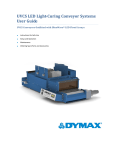
DYMAX BlueWave® LED DX-1000 User Guide Small-Area LED Light Source ■ Instructions for Safe Use ■ Setup and Operation ■ Maintenance ■ Ordering Spare Parts and Accessories 2 DYMAX BlueWave® LED DX-1000 User Guide About DYMAX UV/Visible light-curable adhesives. Systems for light curing, fluid dispensing, and fluid packaging. DYMAX manufactures industrial adhesives, light-curable adhesives, epoxy resins, cyanoacrylates, and activator-cured adhesives. We also manufacture a complete line of manual fluid dispensing systems, automatic fluid dispensing systems, and light-curing systems. Light-curing systems include LED light sources, spot, flood, and conveyor systems designed for compatibility and high performance with DYMAX adhesives DYMAX adhesives and light-curing systems optimize the speed of automated assembly, allow for 100% in-line inspection, and increase throughput. System designs enable stand-alone configuration or integration into your existing assembly line. Please note that most dispensing and curing system applications are unique. DYMAX does not warrant the fitness of the product for the intended application. Any warranty applicable to the product, its application and use is strictly limited to that contained in the DYMAX standard Conditions of Sale. DYMAX recommends that any intended application be evaluated and tested by the user to insure that desired performance criteria are satisfied. DYMAX is willing to assist users in their performance testing and evaluation by offering equipment trial rental and leasing programs to assist in such testing and evaluations. Data sheets are available for valve controllers or pressure pots upon request. DYMAX BlueWave® LED DX-1000 User Guide Contents Introduction .................................................................................................................................................... 4 Introduction to the User Guide ....................................................................................................................................... 4 Where to Get Help .......................................................................................................................................................... 4 DYMAX Contact Information ........................................................................................................................................... 4 Safety.............................................................................................................................................................. 5 General Safety Considerations ........................................................................................................................................ 5 Specific Safety Considerations ......................................................................................................................................... 5 DYMAX UV Light-Curing System Safety Considerations .................................................................................................. 6 Product Overview ........................................................................................................................................... 8 Description of the BlueWave® LED DX-1000 ................................................................................................................... 8 Special Features and Benefits of the BlueWave® LED DX-1000 System .......................................................................... 9 Intensity Control Feature ................................................................................................................................................ 9 Validation ...................................................................................................................................................................... 10 Front Control Panel ....................................................................................................................................................... 11 Back Panel ..................................................................................................................................................................... 12 Assembly and Setup ...................................................................................................................................... 13 Unpacking and Inspecting Your Shipment ..................................................................................................................... 13 Parts Included in the BlueWave LED DX-1000 Small-Area LED Light Source ................................................................. 13 System Connections ...................................................................................................................................................... 14 Operating the LED Light ................................................................................................................................ 15 Powering up the Controller ........................................................................................................................................... 15 Using Advanced and Optional Features ........................................................................................................ 16 Using the Optional Stand............................................................................................................................................... 16 Using the PLC Interface ................................................................................................................................................. 18 Cleaning and Maintenance ........................................................................................................................... 20 System Cleaning ............................................................................................................................................................ 20 Error Codes and Troubleshooting .................................................................................................................. 22 Spare Parts and Accessories .......................................................................................................................... 24 Options/Accessories ...................................................................................................................................................... 24 Spare/Replacement Parts .............................................................................................................................................. 25 Specifications ................................................................................................................................................ 26 Specifications................................................................................................................................................................. 26 Warranty ...................................................................................................................................................... 28 Index ............................................................................................................................................................. 29 3 4 DYMAX BlueWave® LED DX-1000 User Guide Introduction Introduction to the User Guide This guide describes how to use the DYMAX BlueWave® LED DX-1000, (PN 40560) Small-Area LED Light Source. Sections in this guide describe how to assemble, use, and maintain the light source safely and efficiently. Intended Audience DYMAX prepared this user guide for experienced process engineers, technicians, and manufacturing personnel. If you are new to high-intensity LED light sources and do not understand the instructions, contact DYMAX Applications Engineering to answer your questions before using the equipment. Where to Get Help Additional resources are available to ensure a trouble-free experience with our products: ■ Detailed product information on www.dymax.com ■ Customer Support and Applications Engineering teams available by phone and email ■ DYMAX adhesive product data sheets on our website ■ Material safety data sheets (MSDS) sheets provided with shipments of DYMAX adhesives DYMAX Contact Information You can contact DYMAX Customer Support and Applications Engineering in the United States, Monday through Friday, from 8:00 a.m. to 5:00 p.m. Eastern Standard Time. You can also email DYMAX at [email protected]. DYMAX Global Locations DYMAX Corporation 318 Industrial Lane Torrington, CT 06790 USA Phone: 860.482.1010 Fax: 860.496.0608 www.dymax.com DYMAX Asia (H.K.) Ltd Flat B, 9/F, Yeung Yiu Chung (No. 8) Ind. Bldg. No. 20 Wang Hoi Road, Kowloon Bay Kowloon, Hong Kong Phone: +852.2460.7038 Fax: +852.2460.7017 www.dymax.com.cn DYMAX Europe GmbH Kasteler Strasse 45 Building G 359, 65203 Wiesbaden, Germany Phone: +49 (0) 611.962.7900 Fax: +49 (0) 611.962.9440 www.dymax.de DYMAX UV Adhesives & Equipment (S.Z.) Co. Ltd Room 617 & 618, South Tower Cangsong Building, Terra 6th Road Futian District, Shenzhen China 518040 Phone: +86.755.83485759 Fax: +86.755.83485760 www.dymax.com.cn DYMAX Korea LLC #903, CCMM B/D, 12 Yeoido-Dong Youngdung Po-Gu Seoul, Korea, 150-869 Phone: 82.2.784.3434 Fax: 82.2.784.5775 www.dymax.co.kr DYMAX BlueWave® LED DX-1000 User Guide Safety ! WARNING! If you use this LED light source without first reading and understanding the information in this user guide, injury can result from exposure to high-intensity light. To reduce the risk of injury, read and ensure you understand the information in this user guide before assembling and operating the DYMAX LED light source. General Safety Considerations All users of DYMAX LED light sources should read and understand this user guide before assembling and using the system. To learn about the safe handling and use of light-curable formulations, obtain and read the MSDS for each product. DYMAX includes an MSDS with each adhesive sold. In addition, fluid product MSDS are available on our website. Specific Safety Considerations The BlueWave® LED DX-1000 is designed to maximize operator safety and minimize exposure to light-curing energy. To use the unit safely, it must be set up and operated in accordance with the instructions in this user guide. Please also read and understand the safety considerations unique to LED-curing systems as described below. ! WARNINGS! Looking directly at the high-intensity light emitted by the BlueWave LED DX-1000 can result in eye injury. To prevent eye injury, never look directly at the high-intensity light and always wear protective goggles (provided). Operating the light with the Lens Cover in place can result in overheating and equipment damage. To prevent equipment damage, never operate the unit with the Lens Cover in place. Removing the cover from the BlueWave LED DX-1000 Controller can result in electrical shock. To prevent electrical shock, never remove the cover from the DX-1000 Controller. If you block the air flow from the LED Irradiator Head or Controller Cooling Fans, equipment damage and malfunction can result. To prevent damage and malfunction, ensure there is adequate space at the Cooling Fan Outlets to allow the free flow of air. 5 6 DYMAX BlueWave® LED DX-1000 User Guide DYMAX UV Light-Curing System Safety Considerations Operators must understand these three concepts to use the LED light source safely: ■ ■ ■ UV exposure High-temperature surfaces Bright visible light Each is described below. UV Exposure Standard DYMAX UV light-curing systems have been designed primarily to emit UVA energy (Figure 1). The energy emitted from the DYMAX BlueWave® LED DX-1000 system is in the upper end of the UV portion of the spectrum. UVA energy is generally considered the safest of the three UV ranges: UVA, UVB, and UVC. Although OSHA does not currently regulate UV light exposure in the workplace, the American Conference of Governmental Industrial Hygienists (ACGIH) does recommend Threshold Limit Values (TLVs) for ultraviolet light. The strictest interpretation of the TLV (over the UVA range) for workers’ eyes and skin allows continuous 2 exposure up to 1 mW/cm (intensity). Unless you are placing bare hands into the curing area, it is unusual to 2 exceed these limits. To put 1 mW/cm limit into perspective, a cloudless summer day will typically exceed 2 3 mW/cm of UVA light, and also include the more dangerous UVB light (primarily responsible for sun tans, sun burns, and skin cancer) as well. Figure 1. UV Spectrum Checking the Workstation The human eye cannot detect "pure" UV light, only visible light. A radiometer should be used to measure stray UV light to confirm the safety of a UV light-curing process. A workstation that exposes an operator to more 2 than 1 mW/cm of UVA continuously should be redesigned. DYMAX BlueWave® LED DX-1000 User Guide Protecting Operators Light-curing technology can be a regulatory compliant, "worker-friendly" manufacturing process when the proper safety equipment and operator training is utilized. There are two ways to protect operators from UV exposure: shield the operator and/or shield the source. Shield the Operator — UV-Blocking Eye Protection - UV-blocking eye protection is recommended when operating UV light-curing systems. Both clear and tinted UV-blocking eye protection is available from DYMAX. UV-Blocking Skin Protection — Where the potential exists for UV exposure upon skin, opaque, UV-blocking clothing, gloves, and full-face shields are recommended. Shield the Source of UV Any substrate that blocks UV light can be used as a shield to protect workers from stray UV light. The following materials can be used to create simple shielding structures: Rigid Plastic Film — Transparent or translucent/UV-blocking plastics (typically polycarbonate or acrylic) are commonly used to create shielding where some level of transparency is also desired. Flexible Film — Translucent UV-blocking, flexible urethane films can be used to quickly create workstation shielding. This UV-blocking, flexible urethane film is available from DYMAX, call for assistance. NOTE: The BlueWave® LED DX-1000 includes UV-blocking flexible film that is affixed with a magnetic strip that can be used to attach it to the LED Head and trimmed to suit your application. High-Temperature Surfaces Surfaces exposed to high-intensity curing lights may rise in temperature. The intensity, distance, exposure time, cooling fans, and composition of the surface can all affect the rise in surface temperature. In some cases, exposed surfaces can reach temperatures capable of producing a burn or causing damage to a substrate. In these cases, care must be taken to ensure either a more moderate surface temperature or appropriate protection/training for operators. No infrared radiation is produced by these LED systems, so surface temperatures will be lower than with conventional lamp systems. Empirical testing should be used to verify the exact temperature rise in each application. Bright Visible Light The bright visible light energy emitted by curing systems can cause eye strain if proper eye protection or shielding is not used. The proper use of tinted eye protection and/or opaque/tinted shielding can be utilized to reduce eye strain and address this concern. 7 8 DYMAX BlueWave® LED DX-1000 User Guide Product Overview Description of the BlueWave® LED DX-1000 The BlueWave LED DX-1000 is a high-intensity light-curing system used for curing adhesives, coatings, and potting materials. You can mount and integrate the unit into automated manufacturing systems or, using the optional stand, conveniently mount and use the unit on a bench top. The BlueWave LED DX-1000 consists of two main components: a Controller that contains the User Interface and Power Supply, and an LED Irradiator Head. A cable connects the two components (Figure 2). The unit can be operated in timed or manual modes. The output intensity level can be adjusted from 0 to 100% to meet process and adhesive requirements. The BlueWave LED DX-1000 is rated for continuous operation. Fans in the Controller and Irradiator Head provide cooling and must not be covered or blocked. Fan Filters must be maintained regularly to ensure reliable operation. Thermal Sensors in the Controller and Irradiator Head shut the unit down to protect the components if the internal temperature exceeds maximum limits. Figure 2. Main Components of a BlueWave LED DX-1000 LED Irradiator Head Light Source with Lens Cover Interface Cable Optional Stand with Mounting Post (ordered separately) Controller DYMAX BlueWave® LED DX-1000 User Guide Special Features and Benefits of the BlueWave® LED DX-1000 System The DYMAX BlueWave® LED DX-1000 is engineered for precise performance and long service life. Key features include: Feature Benefit Curing area up to 1" x 1.5" [2.54 cm x 3.81 cm] Area-cure capability with LED Flexible mounting options Adaptable to a variety of process and fixture scenarios 100% duty cycle capability Highest throughput (exposure cycles “at the speed of light”) No mechanical shutter Instant on/Instant off exposures Intensity output adjustment (1 to 100%) Superior accuracy over “closed loop feedback" or auto-adjusting units 385 nm LED High photo-initiator sensitivity Co-optimized to cure with DYMAX formulations Compatibility with many formulations Optimum process control Fewer requalifications Direct emission Multiple energy delivery configurations Lightguide Multi-lens optical stacks Stable LED temperature LED Optimizes cure time efficiency Increases LED life Superior LED cooling for consistent frequency output Longer LED life via reduced intensity degradation Intensity Control Feature The components used in all light-curing systems degrade with use. Therefore, the maximum intensity decreases as exposure hours accumulate. Setting process intensity requirements lower than the maximum enables the BlueWave® LED DX-1000’s Intensity Control Feature to allow for compensation of gradual decreases in light intensity. The unit's intensity can be adjusted using the Intensity Control Feature (Figure 3) on the Front Control Panel. The intensity adjustment is software controlled and allows for control of output intensity. The ten LED Power Level Bars correlate to 10% increments of the total available power. Pressing the up button (▲) increases the light intensity in 1% increments. Pressing the down button (▼) decreases the light intensity in 1% increments. As the power level is adjusted, the Cycle Time Display changes and displays the power level percentage. Adjustment of the power setting is done while in manual mode and is not possible while running a timed exposure. 2 Use a Radiometer to correlate the percent power output to a reading in W/cm . The adjustment of power 2 level and correlation to a light-intensity value (W/cm ) enables precise control of light intensity during validation and operation. 9 10 DYMAX BlueWave® LED DX-1000 User Guide Figure 3. Intensity Control Feature on the BlueWave® LED DX-1000 LED Power Level Bars Light Intensity Up Button Light Intensity Down Button Validation Tests should be conducted prior to production to determine the time and light intensity required to fully cure your resin. The following approaches may be used to validate the curing process. Set Exposure Time, Determine Intensity Users can specify a cure time, and through empirical testing, determine the intensity required to achieve a full cure. As with any manufacturing process, it is advisable to incorporate a safety factor. Set Intensity, Determine Exposure Time Users can specify light intensity and through empirical testing, determine the exposure time required to achieve a full cure. As with any manufacturing process, it is advisable to incorporate a safety factor. Control Process validation confirms a minimum acceptable intensity. Users can then choose to operate at full intensity (using the excess intensity as an additional safety factor) or adjust the output to a specific intensity level. To insure consistent and repeatable process results, intensity levels should be monitored with a Radiometer. This enables users to identify light intensity changes and take corrective action: either adjusting the light intensity or performing maintenance. DYMAX BlueWave® LED DX-1000 User Guide Front Control Panel In addition to the Light Intensity Control Feature, the Front Control Panel (Figure 4) includes: ■ Run/Stop Button — Pressing this button starts a curing cycle. In timed operation, pressing and releasing the Run/Stop Button illuminates the curing light for the length of time displayed in the Cycle Time Display. A second press will stop the cure cycle immediately. In manual operation, pressing and holding the Run/Stop Button illuminates the curing light until the button is released. The curing light illuminates until the cycle time is reached. ■ Timed/Manual Button — Pressing this button toggles between manual and automatic operation. In timed operation, pressing the Run/Stop Button illuminates the curing light for the length of time displayed in the Cycle Time Display. In manual operation, the Cycle Time Display changes to a series of dashes and the curing light remains illuminated as long as the Run/Stop Button is depressed. ■ Cycle Time Display — This LED display indicates the current cycle time. It also displays the light ■ Cycle Time Adjustment Buttons — Pressing these buttons increases or decreases the cycle time. Hold intensity percentage when light intensity is adjusted. It also will display error codes if an operating error occurs. the button in to increase the speed at which the value changes. ■ Intensity Control Feature — Enables manual control of the light intensity (see Intensity Control FeatureError! Reference source not found. on page 9). Pressing the + or – button momentarily will change the display to show the current setting in %, holding the button will increase or decrease the setting and the display will show the set level as it is adjusted. ■ Operating Time Log (unit operation and exposure hours (non re-settable)) — This display is only visible when both the + and – time buttons are pressed and held simultaneously for 5 seconds. The display will indicate in hours the accumulated run time of the LED first and then the Controller second. Figure 4. Front Control Panel Run/Stop Button Timed/Manual Button Cycle Time & Digital Intensity Display Cycle Time Adjustment Buttons Intensity Control Feature. See Intensity Control Feature on page 9. 11 12 DYMAX BlueWave® LED DX-1000 User Guide Back Panel The Back Panel (Figure 5) includes these components and connection points: ■ Power Cord Receptacle — ■ I/O (On/Off) Switch — ■ Cooling Air Intake — ■ Footswitch Jack — Connection point for the Power Cord. Moving the switch to the I (on) position powers up the Controller. Moving the switch to the O (off) position cuts power to the Controller. Cooling air enters the Intake, which includes a replaceable Filter. NOTE: The vents located on the side of the enclosure must not be blocked or the unit may overheat and shutdown. Connection point for the Footswitch. Pressing the Footswitch starts a curing cycle. In timed operation, pressing and releasing the Footswitch illuminates the Curing Light for the length of time displayed in the Cycle Time Display. A second press will terminate a timed cure cycle immediately. In manual operation, pressing and holding the Footswitch illuminates the Curing Light until the Footswitch is released. ■ PLC Connector — ■ Irradiator Head Cable Connector — Connection point for a user-supplied cable to connect the unit to a PLC for remote operation. Connection is a standard 15-Pin D-Style Connector. Refer to page 19 for details on the connections to this port. Connection point for the Power Cable connecting the Controller to the Irradiator Head. Figure 5. Back Panel Controls and Connections Irradiator Head Cable Connector Power Cord Receptacle I/O Switch (On/Off Power) Footswitch Jack PLC Connector DYMAX BlueWave® LED DX-1000 User Guide Assembly and Setup Unpacking and Inspecting Your Shipment Your BlueWave® LED DX-1000 arrived in one or two boxes. Inspect the boxes for damage and notify the shipper of box damage immediately. Open each box and check for equipment damage. If parts are damaged, notify the shipper and submit a claim for the damaged parts. Contact DYMAX so that new parts can be shipped to you immediately. Check that the parts included in your order match those listed below. If parts are missing, contact your local DYMAX representative or DYMAX Customer Support to resolve the problem. Parts Included in the BlueWave LED DX-1000 Small-Area LED Light Source ■ ■ ■ Irradiator Head (1) Control Enclosure (2) Interface Cable (3) ■ Footswitch (4) Power Cord (5) Filter Media (6 & 7) Hex Key (8) UV Protection Goggles (9) ■ Using DYMAX BlueWave LED DX-1000 User Guide ■ ■ ■ ■ Figure 6. BlueWave LED DX-1000 (PN 40560) Components 13 14 DYMAX BlueWave® LED DX-1000 User Guide System Connections Figure 7. Installing Cables on the Back Panel of the Controller Power Cord Footswitch Jack and Connection Irradiator Head Interconnect Cable Figure 8. Attaching the Irradiator Head to the Optional Stand Irradiator Head Irradiator Head Support Arm (Included with Optional Stand) Figure 9. Installing Cable on the Irradiator Head Irradiator Head Cable Connection Point DYMAX BlueWave® LED DX-1000 User Guide Operating the LED Light ! WARNINGS! Looking directly at the high-intensity light emitted by the BlueWave® LED DX-1000 can result in eye injury. To prevent eye injury, never look directly at the high-intensity light and always wear protective goggles (provided). Operating the light with the lens cover in place can result in overheating and equipment damage. To prevent equipment damage, never operate the unit with the Lens Cover in place. Powering up the Controller Follow these steps to operate the BlueWave LED DX-1000 system: 1. Move the Power Switch on the Back Panel of the Controller to the On (I) position. The Power Supply and Timer are now operational. 2. Activate an exposure cycle by pressing the Footswitch or the Run Button on the Controller Front Panel (Figure 10). 3. In manual mode (all timer digits will be dashes), the exposure time is controlled directly from the Footswitch. In timed mode, operation is determined by the setting displayed on the Cycle Time Display. 4. To adjust the exposure time, push the Cycle Time Adjustment Buttons (Figure 10) to enter the desired number of seconds the LED needs to be powered. The up arrow () increases the cycle (exposure) time in 0.1 second increments. Note that holding the up arrow increases the rate of change of the digits. The down arrow () decreases the cycle (exposure) time in 0.1 second increments. 5. The output intensity can be adjusted from 1 to 100% in 1% increments using the light intensity up arrow (▲) or down arrow (▼). Press the Timed/Manual Mode Button to place the unit in manual mode and then adjust the intensity using the Intensity Adjustment Buttons. Output intensity cannot be adjusted in the timed mode. Figure 10. Front Control Panel Intensity Control Feature. See Intensity Control Feature on page 9. Run/Stop Button Timed/Manual Mode Button Cycle Time Display Cycle Time Adjustment Buttons 15 16 DYMAX BlueWave® LED DX-1000 User Guide Using Advanced and Optional Features Using the Optional Stand You can purchase an optional stand that enables convenient and efficient use of the BlueWave® LED DX-1000 on a bench top. To assemble and use the stand, follow these steps: 1. Attach the Upright to the Stand Base Unit using the Bracket and M6 hardware supplied (Figure 11). 2. Attach the Irradiator Head unit to the Irradiator Head Support Arm using the two M5 x 10 mm Mounting Screws and the 3 mm hex wrench. 3. Place the Stand Base Unit over the BlueWave LED DX-1000 Controller. 4. Adjust the height of the Irradiator Head Support Arm using the locking Height Adjustment handle on the Irradiator Head Support Arm (Figure 12). Figure 11. Assembling the Optional Stand, Back View Upright Bracket and M6 Screws Stand Base Unit DYMAX BlueWave® LED DX-1000 User Guide Figure 12. Assembling the Optional Stand Upright Irradiator Head Support Arm Attachment Point for Irradiator Head Height Adjustment Handle Work Pad Stand Base Unit 17 18 DYMAX BlueWave® LED DX-1000 User Guide Using the PLC Interface The BlueWave® LED DX-1000 includes a 15-Pin D-Subminiature Connector for communication with a PLC or similar process control equipment. The connector provides for input and output signals. Table 1. Pinouts for 15-Pin D-Subminiature Connector on the BlueWave LED DX-1000 Pin Number Name Description 1 +24V input If this input is not present, ignore all PLC inputs and allow the outputs to run as usual. 2 Power supply and signal common Return for all signals on the on the PLC. 3 Sleep input 4 Interlock input 5 Activate input 6 Intensity input 7 Local disable input 8 Power on output 9 Lamp lit output 10 Intensity output 11 Fault output 12 Not used 13 Not used 14 Not used 15 Not used With 24V applied, disables all functions on the Front Panel, Footswitch, and PLC Inputs. Shuts down the Fan completely after cooling the LED. Disables the LED Displays except for the Scrolling Display Panel to indicate sleep mode. If this signal is initiated during a cure cycle (duration >20 min.) the unit will terminate the current cure cycle and go into sleep mode. Allows operation of the unit in the PLC mode only if this signal is present. If a safety switch is used then a failure (mode) in the switch or cables will terminate the operation of the unit. This Pin will work as the Run or Footswitch activation at the current intensity level (will be used for “simple” remote control of the unit when there is no desire to vary intensity) and place the unit in manual mode. The PLC will dictate cycle duration. The Cycle Time Display will indicate all dashes. When this signal is terminated the unit will remain in manual mode. This is a PWM input used to set the LED intensity and describe a running set point. This input will work in conjunction with the Activate Input to enable operation. The PWM base frequency shall be 1 KHz. The duty cycle will dictate relative intensity. When this Pin is asserted, the Footswitch and Run triggers will still be operational, but the Front Panel Controls will be "locked out" from the user. Activation can be accomplished but no adjustment to the mode of operation, set point of the LED intensity, or the timer setting will be possible. This will also prevent the ability to check system or LED operation hours. Asserted when the unit has correct AC voltage supplied and the internal supplies are within limits. Asserted when the LED is actively powered regardless of set point (0-100% power). This activation can be either Footswitch, Front Panel Button, or “Intensity In”. This is a PWM-based signal to drive the LED. It is a confirmation of operation for a given setting and as a relative indication of power level. This Pin is active when any critical fault conditions are met and the LED operation is inhibited. DYMAX BlueWave® LED DX-1000 User Guide Figure 13. Pinout Diagram for 15-Pin D-Subminiature Connector 19 20 DYMAX BlueWave® LED DX-1000 User Guide Cleaning and Maintenance System Cleaning Optic Lens Based on the cleanliness of your operating environment, establish a schedule for cleaning the LED LightSource Lens. When cleaning is required, shut the unit down and allow it to cool. Then clean the Lens surface (Figure 14) with a clean lint-free cloth and isopropyl alcohol. Figure 14. Lens Assembly Lens Surface Replace Cooling Fan Filters One Cooling Fan Filter is located on the Irradiator Head and one is located on the Controller. The procedure for cleaning or replacing the Cooling Fan Filter is similar on both components. One procedure is provided below. Based on the cleanliness of your operating environment, establish a schedule for cleaning the Cooling Fan Filter. When the Cooling Fan Filter shows signs of wear from cleaning and use, replace it with one of the spare Filters provided with your unit. Follow these steps to wash or replace the Cooling Fan Filter: 1. Unplug the unit. 2. Remove the Filter Cover by lifting it from the Irradiator Head (Figure 15). 3. Remove the Foam Filter from the Filter Cover. 4. If the Foam Filter is serviceable, wash it with water and a mild detergent. Allow it to dry. If the Foam Filter is not serviceable, replace the Foam Filter with a new one supplied with your unit. 5. Install a Foam Filter in the Filter Cover. 6. Install the Filter Cover on the Fan. DYMAX BlueWave® LED DX-1000 User Guide Figure 15. Cooling Fan Filter Replacement Fan Filter Cover Foam Fan Filter Cooling Fan Inspect and Replace Fuses The Controller uses two Fuses held in a Fuse Holder. Follow these steps to inspect and replace the Fuses if indicated as a corrective action based on troubleshooting: 1. Unplug the unit. 2. Remove the Fuse Tray Cover using a small screwdriver (Figure 16). 3. Slide out the Fuse Tray using a small screwdriver. 4. Remove and inspect the Fuses. 5. Replace blown Fuses with new ones as specified in the Specifications Section. 6. Insert serviceable Fuses back into Fuse Tray. 7. Push the Fuse tray into the Power Receptacle. 8. Snap the Fuse Tray Cover back into the closed position. Figure 16. Opening the Fuse Tray Cover (left) and Sliding Out the Fuse Tray (right) Fuse Tray Cover Fuse Tray 21 22 DYMAX BlueWave® LED DX-1000 User Guide Error Codes and Troubleshooting If your BlueWave® LED DX-1000 displays an error code (Er01 for example), you can determine the cause of the error by referring to Table 2. If your BlueWave is not responding as expected, you can probably resolve the issue using the troubleshooting chart (Table 3). Table 2. Error Codes Error Code Description Er01 Power supply failure [terminate current cure cycle and shut down] Er02 Fan failure in Irradiator Head [Complete current cure cycle then shut down] Er03 LED Over Temp [terminate current cure cycle and shut down] Er04 Temp sensor open (failed or unplugged) [terminate current cure cycle and shut down] Er05 Control box over temp [terminate current cure cycle and shut down] Er06 LED over current [terminate current cure cycle and shut down] Er07 If Er06 occurs and current cannot be shut down alert beeper continuous to indicate unit needs to be powered down. Er08 5V failure to LED. Check connections and LED module. Fltr Change Filter [complete current cure cycle then shut down] DYMAX BlueWave® LED DX-1000 User Guide Table 3. Troubleshooting Chart for BlueWave® LED DX-1000 Problem BlueWave LED DX-1000 does not power up BlueWave LED DX-1000 powers up but LED does not produce light BlueWave LED DX-1000 is operating normally and LED suddenly stops producing light LED light source provides only low-intensity light Footswitch does not function Unit appears to run hot Possible Cause Corrective Action Power Cord not plugged in or damaged Check Power Connection and condition. Onboard Fuse blown Check Onboard Fuse. No electrical power at Receptacle Test Receptacle for power. LED intensity adjustment set to minimum Increase LED intensity setting. Lens Cover is still in place Remove Lens Cover. Clean Output Window if necessary. Interface Cable connections loose or damaged Check connections and condition of Interface Cable. Over-temperature shutdown was triggered Check that the flow of cooling air into the Controller or Irradiator Head unit is not restricted. Check that the Filter is clean. If the LED does not illuminate after restarting, contact DYMAX Applications Engineering. LED intensity adjustment set to minimum Increase LED intensity setting. Contaminated/dirty Lens optics Clean the surface of the Lens. Footswitch not connected Connect Footswitch. Footswitch defective Activate unit using the Front Control Panel. Replace the Footswitch if the unit operates from the Front Control Panel. Cooling Fan Filter is dirty or blocked Replace Cooling Fan Filters. Remove items that are blocking Filter and Air Inlet. Insufficient clearance around the Controller Ensure 1" [2.54 cm] inch of clearance is provided around the Controller and at least 6" [15.24 cm] inches of clearance are provided around the Cooling Fan Inlets. Fan not operating Ensure Fan is operating. Contact DYMAX Applications Engineering. Controller is contaminated with dust or debris Contact DYMAX Applications Engineering. 23 24 DYMAX BlueWave® LED DX-1000 User Guide Spare Parts and Accessories Options/Accessories Item Part Number Personal Protection Equipment Protective Goggles — Green 35286 Protective Goggles — Gray (standard model included with unit) 35285 Face Shield 35186 Flexible Amber Shielding with Magnetic Attachment Strip 40719 Radiometer DYMAX ACCU-CAL™ 50-LED Radiometer (spot) 40505 Stands Benchtop Stand and Work Platform (Benchtop mini-flood mode) 40725 Benchtop Base and Lightguide Adapter 40755 Lenses & Adapters 2-Lens Optic #1 40581 Lightguide Adapter 40743 Lightguides Liquid-D Lightguide, 5 mm x 1 M 5720 Liquid-D Lightguide, 5 mm x 1.5 M 5721 Liquid-D Two-Pole Lightguide, 3 mm x 1 M 38476 LED Interconnect Cable Assembly Controller to Irradiator Head Power Cable, 19" [48.26 cm] 40744 Controller to Irradiator Head Power Cable, 36" [91.44 cm] 40583 Controller to Irradiator Head Power Cable, 72" [182.88 cm] 40745 Controller to Irradiator Head Power Cable, 120" [304.80 cm] 40746 Benchtop Stand and Work Platform Lightguide Adapter ACCU-CAL™ 50-LED 2-Lens Optic #1 DYMAX BlueWave® LED DX-1000 User Guide Spare/Replacement Parts Item Part Number Key System Components DX-1000 Controller 40599 DX-1000 Irradiator 40588 Fuses Fuses: F2.0 amp 37236 Fan Filters Fan Filter and Holder (Irradiator Head) 5097 Fan Filter Media (Irradiator Head) 40008 Fan Filter and Holder (Controller) 40605 Fan Filter Media (Controller) 40705 Footswitch and AC Power Cords Footswitch 40402 Power Cord, North American 35255 Power Cord, no molded plug end 37008 Power Cord, China 40542 User Manuals User Manual, English 40598 Tools & Hardware 2 mm Hex Wrench 38656 3 mm Hex Wrench 40720 4 mm Hex Wrench 40721 M5 x 8 mm Low-Profile Socket Hex Screws 40578 M6 x 12 mm Hex Screws 40740 M5 x 12 mm Philips Pan Head Screws 39682 M5 x 10 mm Hex Screws 40741 Miscellaneous Silicone Pad (for Benchtop Stand Base) Benchtop Base Controller to Irradiator Head Power Cable 40747 Footswitch 25 26 DYMAX BlueWave® LED DX-1000 User Guide Specifications Specifications Property Part Numbers Specification 40560 Basic Unit (Includes Irradiator Head, Controller, 19” Inter-Connect Cable, Footswitch, 3-pc magnetic, flexible Shielding, gray safety eyewear, 2-Lens Optic, and User Guide) 2 Intensity Output Output Frequency Power Requirements LED Timer LED Activation Cooling Hour Meter 1.4 [W/cm ] at 1" [2.54 cm] as measured with an ACCU-CAL™ 50-LED in flood mode. See Figure 17 for further intensity information. 385 nm (see Figure 16 below) 100-240 V, 47-63 Hz (auto ranging) 0.1 to 999.9 seconds Footswitch, Front Panel, or PLC Forced air, filtered fan Unit operation and exposure (non resettable) Controller Dimensions (W x D x H) 6.5" x 9.0" x 2.25" [16.51 cm x 22.86 cm x 5.72 cm] Irradiator Head Dimensions (W x D x H) 4.0" x 5.0" x 4.5" [10.16 cm x 12.70 cm x 11.43 cm] Interface Cable Length (standard) I/O Port 19" [48.26 cm](custom lengths available) 15-Pin D-Sub Weight Controller: 1.5 lbs [0.68 kg] Head: 3.0 lbs [1.36 kg] Unit Warranty 3 years from purchase date Operating Environment Sound Level Recommended Accessories 5 – 40C, non-condensing <65 decibels @ 12" [30.48 cm] distance (at full power) 40505 (ACCU-CAL™ 50-LED Radiometer) DYMAX BlueWave® LED DX-1000 User Guide Figure 17. BlueWave® LED DX-1000 Intensity by Distance and Delivery Mode Figure 18. BlueWave LED DX-1000 Spectral Output 27 28 DYMAX BlueWave® LED DX-1000 User Guide Warranty From date of purchase, DYMAX Corporation offers a three-year warranty against defects in material and workmanship on all system components with proof of purchase and purchase date. Unauthorized repair, modification, or improper use of equipment may void your warranty benefits. The use of aftermarket replacement parts not supplied or approved by DYMAX Corporation, will void any effective warranties and may result in damage to the equipment. IMPORTANT NOTE: DYMAX CORPORATION RESERVES THE RIGHT TO INVALIDATE ANY WARRANTIES, EXPRESSED OR IMPLIED, DUE TO ANY REPAIRS PERFORMED OR ATTEMPTED ON DYMAX EQUIPMENT WITHOUT WRITTEN AUTHORIZATION FROM DYMAX. THOSE CORRECTIVE ACTIONS LISTED ABOVE ARE LIMITED TO THIS AUTHORIZATION. DYMAX BlueWave® LED DX-1000 User Guide Index Assembly and Setup, 13 PLC Interface, 18 Back Panel Controls, 12 Powering up the Controller, 15 Cable Connections, 14 Product Overview, 8 Cleaning and Maintenance, 20 Safety, 5 Cleaning the Lens, 20 Safety of UV Light Bright Visible Light, 7 High-Temperature Surfaces, 7 UV Exposure, 6 Contact Information, 4 Curing System Safety, 6 DYMAX Contact Information, 4 Error Codes and Troubleshooting, 22 Fan Filters, 20 Features and Benefits, 9 Filter Cleaning, 20 Filter Replacement, 20 Front Panel Controls, 11 Fuse Replacement, 21 Fuses, 21 Help, 4 Intensity Control Feature, 9 Lens Cleaning, 20 Maintenance, 20 Operation, 15 Optional Equipment, 24 Parts Included, 13 Spare Parts and Accessories, 24 Specifications, 26 Stand, 16 Support, 4 System Connections, 14 Technical Description of BlueWave System, 8 Technical Support, 4 Troubleshooting, 23 Using Advanced and Optional Features, 16 Using the Optional Stand, 16 Using the System, 15 UV Exposure, 6 UV Light Shielding, 7 Validation, 10 Warranty, 28 29 © 2011 DYMAX Corporation. All rights reserved. All trademarks in this guide, except where noted, are the property of, or used under license by DYMAX Corporation, U.S.A. Please note that most dispensing and curing system applications are unique. DYMAX does not warrant the fitness of the product for the intended application. Any warranty applicable to the product, its application and use is strictly limited to that contained in the DYMAX standard Conditions of Sale. DYMAX recommends that any intended application be evaluated and tested by the user to insure that desired performance criteria are satisfied. DYMAX is willing to assist users in their performance testing and evaluation by offering equipment trial rental and leasing programs to assist in such testing and evaluations. Data sheets are available for valve controllers or pressure pots upon request. MAN019 PN 40598 8/30/2011 DYMAX Corporation 860.482.1010 [email protected] www.dymax.com DYMAX Europe GmbH +49 (0) 611.962.7900 [email protected] www.dymax.de DYMAX UV Adhesives & Equipment (Shenzhen) Co Ltd +86.755.83485759 [email protected] www.dymax.com.cn DYMAX Asia (Hong Kong) Ltd +852.2460.7038 [email protected] www.dymax.com.cn DYMAX Korea LLC 82.2.784.3434 [email protected] www.dymax.co.kr