1
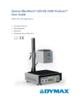
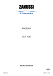
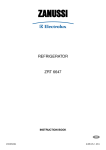
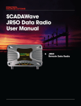
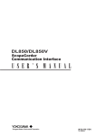
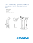
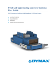
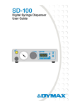
BlueWave® LED VisiCure™ User Guide LED Spot-Curing System ■ Instructions for Safe Use ■ Setup and Operation ■ Maintenance ■ Ordering Spare Parts and Accessories 2 Dymax BlueWave® LED VisiCure™ User Guide About Dymax UV/Visible light-curable adhesives. Systems for light curing, fluid dispensing, and fluid packaging. Dymax manufactures industrial adhesives, light-curable adhesives, epoxy resins, cyanoacrylates, and activator-cured adhesives. We also manufacture a complete line of manual fluid dispensing systems, automatic fluid dispensing systems, and light-curing systems. Light-curing systems include LED light sources, spot, flood, and conveyor systems designed for compatibility and high performance with Dymax adhesives. Dymax adhesives and light-curing systems optimize the speed of automated assembly, allow for 100% in-line inspection, and increase throughput. System designs enable stand-alone configuration or integration into your existing assembly line. Please note that most dispensing and curing system applications are unique. Dymax does not warrant the fitness of the product for the intended application. Any warranty applicable to the product, its application, and use is strictly limited to that contained in the Dymax standard Conditions of Sale. Dymax recommends that any intended application be evaluated and tested by the user to ensure that desired performance criteria are satisfied. Dymax is willing to assist users in their performance testing and evaluation by offering equipment trial rental and leasing programs to assist in such testing and evaluations. Data sheets are available for valve controllers or pressure pots upon request. Dymax BlueWave® LED VisiCure™ User Guide Contents Introduction .................................................................................................................................................... 4 Introduction to the User Guide ....................................................................................................................................... 4 Where to Get Help .......................................................................................................................................................... 4 Safety.............................................................................................................................................................. 4 Dymax UV Light-Curing System Safety Considerations ................................................................................................... 5 Product Overview ........................................................................................................................................... 7 Description of the BlueWave LED VisiCure ...................................................................................................................... 7 Intensity Control Feature ................................................................................................................................................ 7 Validation ........................................................................................................................................................................ 8 Assembly and Setup ........................................................................................................................................ 9 Unpacking and Inspecting Your Shipment ....................................................................................................................... 9 Parts Included in the BlueWave LED VisiCure Spot Lamp System ................................................................................... 9 Installation & System Interconnect ............................................................................................................................... 10 Operation ..................................................................................................................................................... 12 9-Pin Connector I/O Signals .......................................................................................................................... 13 Input Signals .................................................................................................................................................................. 13 Output Signals ............................................................................................................................................................... 14 Cleaning and Maintenance ........................................................................................................................... 16 Lightguide ...................................................................................................................................................................... 16 Fan Filter ........................................................................................................................................................................ 16 Fuse Replacement ......................................................................................................................................................... 16 Troubleshooting............................................................................................................................................ 17 Frequently Asked Questions ......................................................................................................................... 18 Spare Parts and Accessories .......................................................................................................................... 19 Options/Accessories ...................................................................................................................................................... 19 Spare/Replacement Parts .............................................................................................................................................. 19 Specifications ................................................................................................................................................ 20 Specifications................................................................................................................................................................. 20 Warranty ...................................................................................................................................................... 22 Index ............................................................................................................................................................. 23 3 4 Dymax BlueWave® LED VisiCure™ User Guide Introduction Introduction to the User Guide This guide describes how to assemble, use, and maintain the BlueWave® LED VisiCure™ spot-curing system safely and efficiently. Intended Audience Dymax prepared this user guide for experienced process engineers, technicians, and manufacturing personnel. If you are new to UV light curing and do not understand the instructions, contact Dymax Application Engineering to answer your questions before using the equipment. Where to Get Help Additional resources are available to ensure a trouble-free experience with our products: Detailed product information on www.dymax.com Customer Support and Application Engineering teams available by phone and email in the United States, Monday through Friday, from 8:00 a.m. to 5:30 p.m. Eastern Standard Time. You can also email Dymax at [email protected]. See the back cover for worldwide contact information. Dymax adhesive Product Data Sheets (PDS) on our website Material Safety Data Sheets (MSDS) provided with shipments of Dymax adhesives Safety Before continuing with the installation, please read the following chapters of this manual for safety recommendations and installation, operation, and troubleshooting instructions. CAUTION! Always wear protective goggles or face shield when working near the front of the unit, which emits high-intensity visible light! WARNING! CAUTION! Always observe safety requirements! Risk of electrical shock if cover is removed! To use a BlueWave LED VisiCure system safely, it must be set up and operated in accordance with the instructions given by Dymax. Using the system in any other manner will impair the protection of the system. Dymax assumes no liability for any changes that may impair the protection of the BlueWave LED VisiCure system. Safety Recommendations ■ Use the goggles provided or an approved face shield for eye/face protection. Dymax BlueWave® LED VisiCure™ User Guide ■ 5 Long-sleeved shirts or a lab coat are recommended for arm protection. The use of opaque gloves will protect the hands. NOTE: The BlueWave LED VisiCure emits high-intensity light. Never look directly at the light-emitting end of the lightguide while the unit power is on. Dymax Light-Curing System Safety Considerations Dymax light-curing technology has been used successfully for over 30 years. The fast cure, one-component nature of our curing technology has made it the process of choice for many manufacturers requiring a “Cure on Demand” assembly process. There are four common questions/concerns related to light-curing systems: UV exposure, high-temperature surfaces, ozone, and bright, visible light. NOTE: The energy emitted from the Dymax BlueWave LED VisiCure spot-curing system is in the Visible portion of the spectrum. To ensure that all safety aspects regarding operations of this equipment are addressed, please review and follow information and safety information listed below. Light Exposure Standard Dymax VisiCure systems have been designed to primarily emit visible light (as shown in Figure 1). Although OSHA does not currently regulate visible or ultraviolet-light exposure in the workplace, the American Conference of Governmental Industrial Hygienists (ACGIH) does recommend Threshold Limit Values (TLV’s) for ultraviolet light. The strictest interpretation of the TLV (over the UVA range) for workers’ eyes and skin is 1 2 mW/cm (intensity), continuous exposure. Unless workers are placing bare hands into the curing area, it is 2 unusual to exceed these limits. To put the 1 mW/cm limit into perspective, cloudless summer days in 2 Connecticut regularly exceed 3 mW/cm of UVA light, which includes the more dangerous UVB light, primarily responsible for sun tans, sun burns, and skin cancer. Figure 1. Light Spectrum Checking the Workstation A radiometer should be used to measure stray light to confirm the safety of a visible light-curing process. A 2 workstation that continuously exposes an operator to more than 1 mW/cm of UVA light should be redesigned. 6 Dymax BlueWave® LED VisiCure™ User Guide Protecting Operators Light-curing technology can be a regulatory compliant, "worker-friendly" manufacturing process when the proper safety equipment and operator training is utilized. There are two ways to protect operators from visible light exposure: shield the operator and/or shield the source. Shield the Operator Tinted eyewear will shield the operator from high intensity visible energy, and reduce eye fatigue. Shield the Source of the Light Any substrate that blocks Visible light can be used as a shield to protect workers from stray light. The following materials can be used to create simple shielding structures: Sheet Metal – Aluminum, steel, stainless steel, etc. Sheet metal should be coated black or black anodized to minimize reflection of UV and visible light toward operators. – Transparent or translucent/light-blocking plastics (typically polycarbonate or acrylic) are commonly used to create shielding where some level of transparency is also desired. Rigid Plastic Film – Translucent light-blocking, flexible urethane films can be used to quickly create workstation shielding. This light-blocking, flexible urethane film is available from Dymax. Call for assistance. Flexible Film High-Temperature Surfaces Surfaces exposed to high-intensity curing lights will rise in temperature. The intensity, distance, exposure time, cooling fans, and the type/color of the surface can all affect the actual rise in surface temperature. In some cases, exposed surfaces can reach temperatures capable of producing a burn or causing damage to a substrate. In these cases, care must be taken to ensure either a more moderate surface temperature or appropriate protection/training for operators. No infrared radiation is produced by these LED systems, so surface temperatures will be lower than with conventional lamp systems. Empirical testing should be used to verify the exact temperature rise in each application. Ozone The Dymax BlueWave LED VisiCure does not generate UVB or UVC, therefore no ozone is generated while operating this equipment. Bright, Visible Light The bright, visible light energy emitted by curing systems can cause eye strain if proper eye protection or shielding is not used. The proper use of tinted eye protection and/or opaque/tinted shielding can be utilized to reduce eye strain and address this concern. Summary Light sources can be more “worker friendly” than many commonly accepted industrial processes, provided the potential concerns are addressed. Both the lower working temperature and lack of spurious frequency transmission that this system produces make it even more user friendly. Contact your Dymax representative for information regarding the proper use of Dymax curing systems. Dymax BlueWave® LED VisiCure™ User Guide Product Overview Description of the BlueWave LED VisiCure The BlueWave LED VisiCure is a light-curing spot lamp that generates curing energy using high-intensity Light Emitting Diodes (LEDs). The relatively narrow frequency band produced by LEDs generates cooler curing temperatures and makes the BlueWave LED VisiCure an excellent choice for spot curing various coatings and adhesive bonding of polycarbonate, PVC, PET, metal, glass, and many other substrates. LED light-curing systems offer many advantages over conventional spot-curing systems including no bulbs to change, cooler cures, no warm-up, and constant intensity for thousands of hours. The BlueWave LED VisiCure is rated for continuous operation and can run in either timed or manual operating modes. The power supply operates on line voltages of 100 to 240 VAC, 50/60 Hz. The BlueWave LED VisiCure unit is comprised of an anodized aluminum housing which contains an electronic power supply, circuit protection, an LED assembly, cooling fans, a lightguide mount, a lightguide safety interlock, and a control PCB with connections for a remote operation system. Cooling fans are provided to keep the housing and internal components of the unit at the optimum operating temperature. The fan filter should be changed or cleaned frequently to prevent blockage and reduced ventilation airflow. The air vents must not be covered or otherwise blocked. A thermal shutdown sensor is provided for internal temperature control of the unit. The unit’s curing energy is emitted from a lightguide. This guide can be hand-held for complete mobility, positioned into a fixture for repetitive operations, or mounted to automated equipment. The lightguide is separate from the unit and plugs into the lightguide mount on the front panel of the unit. WARNING! Insert the lightguide into the lightguide mount before the light is turned on, and remove the lightguide ONLY AFTER the light is turned off. To secure the lightguide, lightly tighten the set screw (located on the top of the lightguide mount) after the lightguide is inserted. If the lightguide is removed at any time during an exposure cycle, the power is removed from the LED immediately. Replacing the lightguide will automatically re-energize the LED. The unit also features an intensity control on the front panel, which allows operators to adjust the output intensity during process validation and production. Users can adjust and maintain the output intensity level from 0 - 100% to meet their process curing parameters. Intensity Control Feature The components used in all curing systems degrade with use. Intensity, therefore, decreases as the system ages. The BlueWave LED VisiCure intensity control allows for compensation to address this slow degradation. Users can eliminate this variation by manually increasing output intensity to offset this degradation. The intensity can be adjusted with a tool, as shown in Figure 2. The intensity adjustment is a 10-turn potentiometer and allows fine control of output intensity. This feature is useful for both validation and control. 7 8 Dymax BlueWave® LED VisiCure™ User Guide Figure 2. Intensity Adjustment Validation Tests should be conducted prior to production to determine the time and light intensity required to fully cure your light-curable material in your specific application. The following approaches may be used to validate the curing process. Set Exposure Time, Determine Intensity Users can specify a cure time and, through empirical testing, determine the intensity required to achieve a full cure. As with any manufacturing process, it is advisable to incorporate a safety factor. Set Intensity, Determine Exposure Time Users can specify light intensity and, through empirical testing, determine the exposure time required to achieve a full cure. As with any manufacturing process, it is advisable to incorporate a safety factor. Control Process validation confirms a minimum acceptable intensity. Users can then choose to operate at a higher available intensity level (using the additional intensity as a cure safety factor) or adjust the output to a specific intensity level. To ensure consistent and repeatable process results, it is advisable to monitor intensity levels with the use of a radiometer. This allows identification of any potential maintenance requirements or intensity adjustment necessary. Dymax BlueWave® LED VisiCure™ User Guide Assembly and Setup Unpacking and Inspecting Your Shipment Your BlueWave LED VisiCure arrived in one or two boxes. Inspect the boxes for damage and notify the shipper of box damage immediately. Open each box and check for equipment damage. If parts are damaged, notify the shipper and submit a claim for the damaged parts. Contact Dymax so that new parts can be shipped to you immediately. Check that the parts included in your order match those listed below. If parts are missing, contact your local Dymax representative or Dymax Customer Support to resolve the problem. Parts Included in the BlueWave LED VisiCure Spot Lamp System ■ BlueWave LED VisiCure – Part Number Dependent on Power Cord Ordered (1) ■ Footswitch PN 40402 (2) ■ UV Protection Goggles PN 35285 (3) ■ 2-mm Hex Wrench PN 38656 (4) ■ Flat Blade Screwdriver PN 39695 (5) ■ BlueWave LED VisiCure User Guide PN 41065 (6) ■ Snap-In Clip PN 39667 ■ Filter Media PN 40008 ■ Power Cord (7) Model 41062– Standard 120V North American Power Cord Model 41063 – Type G Plug Model 41064 – No Power Cord (Note: For European customers, the appropriate power cord will be added) Figure 3. BlueWave LED VisiCure Components 9 10 Dymax BlueWave® LED VisiCure™ User Guide Installation & System Interconnect 1. Connect the Power Cord to the rear of the unit and plug into a grounded wall outlet. 2. Connect the Footswitch to the connection in the rear of the unit. Figure 4. Rear Panel Cable Connections 3. Install the Lightguide: ■ Remove the protective cover from the unit’s Lightguide Mount. ■ Remove the protective end caps from the Lightguide. ■ Visually inspect the two ends of the Lightguide to verify that no foreign material is present. NOTE: Dymax liquid-filled lightguide ends can be cleaned with isopropyl alcohol to remove foreign material and outgassing deposits. ■ Fully insert the large end of the Lightguide into the Lightguide Mount on the front panel. NOTE: When properly seated, a light “click” may be heard and/or felt. Figure 5. Lightguide Mount Set Screw If desired, the Lightguide may be fastened into place by lightly tightening the Securing Set Screw in the top of the Lightguide Mount. A Hex Wrench is provided with the unit for this purpose. The Set Screw should be tightened gently to prevent damaging the Lightguide. Dymax BlueWave® LED VisiCure™ User Guide 11 NOTE: Multi-pole lightguides should be checked for leg-to-leg output uniformity. Rotate the lightguide to verify the desired intensity of each leg before tightening the set screw. ■ The Lightguide is now installed and ready for use. The end of the Lightguide should be periodically cleaned with isopropyl alcohol. Adhesive build-up may be removed from the end of the Lightguide by gently scraping using a razor blade or razor knife. 4. Turn the Power Switch to the on position. 5. There is no need for a warm-up or cool-down period with this LED system. The unit may be powered down and powered up again immediately without causing any negative effects. 6. Activate an exposure cycle by pressing on the Footswitch. With the Timer/Manual Selector Switch (located on the front panel of the unit) in the manual position, the exposure time is controlled directly from the Footswitch. In the timed position, operation is determined by the setting displayed on the electronic timer. Simply push the timer setting buttons to enter the desired number of seconds the LED needs to be powered. 7. With the system exposure active, adjust the Intensity Adjustment Screw as required to achieve the desired output intensity on an appropriate radiometer. The Intensity Adjustment Screw is a 10- turn potentiometer. Figure 6. Intensity Adjustment Screw 12 Dymax BlueWave® LED VisiCure™ User Guide Operation The BlueWave LED VisiCure will arrive almost fully assembled. Please refer to the installation section of this manual for installation of the lightguide, power cord, and footswitch. The system should be positioned in a dry location that does not obstruct airflow around the unit. IMPORTANT: To ensure that exposure output of the system is obtained, be sure that the lightguide is fully inserted and seated into the entrance fitting prior to tightening the set screw. Be sure to lightly tighten the set screw to ensure the lightguide remains in place during use. To energize the system, turn the main power switch from the “O” position to the “l” position; the power supply and timer should begin to function. Figure 7. Main Power Switch Figure 8. Timer CAUTION! Always wear protective goggles or a face shield when working near UV or bright visible light. Never look directly at the light-emitting end of a lightguide. The timer located on the front panel of the BlueWave LED VisiCure is factory set to the most common operating mode and recommended operation of the timer with the BlueWave LED VisiCure. The front panel of the timer contains an LED display and keypad. The LED display has a reset indicator, keyprotect indicator, output indicator, preset value, set value, and timing operation indicator. A brief description of each display and location: Output Indicator – Displays OUT in upper left corner of timer display. Displayed when relay is switched on; is not displayed when relay is switched to off. Present Value – Four-digit segmented display in center of timer. Set Value – Four-digit segmented display in lower right corner of timer. Reset Indicator – Display on the left of meter face. Active when the timer is reset by pressing the Shows current status of time. Shows set length of time. “RST” button on the lower left face of timer. Or when the rear panel PLC Safety Interlock is active. “RST” can also be used to cancel a currently running exposure cycle Dymax BlueWave® LED VisiCure™ User Guide Key Protect – Located on center left side of display. Will always be lit because the timer function is programmed at the factory and locked before shipment. To operate the timer, select the “TIMER” option of the Timer/Manual Selector Switch on the front panel. In this mode, the LED will remain powered on until the timer counts down to 00.00. To program the Timer, press the appropriate key (up or down) until the corresponding digit increments or decrements in the set value. By pressing the up key labeled (1), it will increment the left most digit on the set value. By pressing the up key (2), it will increment the second digit of the set value. The same will happen with the up key (3) and the third digit of the set display, and up key (4) and the fourth digit of the set display. The Timer will increment from 9 back to 0. The Timer comes programmed for a range of 00.01 seconds to 99.99 seconds. Consult the factory for other time ranges and function options available. Program the time into the Timer and depress the Footswitch to activate the LED. Factory settings will power the LED and the programed value will begin to count backward. When the Timer reaches 00.00, it will reset to the programed value and remove power from the LED. The Timer can be stopped by pressing the RESET button on the lower left face of the Timer. If power is removed from unit, the Timer will reset to the programed value. There are a few fault conditions that may shut off the LED during operation. The LED will automatically shut off if the internal sensors reach an over-temperature condition. If an over-temperature shutdown occurs, check that the airflow is not restricted to the system and that the fan filter is clean. If the condition persists, consult Dymax Customer Service for further assistance. If the lightguide is not fully seated into the unit, or if it becomes dislodged by as little as ⅛" from the Lightguide Mount, the Safety Interlock Switch will terminate power to the LED. Re-seating the lightguide will automatically re-activate it. No user-serviceable parts exist within the enclosure. The LED does not employ an automatic life-end shutdown circuit. Position the curing end of the lightguide no closer than ¼" from material being cured. Placing the lightguide end too close can cause the lightguide to become cloudy from vapors coming off of the curing material. In a typical bulb-based system, lamp life is reduced each time it is started. The new LED-based systems have no such limitations. They can be shut off and then immediately restarted with no cool-down or warm-up periods or loss of system lifetime. 9-Pin Connector I/O Signals The BlueWave LED VisiCure unit is equipped with a 9-pin D-subminiature connector that provides interface between the device and a PLC or similar factory control equipment. The following describes available inputs and outputs. Input Signals Each input signal is optically isolated from the internal circuit of the BlueWave LED VisiCure. A positive +24V and maximum 10-milliamp current source is required to activate each signal input. All inputs are returned to the common terminal, and have built-in current-limiting resistors to protect the isolators. 13 14 Dymax BlueWave® LED VisiCure™ User Guide Pin 1 – +24V: Applying power to this pin enables the Safety Interlock (4). The safety interlock will not function unless +24V is applied to this pin. Pin 2 – Common: All signals, both inputs and outputs, are returned to this pin. Common may be used independently of +24V for all outputs and inputs, except for the safety interlock (4) input. Pin 3 – Shutter In: This signal line may be used to remotely activate the BlueWave LED VisiCure. When it is being used, the local footswitch on the rear of the BlueWave LED VisiCure box is still capable of operating the unit. Similar to the footswitch, if the timer/manual selector switch is in Timer Mode, the unit will power the LED for the time set on the timer. In the Manual Mode, the unit will power the LED for the duration of the remote activate signal. Pin 4 – Safety Interlock In: A safety interlock can be connected between Pins 1 and 4. While +24V is applied to Pin 4, the system will allow activation of the LED. If the connection is broken, power is immediately removed from the LED. The safety interlock relies on the +24V signal being present on Pin 1. In addition to removing power from the LED, if the system is being operated in the TIMED mode, breaking this connection will reset the timer to zero. A second “shutter” signal will reactivate the LED for the timed duration. Pin 5 – Intensity In (PWM): This input is supplied as a means to actively control the output intensity of the BlueWave LED VisiCure unit. It can be used to Pulse Width Modulate (PWM) the power to the LED. This input cannot increase the intensity over the set point of the front panel intensity adjustment, but can only reduce it. The front panel adjustment should be set fully clockwise to give Pin 5 the greatest range. A high level (+24V) on Pin 5 will turn off the LED and a low level (0V) will allow maximum LED intensity. A signal of 1.K Hz should be used with a duty cycle of 0 to 60%. NOTE: A 10% duty cycle will generate a greater intensity than a 50% duty cycle. This input can be used with an external controller to create any number of customized step-cure profiles or with an additional sensor to regulate the output. Output Signals The output signals are all opto-isolated signals. Each signal has an NPN output transistor. The emitters of all output transistors are tied together and connected to the PLC common on DB9 Pin 2. Each individual output signal line is connected to the collector of each transistor. When the transistor is turned on, this provides a ground to the PLC system that can be used to enable a relay coil signal to an opto-coupler. The conducting transistor can also function as a set of contacts that can initiate actions within the PLC. When the transistor is on, the signal is said to be “enabled” or “asserted”. When the transistor is off, the signal is said to be “disabled” or “unasserted”. The transistors have a max current rating of 30 mA, and a max power rating of 150 mW. Only positive voltages with respect to the PLC common should be used to a maximum of 24 Volts DC. Series-limiting resistors should be used to ensure that the max conditions are not exceeded. Pin 6 – Lightguide Engaged Out: When a lightguide is fully inserted into the unit, an internal switch will allow the LED to operate. The same switch will send a signal to turn on the transistor and connect Pin 6 to Pin 2. This output can be used to verify the condition of the system, should an error occur, or alert a user to the failure. Dymax BlueWave® LED VisiCure™ User Guide Pin 7 – LED Lit Out: Pin 7 will be shorted to Pin 2 when the LED is powered up and the set point is above a predetermined level. Pin 7 will be open with respect to Pin 2, if the LED is off for any reason. This output can be used as go/no go confirmation that the array is engaged. Pin 8 – Intensity Out (PWM): An internal circuit monitors the current sent to the LED, and generates a PWM signal whose frequency and duty cycle varies with the current. Adjusting the front panel Intensity Adjustment Screw, or using the Intensity Input on Pin 5, will cause a change in the signal seen on Pin 8. This output can be used to verify step or ramped changes in the intensity for customized profiles, or to alert the remote controller when the system has reached maximum intensity in a closed-loop system. Pin 9 – Over Temp Out: A sensor constantly monitors the temperature of the LED in the system. If, for any reason, the reading rises above a predetermined limit, the control PCB will shut off current to the LED to prevent damage. When the measured temperature drops to a lower threshold, the PCB will re-enable current to the LED. NOTE: If this fault occurs, check for proper airflow into and out of the unit. Also verify that the air filter is clean. Figure 9. 9-Pin D Connector I/O Signals 15 16 Dymax BlueWave® LED VisiCure™ User Guide Cleaning and Maintenance The BlueWave LED VisiCure was designed to operate with minimum maintenance. Follow the schedule below to assure top unit performance. Lightguide Clean the lightguide ends monthly or as required. The ends of the lightguide should be kept clean to transmit as much light as possible. Cured adhesive can be carefully removed from liquid-filled lightguide ends with a razor blade. Avoid sharp bends with the lightguide since this reduces light output and permanently damages the guide. Fan Filter The external fan filter should be inspected and cleaned periodically to prevent dust buildup from affecting airflow through the unit. Spare filters are provided with each unit. The fan filters are washable and may be reused. Remove the fan filter by removing the snap-on cover from the rear of the fan. Figure 10. Cooling Fan Figure 11. Cooling Fan Cover and Filter Fuse Replacement The unit is supplied with two Fuses that are installed in the Power Receptacle. To remove the Fuses, unplug the unit and remove the Fuse Holder with a small screwdriver. Remove the Fuses from the Fuse Holder and install new Fuses. Replace the Fuses with 2.0 Amp fast-blow types (Dymax PN 37236 or equivalent). Reinstall the Fuse Holder into the Power Receptacle. Figure 12. Power Receptacle Figure 13. Fuse Holder Figure 14. Fuses (PN 37236) Dymax BlueWave® LED VisiCure™ User Guide Troubleshooting WARNING: Only qualified maintenance personnel should attempt the following procedures. Table 1. Troubleshooting Chart for BlueWave LED VisiCure Problem Possible Cause Testing Corrective Action The unit’s LED will not illuminate There is an incorrect connection Visually inspect all input/output connections (i.e. power cord, foot switch, lightguide). Secure all connections. The main line fuse is blown (nothing in unit operates) Remove the fuse from the power receptacle and check it with an ohmmeter. Replace the fuse if defective. The lightguide is not fully inserted Remove the lightguide. Re-insert the lightguide into the lightguide mount. The intensity adjustment is set too low Use a radiometer (Dymax ACCUCAL 50-LED) to measure the output intensity. Adjust the setpoint to the desired intensity. The transmission loss in the lightguide is too great Compare the lightguide output against a new lightguide or use a Dymax lightguide simulator to determine the transmission loss. Replace the lightguide. There are contaminants on the lightguide Visually examine ends of lightguide for contaminants. Clean the lightguide ends with isopropyl alcohol or an equivalent. Heavy deposits on liquid lightguides may be carefully removed using a razor blade. Replace the lightguide if it cannot be cleaned. The system has inadequate cooling Check the air filter for debris and blockages at the exit vents. Clean or replace the filter. Remove all air blockages from around the unit. There is an incorrect connection Check the connection of the footswitch into the unit. Re-insert the footswitch into the unit. The unit has low output intensity or The unit fails to cure the material in the allotted time The footswitch is not operating 17 18 Dymax BlueWave® LED VisiCure™ User Guide Frequently Asked Questions Q.) My BlueWave LED VisiCure will not turn on. A. Check the power cord connection. B. Check the fuses located where the power cord plugs into the unit. Q.) The LED will not light, but the unit is powered up. A. Check that the lightguide is fully seated in the lightguide mount. B. Confirm that the intensity adjustment is not at the minimum setting. C. Check the condition of the signals on the DB9 connector (+24V, Safety Interlock, and Intensity Input) Q.) I have low intensity. A. The end of the lightguide may have a build-up of adhesive. Carefully remove any build-up with isopropyl alcohol or for heavier deposits gently scrape it with a razor blade. B. The condition of the lightguide can also affect the intensity. All lightguides degrade with time, but intensity will also drop if the lightguide is bent or compressed. The intensity reading from the lightguide should be compared to the intensity reading from a lightguide simulator to determine the efficiency. C. The intensity adjustment is set incorrectly. Turn the knob fully clockwise for the maximum intensity out. D. The connections or signals applied to the DB9 connector are incorrect. Verify that the safety and intensity input lines are not shutting down current to the LED. Q.) Why does my BlueWave LED VisiCure unit seem to run very hot? A. Replace the fan filter media on the intake fan (located on the back panel). This is your first line of defense against airborne dust and debris. This filter media and several spares are supplied with new units and should be changed regularly. B. Ideal operation of this equipment suggests at least 6 inches of clearance around the unit for proper ventilation. Also confirm that the intake fan is not feeding from the exhaust of other equipment. C. Confirm that the fan is operating. D. Your equipment may already be full of dust and debris, causing over heating of the unit’s internal electronics. NOTE: The internal fans do not activate until required. If the setting of the intensity output is low or if the ambient air temperature is lower than normal, the fans may not be active or they may take longer than usual to engage. Dymax BlueWave® LED VisiCure™ User Guide Spare Parts and Accessories Options/Accessories Item Part Number Personal Protection Equipment Protective Goggles — Green 35286 Protective Goggles — Gray (standard model included with unit) 35285 Face Shield 35186 Radiometer Dymax ACCU-CAL™ 50-LED Radiometer (spot) 40505 Lightguides Lightguide Simulator, 5 mm 38408 Liquid-D Lightguide, 5 mm x 1 M 5720 Liquid-D Lightguide, 5 mm x 1.5 M 5721 Liquid-D Lightguide, 8 mm x 1 M 5722 Miscellaneous 1-40009 Carry Case with Foam Inserts 1-40010 2-40011 1-40012 Spare/Replacement Parts Item Part Number Fuses Fuses: F2.0 amp 37236 Fan Fan 40034 Fan Assembly 40004 Fan Filter and Holder 5097 Fan Filter Media 40008 Footswitch and AC Power Cords Footswitch 40402 Power Cord, North American 35255 Power Cord, China Type G Plug 40542 Tools & Hardware 2 mm Hex Wrench 38656 Flat Blade Screwdriver 39695 Miscellaneous Rubber Feet 5039 19 20 Dymax BlueWave® LED VisiCure™ User Guide Specifications Specifications Property Part Numbers Specification 41062 North American Version (standard 120V plug) 41063 Asian Version (Type G plug) 41064* Unit without a power cord † Total 16.8 W/cm typical (400-450 nm) 15.0 W/cm typical ‡ (320-395 nm) 0.233 W/cm typical ‡ (280-320 nm) 0 mW/cm typical ‡ Intensity Output Visible UVA UVB Power Requirements Power Supply Temperature/Humidity Timer Activation I/O Port Signals (PLC Integration) Cooling Housing Dimensions Weight Unit Warranty Certifications * † ‡ 2 (280-450 nm) 2 2 2 100-240 V, 50/60 Hz, <100 Watts Solid state, 100 Watt 40°C maximum/non-condensing Digital timer up to 99.99 seconds; manual or timed exposure Footswitch or PLC 9-Pin D – sub-miniature connector Inputs: +24VDC, activate, safety interlock, output adjust Outputs: LED lit, lightguide inserted, output setpoint, over temperature Filtered fan arrangement 5.4" x 8.5" x 8.8" [13.7 cm x 21.6 cm x 22.3 cm] 5.40 lbs. (2.45 kg) 1 year from purchase date CE marked Contains the appropriate power cord for Europe Measured with an ACCU-CAL™ 50-LED radiometer attached at the end of a Lightguide Simulator Measured with a UV Power Puck® II at the end of a Lightguide Simulator Figure 15. BlueWave LED VisiCure Spectral Output Dymax BlueWave® LED VisiCure™ User Guide 21 Definition of Terms Light Emitting Diode (LED) – A solid-state, semi-conducting device that generates a specific, narrow-band wavelength of energy. Intensity, also known as Irradiance 2 – A measure of energy over the unit of surface area (measured in 2 W/cm or mW/cm ). Brightness, also known as Luminance – A description of energy in the visible region of the spectrum (approximately 400-700 nm). Brightness is recorded in photometric units. The “Intensity” (see below) of visible light energy is called Illuminance. Illuminance – Luminous flux (energy of visible light) incident per unit area. Illuminance is measured in Lx (lux) or 2 Lumen/cm . Ultraviolet (UV) – The invisible region of the spectrum just beyond the violet end of the visible region. Wavelength ranges in general from 1-400 nm. Dymax bulbs (burners) do not radiate energy in deep Ultraviolet; there are very minute amounts below 220 nm and practically nothing can be sensed below 200 nm. This is due to the use of an ozone-blocking quartz bulb envelope (See Ozone). 1. Ultraviolet A (UV-A) – UV of long wavelength from within approximately 400 to 320 nm of the spectral band. 2. Ultraviolet B (UV-B) – UV of medium wavelength from within approximately 320-280 nm. 3. Ultraviolet C (UV-C) – UV of short wavelength below 280 nm (typically 280-200 nm) – a large amount of this energy is present in sunlight. 4. Visible – Light that can be seen at 400-700 nm. Dose 2 2 – Irradiance integrated over time, or Irradiance (W/cm ) x Time (s) = Dose (Joules/cm ). Note: Watt is the power that gives rise to the production of energy at the rate of 1-joule (J) per second (s). Ozone – An oxidizing agent (O3) produced by the action of Ultraviolet radiant energy (below 185 nm) or electrical corona discharge of oxygen on air. OSHA 1910.145: “Regulation of Accident prevention Signs and Tags” defines the following headers as: ■ WARNING – Used when there is a hazardous situation that has some probability of severe injury. ■ CAUTION – Used to indicate a hazardous situation that may result in minor or moderate injury. ■ NOTICE – Used to convey a message related directly or indirectly to the safety of personnel or protection of property. 22 Dymax BlueWave® LED VisiCure™ User Guide Warranty From date of purchase, Dymax Corporation offers a one-year warranty against defects in material and workmanship on all system components (excluding bulbs, LEDs, and Lightguides) with proof of purchase and purchase date. Unauthorized repair, modification, or improper use of equipment may void your warranty benefits. The use of aftermarket replacement parts not supplied or approved by Dymax Corporation, will void any effective warranties and may result in damage to the equipment. IMPORTANT NOTE: DYMAX CORPORATION RESERVES THE RIGHT TO INVALIDATE ANY WARRANTIES, EXPRESSED OR IMPLIED, DUE TO ANY REPAIRS PERFORMED OR ATTEMPTED ON DYMAX EQUIPMENT WITHOUT WRITTEN AUTHORIZATION FROM DYMAX. THOSE CORRECTIVE ACTIONS LISTED ABOVE ARE LIMITED TO THIS AUTHORIZATION. Dymax BlueWave® LED VisiCure™ User Guide Index Assembly and Setup, 9 Parts Included, 9 Cable Connections, 10 Product Overview, 7 Cleaning, 16 Safety, 4 Contact Information, 4 Safety of UV Light Bright Visible Light, 6 High-Temperature Surfaces, 6 Ozone, 6 UV Exposure, 5 Curing System Safety, 5 Definition of Terms, 21 Frequently Asked Questions, 18 Front Panel Timer, 12 Fuses, 16 Help, 4 I/O Signals, 13 Intensity Control Feature, 7 Maintenance, 16 Fan Filter, 16 Fuse Replacemet, 16 Lightguide, 16 Spare Parts and Accessories, 19 Specifications, 20 Support, 4 System Connections, 10 Troubleshooting, 17 Unpacking, 9 UV Exposure, 5 UV Light Shielding, 6 Operation, 12 Validation, 8 Optional Equipment, 19 Warranty, 22 23 In addition to our light-curing equipment, Dymax also offers high-performance oligomers, adhesives, and coatings as well as a variety of dispensing equipment. Our products are perfectly matched to work seamlessly with each other, providing design engineers with tools to dramatically improve manufacturing efficiency and reduce costs. Dymax is committed to providing the best chemistry, curing equipment, and dispensing systems that offer customers complete manufacturing solutions for their challenging applications. © 2013 Dymax Corporation. All rights reserved. All trademarks in this guide, except where noted, are the property of, or used under license by Dymax Corporation, U.S.A. Please note that most dispensing and curing system applications are unique. Dymax does not warrant the fitness of the product for the intended application. Any warranty applicable to the product, its application and use is strictly limited to that contained in Dymax’s standard Conditions of Sale. Dymax recommends that any intended application be evaluated and tested by the user to ensure that desired performance criteria are satisfied. Dymax is willing to assist users in their performance testing and evaluation by offering equipment trial rental and leasing programs to assist in such testing and evaluations. Data sheets are available for valve controllers or pressure pots upon request. PN41065 MAN056 5/21/2013 Dymax Corporation 860.482.1010 [email protected] www.dymax.com Dymax Oligomers &Coatings 860.626.7006 oligomers&[email protected] www.dymax-oc.com Dymax Europe GmbH +49 (0) 611.962.7900 [email protected] www.dymax.de Dymax UV Adhesives & Equipment (Shenzhen) Co Ltd +86.755.83485759 [email protected] www.dymax.com.cn Dymax UV Adhesives & Equipment (Shanghai) Co Ltd +86.21.37285759 [email protected] www.dymax.com.cn Dymax Asia (H.K.) Limited +852.2460.7038 [email protected] www.dymax.com.cn Dymax Korea LLC 82.2.784.3434 [email protected] www.dymax.co.kr