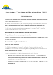
1
UVCS Version 2.0 For use with Dymax Flood Lamps UVCS UV Light-Curing Conveyor System (Shown with Two Dymax 5000-EC Lamps) Operation Manual TABLE OF CONTENTS Unpacking and Inspection .............................................................................................................. Page 3 Safety ·····················································································································Page 4-5 General Information ···································································································Page 6 System Components Description ··················································································Page 7 Specifications ···········································································································Page 8-11 Lamp Configurations ··································································································Page 12 Lamp Installation and Interconnect ················································································Page 13 Conveyor Operation ···································································································Page 14-15 Maintenance ············································································································Page 16-18 Troubleshooting ········································································································Page 19-20 Spare Parts & Accessories ··························································································Page 21 Definition of Terms ····································································································Page 22 Warranty ·················································································································Page 23 2 UVCS UV Light-Curing Conveyor System Version 2.0 The Dymax UVCS UV Light-Curing Conveyor System was developed and manufactured by the Dymax engineering team. Before shipping, your conveyor system was tested to ensure peak operating performance. The proper set up and operation of this Conveyor System will maximize safety and user-friendly integration, providing optimum yield and productivity. THEREFORE, WE ENCOURAGE YOU TO READ, UNDERSTAND, AND FOLLOW ALL SAFETY AND OPERATING INSTRUCTIONS AND RECOMMENDATIONS COMPILED IN THIS AND OTHER RELATED MANUALS prior to setting up and operating this new system or its individual components. If you encounter a problem, have any questions, or would like to provide suggestions or recommendations, please contact Dymax Applications Engineering or Customer Service. UNPACKING AND INSPECTION Upon receipt of the unit, carefully remove the contents from the boxes and check for damage. Dymax is not responsible for damage from shipping – all claims for shipping damage should be made with the carrier. Check all boxes for contents and write down any serial numbers for further reference. You may wish to retain the original shipping cartons in case you need to repackage any item for return. If you observe or experience any problem with your equipment, notify Dymax Customer Service, your authorized distributor, or your Dymax representative immediately. System Includes: UVCS Conveyor Unit Lamp and Power Source Two Pairs UV Goggles Operation Manual NOTE: REPORT ANY SHORTAGE TO DYMAX CORPORATION CUSTOMER SERVICE. Before continuing with unpacking and installation, please read the following chapters of this manual for safety recommendations and installation, operation, and troubleshooting instructions. UVCS UV Light-Curing Conveyor System Version 2.0 3 SAFETY Dymax ultraviolet light-curing technology has been used successfully for over 30 years. The fast cure, one component nature of our UV light-curing technology has made it the process of choice for many manufacturers requiring a "cure-on-demand" assembly process. There are four common questions/concerns related to UV lightcuring systems: UV exposure, high-temperature surfaces, ozone, and bright, visible light. UV EXPOSURE Standard Dymax UV light-curing systems and bulbs have been designed to primarily emit UVA light (Chart 1). UVA light is generally considered the safest of the three UV ranges: UVA, UVB, and UVC. Although OSHA does not currently regulate ultraviolet light exposure in the workplace, the American Conference of Governmental Industrial Hygienists (ACGIH) does recommend Threshold Limit Values (TLVs) for ultraviolet light. The strictest 2 interpretation of the TLV (over the UVA range) for workers’ eyes and skin is 1 mW/cm (intensity), continuous exposure. Unless workers are placing bare hands into the curing area, it is unusual to exceed these limits. To put 2 2 1 mW/cm limit into perspective, cloudless summer days in Connecticut regularly exceed 3 mW/cm of UVA light and also include the more dangerous UVB light (primarily responsible for sun tans, sun burns, and skin cancer) as well. Chart 1. Spectrum of Light The human eye can not detect “pure” UV light, only visible light. A radiometer should be used to measure stray UV light to confirm the safety of a UV curing process. A workstation that exposes an operator to more than 2 1 mW/cm of UVA continuously should be redesigned. UV adhesive curing can be a regulatory compliant, “worker-friendly” manufacturing process when the proper safety equipment and operator training is utilized. There are two ways to protect operators from UV exposure: shield the operator and/or shield the source. SHIELD THE OPERATOR UV-Blocking Eye Protection – UV-blocking eye protection is recommended when operating UV light-curing systems. Both clear and tinted UV-blocking eye protection is available from Dymax. UV-Blocking Skin Protection – Where the potential exists for UV exposure upon skin, opaque, UVblocking clothing, gloves, and full-face shields are recommended. SHIELD THE SOURCE OF UV Any substrate that blocks UV light can be used as a shield to protect workers from stray UV light. The following materials can be used to create simple shielding structures or blind corners: 4 Sheet Metal – Aluminum, steel, stainless steel, etc. Sheet metal should be coated black or black anodized to minimize reflection of UV and visible light toward operators. UVCS UV Light-Curing Conveyor System Version 2.0 Rigid Plastic Film - Transparent, UV-blocking plastics (typically polycarbonate or acrylic) are commonly used to create shielding where transparency is also desired. These rigid plastic films are available either water-clear or tinted. Flexible Film - UV-blocking, flexible urethane films can be used to quickly create workstation shielding. This UV-blocking, flexible urethane film is available from Dymax. HIGH-TEMPERATURE SURFACES Surfaces exposed to high-intensity UV light will rise in temperature. The intensity, distance, exposure time, cooling fans, and the type/color of the surface can all affect the actual surface temperature. In some cases, exposed surfaces can reach temperatures capable of producing a burn or causing damage to a substrate. In these cases, care must be taken to ensure either a more moderate surface temperature or appropriate protection and training for operators. OZONE Standard Dymax bulbs (UVA type) generate an insignificant amount of UVC and therefore essentially no ozone. Some UV light-curing systems, like those used to cure UV-curable inks, emit primarily “shortwave” (UVB and UVC) energy. Upon exposure to UVC light (specifically <240 nm), oxygen molecules (O 2) split into oxygen atoms (O) and recombine with O2 to create ozone O3. The current, long-term ozone concentration limit recommended 3 by ACGIH, NIOSH, and OSHA is 0.1 ppm (0.2mg/m ). BRIGHT, VISIBLE LIGHT The bright, visible light emitted by some UV light-curing systems can be objectionable to some workers and can cause eyestrain. Tinted eye protection and/or opaque/tinted shielding can be utilized to address this concern. SUMMARY UV light sources can be more “worker friendly” than many commonly accepted industrial processes, provided the potential concerns are addressed. Contact your Dymax representative for information regarding the proper use of Dymax UV light-curing systems. UVCS UV Light-Curing Conveyor System Version 2.0 5 GENERAL INFORMATION The Dymax UVCS UV Light-Curing Conveyor System is designed to provide reliable and consistent processing of UV-reactive adhesives and coatings. The conveyor is available in a 120 volt or a 200-240 volt model. Dymax 5000-EC, 2000-EC, and 1200-EC Flood Lamp Systems are auto voltage select. The Conveyor's standard features include a Direct Drive Motor, an integrated adjustable Cooling System, and a UV-Resistant Belt. The UVCS is designed for bench- or table-top operations. The self-contained Cooling System and integral UVLight Shielding allow it to be placed virtually anywhere space permits. Dymax UV light sources are capable of curing a wide variety of UV-curable adhesives, coatings, and inks. They have extensive use in a variety of applications such as bonding, potting, sealing, and encapsulating. These light sources offer exceptional versatility and expandability to accommodate most process demands. A large number of accessories are available for the base Conveyor. These items address safety, as well as functional flexibility, which is depicted and discussed in this manual. Figure 1. UVCS Light-Curing Conveyor System (shown with two 5000-EC Lamps) 6 UVCS UV Light-Curing Conveyor System Version 2.0 SYSTEM COMPONENTS DESCRIPTION 1200-EC The Dymax 1200-EC is a focused-beam UV Lamp used for the curing of UV light-curable adhesives, coatings, and inks. The unit's elliptical Reflector provides an intense 1" x 6" area of UV energy, 4.5" away from the lower edge of the Lamp/Reflector Assembly Housing. The 1200-EC employs convection cooling. An optional Fan Ventilation Kit is available. This kit removes excessive heat and ventilates curing vapors away from the Lamp/Reflector Assembly Housing. Refer to the spare parts/options section of this manual for more information on the Fan Ventilation Kit. Figure 2. 1200-EC Lamp & Power Supply 2000-EC The Dymax 2000-EC is a general purpose UV Flood Lamp with an effective curing area of approximately 8" x 8", making it ideal for batch processing or curing large areas. An optional Glass UV Filter may be installed in the 2000-EC Reflector to reduce UV-B and UV-C spectral emissions. When operated correctly using the Glass UV Filter, extensive shielding associated with many Lamps can be minimized. The 2000-EC employs convection cooling. An optional Fan Ventilation Kit is available. This kit removes excessive heat due to the Lamp’s possible proximity to other heat sources and removes vapors from under the Lamp/Reflector Assembly Housing during curing of UV light-curable materials. Refer to the spare parts/options section of this manual for more information on the Fan Ventilation Kit. Figure 3. 2000-EC Lamp & Power Supply 5000-EC The Dymax 5000-EC is a general purpose UV Flood Lamp with an effective curing area of approximately 5" x 5". The unit is ideal for small batch processing of UV-curable adhesives and potting compounds. The 5000-EC provides more than twice the output intensity of a 2000-EC Flood Lamp, allowing for faster curing capability and the additional ability to cure conformal coating resins. UVCS UV Light-Curing Conveyor System Version 2.0 Figure 4. 5000-EC Lamp & Power Supply 7 SPECIFICATIONS GENERAL A solid-state Lamp Power Supply that allows external electrical inputs and provides power to the Lamp located in the Lamp/Reflector Assembly Housing. The Power Supply contains the On/Off Power Switch and Hour Meter that are located on the left side of the front panel. The Power Supply also houses its own Cooling Fans and power distribution for optional accessories. The rear panel has an integrally fused AC Power Receptacle, and a 14-Pin Female Amp Connector. The Solid-State Lamp Power Supply yields reliable and stabilized Lamp voltage in virtually any electrical system in the world. No other adjustment or settings are required other than ensuring a properly wire configured plug is employed to the system. The Power Supply also conditions the electrical power to the Lamp providing longer, more reliable Lamp life. A Lamp/Reflector Assembly Housing (refer to drawing on specific models in flood lamp manual) which contains the Reflector, Bulb, Lamp Bases, high-voltage Starter, and three circular Connectors. Connection Cable between the Power Supply and Lamp/Reflector Assembly Housing. An AC Input Power Cord. 400 Watt Metal Halide UV Lamp; optional Mercury Vapor (PN 36970), or Visible Spectrum Lamps (PN 36658) are available upon request. Figure 5. UVCS Conveyor Dimensions 8 UVCS UV Light-Curing Conveyor System Version 2.0 GENERAL SPECIFICATIONS: Table 1. Electrical Specifications Voltage Requirements 115 or 220 VAC, 50 or 60 HZ Current Requirements Defined in Table # 3 Lamp/Power Supply Input Voltage 100-240 VAC (continuous) Dymax Lamp systems Input Current Defined in Table # 5 for individual model numbers Conveyor and Lamps Total Input Current Defined by Table # 4 Table 2. Physical Specifications Model Cure Width UVCS Version 2.0 6" - 12" [152 - 305 mm] Lamp Configurations Single Dymax 1200-EC Single Dymax 2000-EC Up to four Dymax 5000-EC Motor Drive Direct Belt Speed 0.8 - 32.0 FPM [.304 - 9.73 m/min.] Belt Speed Display Red LED, 1 decimal place Lamp Focus Adjustment 2.1" - 4.5" [53.3 mm - 114 mm] Maximum Part Height 4.5" [114 mm]* Exhaust System 1 Integral Centrifugal Blower * Larger part heights are achievable with the installation of optional riser kits. The UVCS-Series Conveyor has a 12" belt width. Different Lamp installations can use between 6" and 12" of that belt width. Table 3 defines the descriptive nomenclature which makes up the part number. Table 3. Model Number Nomenclature Conveyor Model Lamp Mfg. Lamp Model Lamp Quantity Voltage 1-4 100 through 240 1 (1200-EC) UVCS D (Dymax) 2 (2000-EC) 5 (5000-EC) Legend: UVCS – D – 2 – 1 – 120 Voltage Lamp Quantity Lamp Model (5 = 5000 series, 2 = 2000 series, 1= 1200 series) Lamp Manufacturer (D = Dymax, 0 = No Lamps) Model Number UVCS UV Light-Curing Conveyor System Version 2.0 9 There are 12 known distinct model numbers (not including special configurations) that contain Dymax Lamps and 2 model numbers containing Zero Lamps. Table 3 indicates what components are used in each model. Table 4. Conveyor Configurations 5000 -EC Lamp Quantity Item 1 2* 3 4 5 6* 7 8 9 10 11 12 13 14 1 Model Number UVCS-D-5-1-120 UVCS-D-5-2A-120 UVCS-D-5-2B-120 UVCS-D-5-4-120 UVCS-D-5-1-220 UVCS-D-5-2A-230 UVCS-D-5-2B-230 UVCS-D-5-4-230 UVCS-D-2-1-120 UVCS-D-2-1-230 UVCS-D-1-1-120 UVCS-D-1-1-230 UVCS-0-0-120 UVCS-0-0-230 Part Number 39060 39070 39080 39100 39065 39075 39085 39105 39250 39135 39140 39145 39290 39291 2 4 2000-EC 1200-EC 1 1 v v v v v v v v v v v v *When two (2) Dymax 5000’s are used, specify whether in-line (2A) or side-by-side (2B) configuration Table 5. Conveyor AC Current Values (Start/Run Current) Reading At 115 VAC 50/60 Hz At 200-230 VAC 50/60 Hz Total Conveyor 4.8 A / 2.4A rms 2.4 A / 1.2 A rms Fan 2.0 A rms 1.0 A rms Motor Control 400mA rms 200mA rms Freq. Counter Not measurable Not measurable Table 6. UVCS Conveyor System Lamp System AC Current Requirements Lamp System AC Current at 115 VAC AC Current at 220 VAC Max Quantity on Conveyor Dymax 5000-EC 6.3A 3.15A 4 Dymax 2000-EC 6.3A 3.15A 1 Dymax 1200-EC 6.3A 3.15A 1 10 UVCS UV Light-Curing Conveyor System Version 2.0 Table 7. Total Current (Conveyor and Lamps) Item Model Number 1 2 3 4 5 6 7 8 9 10 11 12 UVCS-D-5-1-120 UVCS-D-5-2A-120 UVCS-D-5-2B-120 UVCS-D-5-4-120 UVCS-D-5-1-230 UVCS-D-5-2A-230 UVCS-D-5-2B-230 UVCS-D-5-4-230 UVCS-D-2-1-120 UVCS-D-2-1-230 UVCS-D-1-1-230 UVCS-D-1-1-230 UVCS UV Light-Curing Conveyor System Version 2.0 Total Conveyor and Lamp Current 8.7 A 15.0 A 15.0 A 27.6 A 4.4 A 7.5 A 7.5 A 13.8 A 8.7 A 4.4 A 8.7 A 4.4 A 11 LAMP CONFIGURATIONS DYMAX 1200-EC/2000-EC LAMPS Conveyors with Dymax 1200-EC or 2000-EC Lamps are single-Lamp configuration only (Figure 6). DYMAX 5000-EC LAMPS Conveyors with Dymax 5000-EC Flood Lamps may be configured in a one-Lamp (Figure 7), two-Lamp (Figure 8), or four-Lamp (Figure 9) configuration. Dual-Lamp configurations can be set up in-line for 6" wide curing (2A) or side-by-side for 12" wide curing (2B). Spacers and Block-Off Plates cover the unused Lamp locations. Additional Lamps can be purchased and added to existing UVCS Conveyor Systems. Figure 6. Single 1200-EC/2000-EC Configuration Models: UVCS-D1-1-120 & UVCS-D1-1-230 (1200-EC) UVCS-D2-1-120 & UVCS-D2-1-230 (2000-EC) Figure 8. Dual 5000-EC Configuration (2A Shown) Models: UVCS-D5-2A-120, UVCS-D5-2B-120, UVCS-D5-2A-230, & UVCS-D5-2B-230 12 Figure 7. Single 5000-EC Configuration Models: UVCS-D5-1-120 & UVCS-D5-1-230 Figure 9. Four 5000-EC Configuration Models: UVCS-D5-4-120 & UVCS-D5-4-230 UVCS UV Light-Curing Conveyor System Version 2.0 LAMP INSTALLATION AND INTERCONNECT 1. If purchased, uncrate and assemble the optional Conveyor Mounting Cart (Figure 10) prior to unpacking the Conveyor. 2. Remove the protective coverings from the Conveyor. Place the Conveyor on the Conveyor Mounting Cart or on a convenient work surface. Install the Exhaust Ventilation Stack on the Blower Motor’s Outlet Flange. Secure the Exhaust Ventilation Stack with the 3 fasteners provided (Figure 11). 3. Unpack the Lamp(s) (a single 1200-EC or 2000-EC Lamp or up four 5000-EC Lamps). Each Flood Lamp System includes a Power Supply, Reflector Assembly, 400 Watt Bulb, Lamp Connector Cord, and a Power Cord. (Figure 12) Figure 10. Optional Mounting Cart Figure 11. Secure Exhaust Ventilation Stack Figure 12. Unpack Lamp (5000-EC Shown) 4. Install the Bulb into the Reflector Housing ensuring that the Bulb is properly seated (Figure 13). Consult the Flood Lamp System manual for details on installing Bulbs. 5. Attach the Lamp Connector Cord to the back of each Reflector (Figure 14). 6. Install the Reflector Assemblies into the Conveyor’s Upper Lamp Support Brackets (Figures 15 & 16). Adjust the position of the Lamps and tighten the four Lamp Securing Knobs. Configuration 2A (lamps in-line) and 2B (lamps side-by-side) are shown below (Figures 15 & 16). Up to four Lamps may be mounted into the Support Bracket. Figure 13. Install Bulb in Reflector Housing Figure 14. Attach the Lamp Connector Cord Figure 15. 2A Configuration Figure 16. 2B Configuration 7. Attach the Lamp Connector Cable leading from each Reflector to the rear of each Power Supply (Figure 17). Connect the Conveyor Power Cord to a 110-120V AC power source (200-230V AC for 230V units). Connect each Power Supply’s Power Cord to a 100-240V AC power source. Figure 17. Attach Lamp Connector Cable to Power Supply UVCS UV Light-Curing Conveyor System Version 2.0 13 OPERATION 1. Install all safety accessories to protect operator from UV-light emissions. 2. Apply power to the UVCS Conveyor and turn it on. 3. Unlock the Speed Control Knob (Figure 18) and adjust the Conveyor's speed for the desired setting. The Speed Control Knob is a 10-Turn Potentiometer and allows speed adjustment from approximately 0.8 FPM to 32 FPM (feet per minute). The speed is shown on the Belt Speed Indicator Display on the Conveyor's Control Panel (Figure 19). Figure 18. Speed Control Knob Figure 19. Conveyor Control Panel with Belt Speed Indicator Display 4. If any adjustments are needed for the Belt alignment, refer to the Maintenance Section of this manual. 5. Adjust the height of the Lamps to the desired distance (Figures 20-22). Height is adjustable from 2.1 inches to 4.5 inches. Figure 20-22. Lamps Adjusted to Various Heights 6. Once the speed and lamp height settings have been properly set, the Conveyor is ready for operation of the Lamps. NOTE: The Conveyor must be operating and the Conveyor Belt must be in motion before the Lamp(s) is turned on. This prevents Belt overheating and damage that can result if the Belt is stationary when the Lamp(s) is running. 7. Apply power to the UVCS Lamps and turn them on. 8. The Blower controls the amount of cooling air provided to the Lamp Assemblies to keep them at proper operating temperatures. A small percentage of the cooling air is also diverted downward through the Conveyor Belt. This air flow provides a small hold-down force to keep light objects from moving while traveling on the Belt. The speed of the Exhaust Blower is set at the factory during final system testing for the Conveyor model ordered. 14 UVCS UV Light-Curing Conveyor System Version 2.0 9. If the speed of the Exhaust Blower requires adjustment, remove the Access Panel from the front of the Exhaust Blower Housing (Figure 23). Unlock the Blower Speed Control Potentiometer (Figure 24) and adjust the speed setting. Relock the Blower Speed Control Potentiometer. The range of the Blower Speed Control Potentiometer is 0.0 to 0.85 turns. Table 8 shows the approximate settings for the speed of the Exhaust Blower. For 5000-EC Flood Lamps, a Temperature Indicator Strip (Temperature Strip Indicator Kit PN 38693) is attached to the Reflector Housing. Figure 26 shows a typical Temperature Indicator Strip reading a representative temperature. The optimum operating temperature is from 115°F to 145°F. Figure 23. Remove Access Panel Figure 24. Blower Speed Control Figure 25. Blower Speed Control (Close Up) Table 8. Blower Speed Potentiometer and UV Curtain Height Settings for Optimum Bulb Cooling Model Number Blower Potentiometer Setting Lamp Height 1" 3" 4.5" UVCS-D-5-1-120/230 0.0 0.27 0.45 UVCS-D-5-2A/2B-120/230 0.15 0.35 0.45 UVCS-D-5-4-120/230 0.45 0.54 0.80 C 30 35 40 45 50 55 60 C F 86 95 104 113 122 131 140 F Figure 26. Temperature Indicator Strip (PN 38693) for the Dymax 5000-EC Flood Lamps 10. The Conveyor is ready for operation. UVCS UV Light-Curing Conveyor System Version 2.0 15 MAINTENANCE BELT TRACKING ADJUSTMENT All Dymax UVCS Conveyors are factory adjusted to provide proper tracking of the Belt. Should further adjustments become necessary, this is done via the two knurled Tracking Adjustment Knobs located at the input end of the Conveyor. To adjust the Belt tracking, simply tighten the side to which the Belt is tracking. NOTE: Do not over tighten the Belt. This will lead to accelerated degradation of the Belt. Figure 27. Tracking Adjustment Knob BELT REPLACEMENT 1. Remove the Pinch Guard from the motor side of the Conveyor by removing the two M4x8 Screws (Figure 28) on the front side of the Conveyor and the M4x25 Screw (Figure 30) from the motor drive side of the Conveyor. Remove the Motor Box Cover (Figure 29) to obtain access to the M4x25 Screw. Figure 28. Remove M4x8 Screw Figure 29. Remove Motor Box Cover Figure 30. Remove M4x25 Screw Figure 31. Pinch Guard Removed 2. Remove all tension from the belt by fully backing off the Belt Adjustment Knobs (Figures 32-34). Figure 32-34. Back Off the Belt Adjustment Knob 16 UVCS UV Light-Curing Conveyor System Version 2.0 3. Position the Belt splice to the end of the Conveyor (Figure 35). Remove the Fiberglass Rod that ties the ends of the Belt together (Figure 36). Remove the Belt. 4. Run the new Belt around the Conveyor Frame (Figure 37). 5. Install the Fiberglass Rod through the Belt loops. 6. Apply some adhesive to both ends of the Fiberglass Rod to prevent it from moving during Conveyor operation (Figure 38). Figure 35. Place Splice at the End of the Conveyor Figure 36. Remove Fiberglass Rod Figure 37. Run New Belt Around Conveyor Frame Figure 38. Apply Adhesive to Fiberglass Rod 7. Tighten the Belt Tension Knobs (Figure 39) finger tight to remove excess slack from the Belt. The Belt should be loose enough to be moved across the two Rollers by hand when the Conveyor is not running. CAUTION: Excessive tightening of the Belt will result in early Belt failure. Since the two Conveyor Rollers have a crown in the middle, only minimum tightening is necessary. Figure 39. Tighten Belt Tension Knob Figure 40. Stopping Belt by Hand 8. Start the Conveyor and adjust the Belt Tensioning Knobs until the Belt runs in the center of the loading end. The Belt should be able to be stopped by hand when the Conveyor is running (Figure 40). If stopping the Belt stalls the Conveyor Motor, the Belt is too tight and must be loosened. UVCS UV Light-Curing Conveyor System Version 2.0 17 9. When the Belt runs in the center of the loading end, observe the Belt position at the Motor End. If the Belt runs too far to one side on the Motor end, adjust the Motor Pulley as follows: a. Turn the Conveyor off. b. Remove the Belt tension by loosening the two Belt Tensioning Knobs. c. Loosen the two Drive Roller Shaft Support Fasteners located on the front of the Conveyor Frame enough to slightly move the Shaft Assembly (Figures 41 & 42). Figure 41 & 42. Remove Drive Roller Shaft Support Fasteners d. Move the Shaft Assembly slightly to realign the Drive Roller and center the Belt (Figure 43). Tighten the bolts when adjustment is complete (Figure 44). Figure 43. Move Shaft Assembly to Center Belt Figure 44. Tighten Bolts e. Turn the Conveyor on and adjust the Belt Tension Knobs until the Belt is properly tightened. Make sure that the Belt runs in the center of the Conveyor on both the loading and unloading end. Repeat this step as necessary to align the Belt. f. Reinstall the Pinch Guards on both ends of the Conveyor (Figures 45 & 46). This step is critical to Belt Speed Sensor operation. The Pinch Guard on the unloading side of the Conveyor contains a Shield for the Sensor to prevent damage if the Belt contacts it while operating. Figure 45. Reinstall Pinch Guard 18 Figure 46. Reinstall Pinch Guard UVCS UV Light-Curing Conveyor System Version 2.0 TROUBLESHOOTING NOTE: Only qualified maintenance personnel should attempt the following procedures. CONVEYOR TROUBLESHOOTING Problem Conveyor Not Operating Possible Cause Testing Corrective Action Main Line Circuit Breaker deployed Toggle Power Switch off, then on, to reset the Circuit Breaker. Check the amp rating of the Breaker. Compare it to Table 6. Improperly fastened connections Check all connections. Properly fasten Power Cord. Fuses for Motor Controller blown Belt is hung up Tension too low on Belt (Power Switch lights and Motor turns but Belt does not move) Belt Tracks to One Side Belt Adjustment Knobs are out of position UVCS UV Light-Curing Conveyor System Version 2.0 Remove the Fuses from the Fuse Holders (located in the left side of Control Box) and check with an Ohmmeter. Inspect the Belt for any signs of a mechanical bind. Observe Belt tension. Replace if defective. Resolve bind. Tighten the Belt if it is slipping on the Drive Roller. Verify that the Drive Shaft and Drive Rollers are operating. Use the Tracking Adjustment Knobs to increase the tension on the Belt. Both Knobs will have to be turned the same amount to not affect the alignment. Visually inspect the Belt. The Belt will track to one side. Tighten the Adjustment Knob (located on the side to which the Belt is tracking towards) until the Belt tracks straight. Only minor adjustments should be made at one time. 19 LAMP TROUBLESHOOTING Problem Lamp Will Not Ignite, Lamp Flickers, or Lamp Won’t Maintain Operation Possible Cause Testing Corrective Action Improperly fastened connections Visually inspect all connections to and from the Power Supply. Secure all connections. Main Line Fuse blown Remove Fuse from Power Receptacle and check with an Ohmmeter. Replace Fuse if defective. Corroded Lamp Bases Visually inspect the Lamp Bases for ANY signs of corrosion. Replace the Lamp Bases if corrosion exists (both Lamp Bases should be replaced at the same time). Bulb beyond useful life Replace Bulb with known good Bulb and re-test unit. Replace Bulb if defective (typical Bulb life = 2,000 hours). Power Supply Board failed Check UV output voltage on the Power Supply Board. Set Oscilloscope to: 20 ms/div 100 V/div Replace Power Supply Board if defective. Igniter malfunctioned Verify open circuit voltage from Igniter. Set Oscilloscope to: 50 us/div 1000 V/div Replace if defective. See Lamp user’s manual for additional information. Contact Dymax for additional support. EC Power Supply Blows Input Fuse UV Intensity Appears To Be Low 20 Malfunction in the Power Supply Board Remove power. Disconnect the Lamp/Reflector Assembly from the Power Supply. Replace the Fuse. Apply power. If the Fuse blows, the Power Supply is defective. Replace the Power Supply Board. Bulb beyond Its useful life Use a Radiometer (Dymax ACCU-CAL™ 50) to measure actual output intensity. Consult manual for proper output. Replace Bulb if beyond useful life (typical life = 2,000 hours). Quartz Envelope on Bulb contaminated Visually inspect the Bulb for signs of contamination (Quartz envelope MUST be free from ANY contamination). Clean the Bulb with a soft, lintfree cloth and isopropyl alcohol. The Bulb may have to be replaced if contamination is burned into Quartz Envelope. Surfaces of Reflector may be contaminated Examine Reflector Surface for contaminants (should be a clean, shiny surface). Clean the Reflector with a soft, lint-free cloth and isopropyl alcohol or equivalent. Reflector temperature is too low (5000-EC lamps only). Verify that the Reflector temperature is between 115°F and 145°F as show on the Temperature Indicator on top of the Reflector Housing. Adjust the speed of the Conveyor Blower (slower for Lamps running cold, faster for Lamps running hot). Add or remove Lamp Reflector Ventilation Plates as necessary to achieve proper temperatures. UVCS UV Light-Curing Conveyor System Version 2.0 SPARE PARTS & ACCESSORIES CONVEYOR SPARE PARTS ITEM PART# Blower, 115 VAC Blower, 220 VAC Circuit Breaker, 115 VAC 40146 40147 39128 Curtain Assembly (2 Required) DC Motor Controller DC Motor Controller Resistor DC Motor Speed Indicator Sensor Gear Motor, 90 VDC Hour Meter 39207 40179 40178 39136 39285 35981 Mesh Belt Mesh Belt, Fine Pinch Guard, Conveyor Discharge Pinch Guard, Conveyor Inlet Potentiometer, Conveyor Speed Potentiometer, Exhaust Blower Speed 39134 39772 39119 39118 40006 40149 Red Lion Counter Timer 50020 Red Lion 12V Power Supply Shield, Solid Acrylic (2 Required) Speed Controller Knob 39132 39133 39205 40143 DYMAX FLOOD LAMP SPARE PARTS ITEM PART# Fuse, F 6.25 Amp* Lamp, Mercury Vapor 400 Watt UV (Optional) Lamp, Metal Halide 400 Watt UV (Standard)* 35141 36970 38560 Lamp, Visible 400 Watt (Optional) Lamp Base Replacement Kits* Power Switch UV Filter, Glass (2000-EC only)* 36658 35979 36288 35899 CONVEYOR ACCESSORIES ITEM PART# Conveyor Rolling Cart Kit Riser Kit, 2" Riser Kit, 6" Shield Extension Kit* Temperature Strip Indicator Kit 39215 39218 39280 39209 38693 *One Extension Shield Kit required for each end of the Conveyor. UVCS UV Light-Curing Conveyor System Version 2.0 21 DEFINITION OF TERMS Bulb - light source generating ultraviolet, visible, and infrared radiant energy from burning matter stimulated by electrical power conditioned by a proper power supply which is an integral part of a lamp. A light source is usually placed into a reflector (of various geometry) to increase light source efficiency by collecting and directing radiant energy of selected spectra (for a given curing process). Intensity - a measure of light energy over the unit of surface area (usually surface at the specified working 2 2 distance from the bottom of a reflector housing) in W/cm or mW/cm . For the UV portion of light, this measure is often called in literature “irradiance”, i.e. radiant energy arriving at a point on a surface per unit area. Brightness, also known as Luminance - description of energy in the visible region of the spectrum (approximately from 400 to 700 nm) and recorded in photometric units. Intensity of visible light energy is called Luminance (see below). Luminance - luminous flux (energy of visible light) incident per unit area, and measured in Lx (lux) or 2 Lumen/cm . Ultraviolet (UV) - The invisible region of the spectrum just beyond the violet end of the visible region. Wavelength ranges in general from 1.0 to 400 nm. Dymax bulbs (burners) do not radiate energy in deep ultraviolet; there are very minute amounts below 220 nm and practically nothing can be sensed below 200 nm. This is due to the use of an ozone-blocking quartz bulb envelope (see ozone). 1. Ultraviolet A (UV-A) - UV of long wavelength from within approximately 400 to 320 nm of the spectral band (4000 to 3200) - predominately produced by Dymax Flood Lamps. 2. Ultraviolet B (UV-B) - UV of medium wavelength from within approximately 320 to 280nm - Dymax Flood Lamps produce some amount of their energy within this bandwidth. 3. Ultraviolet C (UV-C) - UV of short wavelength below 280nm (280 to 200nm) – a large amount of this energy is present in the sunlight. 4. Visible - light that can be seen 400 to 700 nm. 2 2 Dose - is irradiance integrated over time, or irradiance (W/cm ) x Time (s) = Dose (Joules/cm ). Note: Watt is the power that gives rise to the production of energy at the rate of 1-joule (J) per second (s). Ozone - oxidizing agent (O3) produced by the action of ultraviolet radiant energy (below 185 nm) or electrical corona discharge of oxygen on air. OSHA 1910.145: “Regulation of Accident prevention Signs and Tags” defines the following headers as: WARNING – is used when there is a hazardous situation that has some probability of severe injury. CAUTION - is used to indicate a hazardous situation that may result in minor or moderate injury. NOTICE - is used to convey a message related directly or indirectly to the safety of personnel, or protection of property. 22 UVCS UV Light-Curing Conveyor System Version 2.0 WARRANTY CAUTION! DYMAX CORPORATION RESERVES THE RIGHT TO INVALIDATE ANY WARRANTIES, EXPRESSED OR IMPLIED, DUE TO ANY REPAIRS PERFORMED OR ATTEMPTED ON DYMAX EQUIPMENT WITHOUT WRITTEN AUTHORIZATION FROM DYMAX. THOSE CORRECTIVE ACTIONS LISTED BELOW ARE LIMITED TO THIS AUTHORIZATION. Dymax offers a one-year warranty against defects in material and workmanship on all system components with proof of purchase date. Unauthorized repair, modification, or improper use of equipment may void warranty. The use of aftermarket replacement parts not supplied or approved by Dymax Corporation, will void any effective warranties and may result in damage to the equipment. UVCS UV Light-Curing Conveyor System Version 2.0 23 © 2006-2012 Dymax Corporation. All rights reserved. All trademarks in this guide, except where noted, are the property of, or used under license by Dymax Corporation, U.S.A. Please note that most dispensing and curing system applications are unique. Dymax does not warrant the fitness of the product for the intended application. Any warranty applicable to the product, its application and use is strictly limited to that contained in Dymax’s standard Conditions of Sale. Dymax recommends that any intended application be evaluated and tested by the user to insure that desired performance criteria are satisfied. Dymax is willing to assist users in their performance testing and evaluation by offering equipment trial rental and leasing programs to assist in such testing and evaluations. Data sheets are available for valve controllers or pressure pots upon request. PN40340 MAN022 9/6/2012 Dymax Corporation 860.482.1010 [email protected] www.dymax.com Dymax Oligomers &Coatings 860.626.7006 oligomers&[email protected] www.dymax-oc.com Dymax Europe GmbH +49 (0) 611.962.7900 [email protected] www.dymax.de Dymax UV Adhesives & Equipment (Shenzhen) Co Ltd +86.755.83485759 [email protected] www.dymax.com.cn Dymax UV Adhesives & Equipment (Shanghai) Co Ltd +86.21.37285759 [email protected] www.dymax.com.cn Dymax Asia (H.K.) Limited +852.2460.7038 [email protected] www.dymax.com.cn Dymax Korea LLC 82.2.784.3434 [email protected] www.dymax.co.kr