1
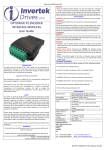
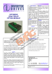
SAFETY NOTICES WARNING is given where there is a hazard that could lead to injury or death of personnel. CAUTION is given where there is a hazard that could lead to damage to equipment. It is the responsibility of the installer to ensure that the equipment or system into which the product is incorporated complies with the EMC legislation of the country of use. Within the European Union, equipment into which this product is incorporated must comply with 89/336/EEC, Electromagnetic Compatibility. OPTIDRIVE HVAC CASCADE EXPANSION MODULE User Guide WARNING Within the European Union, all machinery in which this product is used must comply with the Directive 89/392/EEC, Safety of Machinery. In particular, the equipment should comply with EN60204-1. CAUTION Store the Optidrive Option Module in its box until required. It should be stored o o in a clean and dry environment. Temperature range –40 C to +60 C. Install the Option Module into the Optidrive by inserting the module into the option module port of the Optidrive as shown in the mechanical installation section. Do not use undue force in inserting the option module into the port. WARNING Optidrives and the Option Modules should be installed only by qualified electrical persons and in accordance with local and national regulations and codes of practice. Electric shock hazard! Disconnect and ISOLATE the Optidrive before attempting any work on it. High voltages are present at the terminals and within the drive for up to 10 minutes after disconnection of the electrical supply. Where the electrical supply to the drive is through a plug and socket connector, do not disconnect until 10 minutes have elapsed after turning off the supply. DECLARATION All rights reserved. No part of this User Guide may be reproduced or transmitted in any form or by any means, electrical or mechanical including photocopying, recording or by any information storage or retrieval system without permission in writing from the publisher. Copyright Invertek Drives Ltd ©2010 The manufacturer accepts no liability for any consequences resulting from inappropriate, negligent or incorrect installation. The contents of this User Guide are believed to be correct at the time of printing. In the interests of a commitment to a policy of continuous improvement, the manufacturer reserves the right to change the specification of the product or its performance or the contents of the User Guide without notice. SAFETY This option is specifically designed to be used with the Optidrive HVAC variable speed drive product and is intended for professional incorporation into complete equipment or systems. If installed incorrectly it may present a safety hazard. The Optidrive HVAC uses high voltages and currents, carries a high level of stored electrical energy, and is used to control mechanical plant that may cause injury. Close attention is required to system design and electrical installation to avoid hazards in either normal operation or in the event of equipment malfunction. System design, installation, commissioning and maintenance must be carried out only by personnel who have the necessary training and experience. They must read carefully this safety information and the instructions in this Guide and follow all information regarding transport, storage, installation and use of the Option module, including the specified environmental limitations. Please read the SAFETY NOTICE carefully, and all Warning and Caution boxes elsewhere. WARRANTY All Invertek Drives Ltd (IDL) products carry a 2-year warranty, valid from the date of manufacture. Complete Warranty Terms and Conditions are available upon request from your IDL Authorized Distributor. STANDARDS CONFORMITY An Optidrive fitted with this Option complies with the following standards: CE-marked for Low Voltage Directive. IEC 664-1 Insulation Coordination within Low Voltage Systems. UL 840 Insulation Coordination for electrical equipment. EN50081-2 EMC Generic Emissions Standard, Industrial Level. EN50082-2 EMC Generic Immunity Standard, Industrial Level. Enclosure ingress protection, EN60529 IP00, NEMA 250. Flammability rating according to UL 94. SPECIFICATIONS OPT-2-CASCD-IN Optidrive HVAC (ODV-2) Optidrive P2 (ODP-2) * limited functionality Max Relay switching voltage: 250V AC / 30V DC Max Relay switching current: 6A (250V AC) / 5A (30V DC) Environnemental : -10ºC … +50ºC Conformity: IP20, UL94V-0 Terminal Torque: 0.5Nm (4.5 Ib-in) Model Number: Compatibility: MECHANICAL INSTALLATION 1) Option Module inserted into Optidrive Option Module Port 2) DO NOT use undue force in inserting the option module into the options port. 3) Ensure the option Invertek Drives Ltd module is fitted securely Offa’s Dyke Business Park before powering on the Optidrive. Welshpool Powys Part No. 82-OPT-2-CASCD-IN Version 1.01 / January 2010 4)SY21 Remove 8JFterminal block header from UK module prior to option tightening connections. Replace when wiring is completed. Tighten to Torque setting provided in Specifications. Tel: +44 (0) 1938 556868 Fax: +44 (0) 1938 556 869 email: [email protected] Web: www.invertek.co.uk Option Module Slot Option Module OPTION MODULE CONTROL TERMINALS Pin 1 2 3 4 5 6 OPTIDRIVE HVAC CASCADE OPERATION The Optidrive HVAC DOL Cascade control uses a maximum of three relays from the cascade option module and the 2nd user relay from the standard drive terminals, giving the potential for 4 separate pumps under DOL control. The cascade option module is required if the system requires more than 1 DOL pump or when the 2nd user relay on the drive is required for another function. The basic configuration for the drive and DOL pumps is shown below. Function Relay 3 Common Relay 3 Contact Relay 4 Common Relay 4 Contact Relay 5 Common Relay 5 Contact OPTIDRIVE HVAC CASCADE EXPANSION MODULE Relay 3 Relay 4 1 2 3 Relay 5 4 5 6 LED STATUS INDICATION The cascade module has a Status LED – LED A (Green). LED A: Constant Green Indication - Modular is OK LED A: Flashing Green Indication – No Communication with drive LED A: LED Off Indication – No power to module LED B is not used. LED A (Green) OPTIDRIVE HVAC DEFAULT OPERATION The additional relays will assume default configuration whilst the DOL cascade function is disabled. Default (none cascade) functions are listed in the table below) Once the DOL cascade function is enabled (P8-14 = 1) the relays will assume DOL operation as detailed in the ‘Optidrive HVAC cascade operation’ section of this manual. In this configuration the 2nd drive relay is used to control the first DOL pump with the cascade module controlling the remaining DOL pumps. In this configuration P2-18 must be set to 8 to configure the 2nd drive relay for DOL pump control. P8-14 must be set to enable the DOL cascade function and P8-15 must be set with the number of pumps that make up the cascade system (from 1 to 4). The relays in the cascade module are assigned automatically starting with the lowest numbered relay. If the 2nd relay is not assigned to DOL control then the configuration is as shown below and a maximum of 3 DOL pumps are permitted. Default Operation (DOL Cascade disabled, P8-14=0) Relay 3 Drive Healthy Indication (close on Healthy) Relay 4 Drive Fault Indication (close on fault) Relay 5 Drive Running Indication (close on enable) OPTIDRIVE HVAC PLC LOGIC OPERATION Relays on the HVAC Cascade Expansion module can be assigned functionality within the internal PLC logic (programmed via the OptiTools Studio software). In order to allow PLC configuration parameter P9-41 must be set to ‘1’ (user defined -PLC). When P9-41 is set to ‘1’ all default operation and cascade operation is automatically disabled and all extended relay function must be programmed through the PLC function.. See the OptiTools Studio software for further information. HVAC CASCADE RELAY CONFIGURATION SUMMARY P8-14 0 1 N/A P9-41 0 0 1 Function Selected Default Operation Cascade Operation PLC logic defined operation CONNECTION OF THE CASCADE MODULE TO AN OPTIDRIVE P2 The HVAC Cascade Expansion module can be used with a Optidrive P2 model drive (ODP-2). For Optidrive P2 operation the default or PLC defined functionality is available but there is no option to implement Cascade control. The table below shows relay configuration summary when the module is connected to an Optidrive P2. P9-41 0 1 Function Selected Default Operation PLC logic defined operation Default operation is identical to the Optidrive HVAC default operation. For this configuration only parameters P8-14 and P8-15 need be set and the relays in the cascade module are assigned automatically starting with the lowest numbered relay. When cascade mode is enabled (P8-14 = 1) the relays contained on the cascade option module are dedicated to the cascade function and can only be used for other functions if P9-41 is set to 1 and relay functions are defined through the PLC logic using the OptiTools Studio software.