1
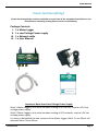
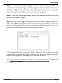
Installation and User Guide Version 0.5a Information in this document is subject to change without notice. © Copyright 2015 - Crucible Technologies. All rights reserved. Crucible Technologies is a trading name of Tele-Products Ltd. While the information contained in this document was correct at the time of printing, it may not be the latest version available. Please visit our website at http://www.crucible-technologies.co.uk to check for updates. Reproduction of any printed material, software or hardware without prior consent of Crucible Technologies is strictly forbidden. Meter Logger Manual Version 0.5a September 2015 USER MANUAL Thank you for purchasing the Meter Logger 100. This manual contains setup and general use instructions. Should you require any further information feel free to contact our support team on 01904 792211. Version 0.5a Page 3 USER MANUAL CONTENTS Have I got everything? 5 Installation 6 Meter Logger Installation - Connecting the Logger - Setting the Time/Date - Network configuration - Resetting the settings Using the Logger Webpages Configuring Your Meter Logger - Basic Meter Settings - Passwords - E-mail Settings - Data File Format - Saving Your Changes Developers Guide 11 11 13 14 15 16 18 Finding the Meter Logger IP - LoggerFind Details - JAVA LoggerFind Example - VB.NET LoggerFind Example 18 19 21 Downloading Data - How to Download Data - CSV Download Data - XML Download Data - Other Developers Data 22 22 23 24 After Sales Service & Guarantee Version 0.5a 6 8 9 9 25 Page 4 USER MANUAL Have I Got Everything? Please check the package contents and make sure you have all the equipment listed below. If you find you have something missing please contact us immediately. Package Contents I. 1 x Meter Logger II. 1 x Low Voltage Power supply III. 1 x Network cable IV. 1 x User Manual I II III IV Important Note about Low Voltage Power Supply Mark 1 Meter Loggers, with serial numbers ending in 001 to 030, require a 12V low voltage power supply. Mark 2 Meter Loggers, with serial numbers ending in 031 onwards, require a 5V low voltage power supply. It is easy to distinguish the two versions of the Meter Logger; Mark 1’s are 20mm tall whereas Mark 2’s are 40mm. Version 0.5a Page 5 USER MANUAL Installation Connecting the Meter Logger Step 1 – Unpack the Meter Logger parts and check the package contents with those on page 5. Step 2 – Connect the volt free pulse output of up to three utility meters to the input(s) of the Meter Logger. The example below is for a Northern Design Cube350V. Note : Only use VOLT FREE pulse connections. Any other connections may cause damage to the Meter Logger and will void the product warranty. Crucible Technologies recommends using twisted pair wiring. Version 0.5a Page 6 USER MANUAL Step 3 – Connect the Meter Logger to your network via the Ethernet connection. The Meter Logger will be assigned an IP via DHCP. If you need the Meter Logger to have a static IP you will need to connect it to a network that will assign it an IP before a static one can be assigned. Step 4 – Plug the low voltage power supply into a mains outlet and into the socket on the Meter Logger. Step 5 – Execute the LoggerFind software to find the Meter Logger IP address. Note: The LoggerFind software will not work over the internet or if there are routers in the network that do not propagate multicast signals. If you are unsure about this contact your systems administrator. If the LoggerFind utility locates any Meter Logger(s), the IP address(es) and name(s) will be displayed. Double clicking on a particular logger entry will load the web pages for that logger into your web browser. Visit http://www.crucible-technologies.co.uk/products/ML3P to download the LoggerFind software. Version 0.5a Page 7 USER MANUAL Setting the time and date The Meter Logger has a built in real time clock-calendar powered from a battery that keeps the time even when the unit is not connected to the external power supply. The Settings-Time pane on the web interface allows the method for setting the time to be selected. 1. User defined If the “Get time via SNTP” checkbox is not ticked then the time and date can be set manually. Ensure that the “Save Settings” button is clicked once the correct time & date have been entered. This will cause the Meter Logger to reboot and begin logging using the new values. 2. Using the SNTP facility If “Get time via SNTP?” checkbox is ticked the time and date will be automatically set using the Internet’s Simple Network Time Protocol (SNTP). After ticking the checkbox, ensure that the “Save Settings” button is clicked so that the Meter Logger reboots. On reboot, the unit will send an SNTP request to uk.pool.ntp.org and if a response is received within 10 seconds it will be used to update the time/date, otherwise the current system time will remain. Version 0.5a Page 8 USER MANUAL Network configuration The Settings-Network pane of the web interface allows the network connection parameters to be set. If you need to have a static IP address then this can be set by unticking the “Enable DHCP” tick box. The options to set the IP address, gateway, subnet mask and DNS servers will then become enabled. Resetting the settings If you need to reset the meter logger to factory defaults, this can be done by using the button on the side nearest the Ethernet connector. Unplug the unit from the power supply for at least 5 seconds then while holding down the button plug the unit in. If you hold the button for 4 seconds it will reset the time and network settings. CAUTION: If you keep holding for a further 5 seconds then all data will be erased from memory. Version 0.5a Page 9 USER MANUAL Reset procedure: 1. 2. 3. 4. 5. 6. 7. Version 0.5a Hold down the button on the side of the unit adjacent to the Ethernet connector. The button is internal to the Meter Logger and can be activated using a jeweller’s screwdriver or opened-out paper clip. Toggle power on the unit by unplugging, waiting 5 seconds then plugging in. All of the LEDs will illuminate. After 4 seconds, LEDs all go off and network/time settings reset. After 1 more second (5 total) the LEDs light up again. After 5 more seconds (10 total) the LEDs will all go off and the pulse data will be erased. Release the button adjacent to the Ethernet controller and the unit will reboot and enter normal operation. Page 10 USER MANUAL Using the Logger Webpages Home Page Enter the IP address of the Meter Logger into your browser’s location bar and the home page will be displayed: Version 0.5a Page 11 USER MANUAL Configuring Your Meter Logger Click on the “Settings” button to configure your Meter Logger for your particular installation. Basic Meter Settings Basic configuration of the Meter Logger is set via the Settings – Meter and Input pane, as shown below: The “Meter SiteID” parameter allows the location of the Meter Logger to be identified. This parameter can optionally be included in the data file sent by e-mail (see Settings-Email section) Version 0.5a Page 12 USER MANUAL The Meter Logger has three inputs. The inputs are numbered as per the following diagram: Input 1 Input 2 Input 3 The “Input x Name” parameter allows a user to define a unique identifier for the pulse data source. For example this could be the serial number of the utility meter. In the example shown on the previous page “Input 1 Name” has been set to D00L91018. The Input x Name parameter can be optionally included in the data file sent by e-mail. The “Input x Scaling Factor” allows the relationship between pulses and standard units to be defined. For example, many electricity meters generate a pulse every WattHour (WH) whereas the standard unit for electricity usage is the KiloWattHour (KWH). In this case the Scaling Factor should be set to 0.001 so that 1000 pulses are recorded as 1 KWH. The “Input x Units” allows the standard unit for the particular input to be specified. The “Input x Units” data is included in the data file sent via e-mail. Passwords To enable the user to restrict access to the meter data and/or the configuration of the Meter Logger, two levels of password protection can be set; one for administration of the settings and one for only viewing the data. The usernames associated with these access rights are: Administration user name: admin View data but not change settings user name: view Version 0.5a Page 13 USER MANUAL By default both users do not have a password set. We recommend that as a minimum an administration password is set as it is possible to reset all of the data from this page. Important Note: Passwords must be alphanumeric with a maximum length of 8. The settings web page will not allow you to enter anything that is not alphanumeric or longer than 8 characters. E-Mail Settings The e-mail feature of the Meter Logger is set via the Settings – Email pane, as shown below: If an entry is made in the “To:” parameter field the Meter Logger will attempt to send an e-mail to this address. The Meter Logger does not validate the address and will not report any error if the e-mail can not be sent. The e-mail will be sent from [email protected] and the subject will be “Logger - <<Meter SiteID>>” where <<Meter SiteID>> is the Version 0.5a Page 14 USER MANUAL setting of the “Meter SiteID” parameter in the Settings – Meter and Input pane. If an address is set in the “CC:” field, the e-mail will be cc’d to the specified address. Again the e-mail address is not validated and any failures are not reported. The “Frequency:” parameter defines how often e-mails are sent; the options are Daily, Weekly or Monthly. If set to Weekly, the e-mail is sent on Monday and includes data for the previous 7 days (Monday – Sunday). If set to Monthly, the e-mail is sent on the 1st of the month and includes data for the previous month. The “Daily Buffer:” parameter defines a mechanism for recovery in the event of e-mail send failure. If the initial e-mail send fails, the firmware will retry 10 times at hourly intervals. If the Frequency parameter is set to Daily and all 10 hourly retries fail, then the previous day’s data is included in the next day’s data send, up to a maximum number of days as defined by the Daily Buffer parameter. Once the Meter Logger has successfully communicated with the mail server then the data sent is reset to just the previous day’s data. The “Time:” parameter defines when the e-mails are sent. The Meter Logger operates on UTC time so be aware of any time zone corrections that need to be applied. The logged data is sent as an attachment to the e-mail in CSV format for easy import into third party software. Data File Format After importing into Excel, an example data file is shown below: Note for clarity the columns H to AU have been omitted. Version 0.5a Page 15 USER MANUAL Column A shows the SiteID. This column is included if the “Show Meter SiteID” tick box is checked. Column B shows the Meter Reference. If the “Input Identifier” parameter is set to “Number”, this will be 1, 2 or 3 depending on the input. If “Input Identifier” is set to “Name”, this will be the value from the “Input x Name” parameter. Column C is the date when the data was logged. Column D is the Units for the specified input obtained from the setting of the “Input x Units” parameter. Row 2 Columns E through AZ show the calculated energy usage for the halfhour period ending with the time specified in Row 1 e.g. the data in cell E2 is the energy consumed from 00:00:01 (hh:mm:ss) until 00:30:00. The energy consumption data is obtained by multiplying pulses logged during the period by the relevant “Input x Scaling Factor” parameter. So if the Meter Logger records 500 pulses in the half hour period and the Input Scaling Factor is set to 0.001, the data in the cell will be 0.5. The “Inputs to include in CSV:” parameter allows selection of which inputs are in the data file. Complete control is provided as the available options are: “1, 2 and 3”, “1 only”, “2 only”, “3 only”, “1 and 2”, “2 and 3” and “1 and 3”. In the case where not all 3 inputs are used, this ensures that the data file only contains relevant information. The “Include A separator” tick box provides for compatibility of the data file with third party energy management software by inserting an additional delimiter into the data file as per the following example: Saving Your Changes: Version 0.5a Page 16 USER MANUAL Once any parameter has been changed, ensure that the “Save Settings” button is clicked. This will cause the Meter Logger to reboot and activate the new settings. Version 0.5a Page 17 USER MANUAL Developers Guide Finding the Meter Logger IP The meter logger contains a LoggerFind feature that will allow developers to find the IP address of any units. This is done using multicast UDP packets that the unit responds to. The way this works is as follows: 1. A multicast packet is sent to port 30303 (default) with the data packet containing the character 'D' (default). 2. When this packet is read by the logger, it will respond with a string containing IP address, name and MAC address. The format of the data is IP;NAME;MAC for example "192.168.35.82;METER_LOGGER ;00-04-A3-1E-AE-82" this could then be broken down into separate parts using a simple explode command. It is worth noting that some routers do not populate multicast commands and hence may not find all of the units on the network. Version 0.5a Page 18 USER MANUAL JAVA LoggerFind Example Turn Over Version 0.5a Page 19 USER MANUAL Version 0.5a Page 20 USER MANUAL VB.NET LoggerFind Example Version 0.5a Page 21 USER MANUAL How to Download Data The Meter Logger provides an HTTP request interface to download data from the unit. Data can be downloaded in two different versions: CSV or XML. CSV Data Download A comma-separated values (CSV) file stores tabular data (numbers and text) in a plain-text format. In this instance this is a sequence of records separated by line breaks, each record containing a sequence of fields separated by commas (,). To make it easy for software developers to download data to their applications it is possible to download a CSV file containing the following data. Date (Year, Month, Day) Input Total pulses on that day Pulses for each half hour period To download this data you simply need to use a URL as follows: Pulse 1 - http://{Logger Pulse 2 - http://{Logger Pulse 3 - http://{Logger IP}/csv_input1.csv?month={month}&year={year} IP}/csv_input2.csv?month={month}&year={year} IP}/csv_input3.csv?month={month}&year={year} So if we wanted data from November 2011 we would do: Pulse 1 - http://192.168.35.82/csv_input1.csv?month=11&year=2011 Pulse 2 - http://192.168.35.82/csv_input2.csv?month=11&year=2011 Pulse 3 - http://192.168.35.82/csv_input3.csv?month=11&year=2011 An example of the data can be downloaded from the webpages of the meter. Version 0.5a Page 22 USER MANUAL XML Data Format An extensible markup language (XML) file is designed to structure, store and transport information. The schema is available within the Logger web pages. To make it easy for software developers to download data to their applications it is possible to download a XML file containing the following data. Date (Year, Month, Day) Input Total pulses on that day Pulses for each half hour period To download this data you simply need to use a URL as follows: Pulse 1 - http://{Logger Pulse 2 - http://{Logger Pulse 3 - http://{Logger IP}/xml_input1.xml?month={month}&year={year} IP}/xml_input2.xml?month={month}&year={year} IP}/xml_input3.xml?month={month}&year={year} So if we wanted data from November 2011 we would do: Pulse 1 - http://192.168.35.82/xml_input1.xml?month=11&year=2011 Pulse 2 - http://192.168.35.82/xml_input2.xml?month=11&year=2011 Pulse 3 - http://192.168.35.82/xml_input3.xml?month=11&year=2011 An example of the data can be downloaded from the webpages of the meter. Version 0.5a Page 23 USER MANUAL Other Developer Data The Meter Logger also has some web pages to allow you to get variables from the Logger. These are outlined below and should be accessed as follows: http://{Logger IP}/get/filename.html Where filename.html is one of the following: logger_name.html Will display the name/hostname of Meter Logger. input1_name.html Will display the name of input 1. input2_name.html Will display the name of input 2. input3_name.html Will display the name of input 3. input1_scale.html Will display the scaling factor for input 1 as used on the web graphs. input2_scale.html Will display the scaling factor for input 2 as used on the web graphs. input3_scale.html Will display the scaling factor for input 3 as used on the web graphs. NOTE: All website filenames are case sensitive and are all lowercase! Version 0.5a Page 24 USER MANUAL AFTER SALES SERVICE At Crucible Technologies we pride ourselves in providing excellent technical support. Having been established for more than 20 years, we know this makes us stand out from other suppliers. “We will provide unlimited telephone support for 30 days following purchase of the product. Following this period, we will provide unlimited e-mail support for the life of the product. This will allow us to keep the cost of the product competitive.” When contacting us for support, please have the following information to hand (or include in e-mail): Serial number of unit (usually on base of product) Where purchased from? (i.e. directly from us or a reseller) Your contact details including telephone and e-mail address Description of the problem GUARANTEE Your Crucible Technologies product is guaranteed for 1 year from the date of purchase. Please keep your invoice as proof of purchase. Should a problem arise with the product, please contact: [email protected] for technical assistance. If you wish to return your product, please contact us via the details on the back page and instructions for returning the product will be given. If you send any items back to us without arranging a returns number then we do not guarantee any repair or refund of the item. This guarantee does not affect your statutory rights. Version 0.5a Page 25 Crucible Technologies 11 Glaisdale Road Northminster Business Park York YO26 6QT United Kingdom www.crucible-technologies.co.uk [email protected]