1
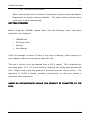
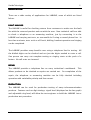
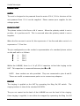
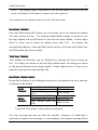
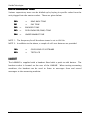
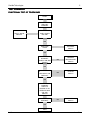
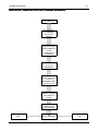
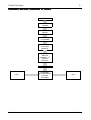
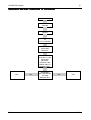
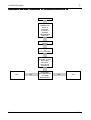
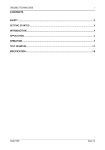
Crucible Technologies
1
CONTENTS
SAFETY ................................................................
................................................................................................
............................................................................
............................................2
............ 2
GETTING STARTED ................................................................
...........................................................................................
...........................................................3
........................... 3
INTRODUCTION................................
INTRODUCTION ................................................................
................................................................................................
................................................................4
................................ 4
APPLICATION ................................................................
................................................................................................
...................................................................
...................................5
... 5
OPERATION ................................................................
................................................................................................
......................................................................
......................................6
...... 6
TEST EXAMPLES ................................................................
..............................................................................................
..............................................................11
.............................. 11
SPECIFICATION ................................................................
...............................................................................................
...............................................................16
............................... 16
Labline
Issue 3.1
Crucible Technologies
2
SAFETY
Read this manual completely before using the instrument.
1.
The LABLINE is designed to behave like an exchange line therefore only
telecommunication apparatus designed to connect to telephone lines must
be connected to it.
2.
Under no circumstances must the LABLINE be connected to the Public
Switched Telephone Network (PSTN) or any PABX extension ports.
3.
When
using
the
LABLINE
to
test
the
performance
of
unapproved
telecommunication apparatus, due consideration must be paid to any hazard
involved.
4.
WARNING The connection sockets have high voltages present during
Ringing and Pulse dialling. Although this is not hazardous, it can be painful.
5.
The unit is designed to be powered from a 230 V, 50 Hz source. The IEC
Power Lead provided is fitted with a 5 Amp fused mains plug.
6.
The Mains Switch at the IEC Socket needs to be in the Off position to isolate
the unit from the mains.
7.
There are no user serviceable parts in this unit.
Under no circumstances
should the user attempt to open the unit. If opened, the warranty will be
invalidated.
8.
Should the unit require a service, repair or calibration, please return it to a
recognised dealer or to:
Cricuble Technologies
11 Glaisdale Road
Northminster Business Park
Upper Poppleton
York YO26 6QT
Labline
Issue 3.1
Crucible Technologies
3
Tel: +44 (0) 8702 60 60 82
When returning the unit to Crucible-Technologies, please contact the Repairs
Department to receive a Returns Number. The owner will be advised of any
costs prior to work commencing.
GETTING STARTED
Before using the LABLINE, please check that the following items have been
included in the shipment.
•
LABLINE Unit
•
IEC Power Lead
•
Handset
•
User Manual
Check for damage in transit. If there is any sign of damage, please report it to
your supplier and do not attempt to repair the unit.
The unit is factory set to be powered from a 230 V supply. This is indicated on
the rating plate. (If a 110 V unit has been supplied, the rating plate will indicate
this). Please ensure that this product is powered from the correct source. The
apparatus is CLASS II double insulated construction, so does not require a
protective earth connection.
UNDER NO CIRCUMSTANCES
CIRCUMSTANCES SHOULD THIS PRODUCT BE CONNECTED TO THE
PSTN.
Labline
Issue 3.1
Crucible Technologies
4
INTRODUCTION
The LABLINE is a bench top telephone line simulator designed to test a wide range
of telecom products.
It simulates a telephone line, enabling one to test most
functions of a telephone on one instrument.
The LABLINE provides a realistic simulation of telephone lines. The feed voltage
applied to the Unit Under Test (UUT) is 48 V and the ring voltage is a real 70 V, 25
Hz signal with DC backing. This ensures that telecommunication apparatus that
work on the LABLINE are sure to work on real telephone lines.
It is useful for engineers who need to test products. However, the controls are
straightforward to use which makes it ideal for non-technical personnel.
Labline
Issue 3.1
Crucible Technologies
5
APPLICATION
There are a wide variety of applications for LABLINE, some of which are listed
below:
FAULT ANALYSIS
The LABLINE is useful for checking returns from customers to make sure the fault
lies with the returned product and not with the user. Non-technical staff are able
to check a telephone or an answering machine, just by connecting it to the
LABLINE and carrying out tests, as one would do if using a normal phone line. In
less than a minute, tests such as off-hook, dialling, handset operation and ringing
can be completed.
The LABLINE provides many benefits over using a telephone line for testing. All
the dialled digits can be checked and not just the digits needed to route a call.
One person can carry out complete testing as ringing starts at the push of a
button. No call costs are incurred.
REPAIR
The LABLINE provides a telephone line on every technician’s workbench.
This
allows products to be checked as repairs are carried out. On completion of the
repair, the telephone or answering machine can be fully checked including
operation with switchable polarity and line current.
PRODUCTION
The LABLINE can be used for production testing of many telecommunication
products. Features such as digit timings, signal level (displayed on the bar graph)
and adjustable ring level, will allow the test engineer to build the LABLINE into a
production test procedure.
Labline
Issue 3.1
Crucible Technologies
6
OPERATION
SUPPLY
The unit is designed to be powered from the mains 230 V, 50 Hz. Versions of the
unit powered from 110 V can be supplied. Please contact your supplier for this
voltage option.
PHONE SOCKET
The phone socket is fed from a 48 V source. When the polarity switch is set to
positive, A is positive wrt B. This is reversed when the polarity switch is set to
negative.
When the line current is set to Hi, this represents a 1 km line and when set to Lo it
represents a 7.5 km line.
The pin configuration on the socket is representative of a standard phone socket
on the wall and is as follows:
A
B
E
S
⇒
⇒
⇒
⇒
Pin
Pin
Pin
Pin
2
5
3
4
Within the LABLINE, there is a 1.8 µF/250 V capacitor to feed the ringing to the
UUT. This capacitor is connected between pins B and S.
NOTE: 4mm sockets are also provided. They are connected to pins A and B.
These are useful as measurement points or to connect any adapters.
RINGING
The ringing is applied to the UUT by operating the Ring On/Off switch.
The
ringing cadence is that of the standard UK PSTN.
The pre-set control at the back of the LABLINE can set the level of the ringing.
Once ringing is applied, it can either be stopped by operating the Ring On/Off
Labline
Issue 3.1
Crucible Technologies
7
switch or by seizing the line (i.e. answering the call) with the UUT.
NOTE: If continuous ringing is required for test purposes, then turn power on
whilst holding the Ring Switch down. After about 5 seconds release the switch.
The LABLINE will generate ringing continuously
DIAL TONE
The Dial Tone provided on the LABLINE is a realistic 350 + 440 Hz as found on
most modern exchanges. This is presented to the UUT when it seizes the line
prior to dialling. However, if the line is seized in response to ringing no dial tone
is applied.
DIALLING
The digits dialled by the UUT are shown on the 8 digit LCD. The digits can be
Pulse, Tone or both.
The Tone digits are shown with a dot underneath to
differentiate them from the Pulse digits. The timing limit on the Make and Break
of Pulse dialling are set carefully to detect any problem that may exist. The level
of tones is displayed on the Bar Graph.
A Time Break Recall (TBR) signal is either displayed as a Pulse digit 1 or R
depending on its timing. If the break time is less than 80 mS then a Pulse digit 1
is displayed. If the break is greater than
80 mS then an R is displayed. This way
the time limits for Pulse break are not compromised. An Earth Recall is shown as
an E on the LCD display.
When more than 8 digits are dialled and there is a pause of more than 5 seconds
the display starts to scroll all the digits dialled. A maximum of 64 digits can be
detected and displayed.
When the UUT is On-line, the display scrolling can be frozen by pressing the Ring
On/Off button.
In the frozen mode the display flashes. The freeze can be
terminated by the operation of the Ring On/Off button or by dialling a digit.
Labline
Issue 3.1
Crucible Technologies
8
NOTE: The display freeze only works in the On-line mode, as in the Off-line
mode, the Ring On/Off button is used to turn the signal on.
The scrolling of the display carries on in the Off-line mode.
PULSE DIAL TIMINGS
Pulse dial Make/Break/IDP timings can be brought up on the display by dialling
200 after seizing the line. The displayed Make/Break timings are based on the
last digit dialled and the IDP based on the last two digits dialled. Further digits
(Pulse or Tone) can be timed by dialling these after 200.
The display will
automatically update to show the Make/Break timings of the last digit dialled and
the IDP between the last two digits.
TONE DIAL TIMINGS
Tone dialling On/Off times can be displayed by entering 200 after seizing the
line. On timings are based on the last digit dialled whilst Off timings are based
on the pause between last two digits dialled. Further digits (Pulse or Tone) can be
timed by entering these after dialling 200.
PULSE DIAL TIMING CHECK
CHECK
During Pulse dialling, if the following timing errors are detected, an error message
is flashed on the display:
MAKE
TIMINGS
BREAK
TIMINGS
Limits 33.3 mS ± 30%
Low timing gives an error
High timing gives an
error
Limits 66.6 mS ± 30%
Low timing gives an error
High timing gives an
error
MKE<23 mS
MKE>43 mS
MKE<46 mS
MKE>86 mS
Transients of less than 5 mS duration are ignored.
The error message will time out after five seconds. However, if a valid digit is
detected or another error message is to be displayed, the original message will be
Labline
Issue 3.1
Crucible Technologies
9
overwritten.
Labline
Issue 3.1
Crucible Technologies
10
DIAL UP SUPERVISORY TONES
Various supervisory tones can be dialled up by keying in specific codes from the
unit plugged into the master socket. These are given below:
300
⇒
RING BACK TONE
301
⇒
PAY TONE
302
⇒
ENGAGED TONE
303
⇒
PATH ENGAGED (PARK) TONE
304
⇒
UNOBTAINABLE TONE
NOTE 1: The frequency for all the above tones is set to 400 Hz.
NOTE 2: In addition to the above, a couple of self-test features are provided.
100
⇒
GIVES ISSUE OF SOFTWARE
999
⇒
TESTS LCD
HANDSET
The LABLINE is supplied with a handset fitted with a push-to-talk button. The
handset socket is located on the rear of the LABLINE. When testing answering
machines, the handset can be used to listen to messages from and record
messages to the answering machine.
Labline
Issue 3.1
Crucible Technologies
11
TEST EXAMPLES
FUNCTIONAL TEST OF TELEPHONES
TELEPHONES
START
PLUG UNIT IN
AND LIFT
HANDSET
FAULTY HOOK
SWITCH
NO
LINE LOOPED
LED ON?
YES
HEAR DIAL
TONE?
NO
HANDSET
RECEIVER
FAULTY
NO
HANDSET
MICROPHONE
FAULTY
NO
KEYPAD
FAULTY
NO
RINGER
FAULTY
YES
SPEAK INTO
HANDSET,
SPEECH ON BAR
GRAPH?
YES
DIAL 1, 2, 3…9,
0
SEE DIGITS ON
DISPLAY?
YES
REPLACE
HANDSET
CHECK IF
RINGER IS ON
OPERATE RING
ON/OFF
SWITCH
TELEPHONE
RINGING?
YES
PASS
Labline
Issue 3.1
Crucible Technologies
12
RING DETECT SENSITIVITY
SENSITIVITY ON AUTOAUTO-ANSWER APPARATUS
START
SET UNIT NOT
TO ANSWER.
PLUG INTO
LABLINE
HOLD RING
SWITCH DOWN
AND POWER ON
TO GET
CONTINUOUS
RINGING
CONNECT DVM
TO 4 mm
TERMINALS
ADJUST RING
LEVEL CONTROL
TO GET
REQUIRED LEVEL
(eg 20 V rms)
SWITCH LABLINE
OFF AND ON
AGAIN
OPERATE RING
SWITCH TO
START RINGING
PASS
Labline
YES
UNIT
AUTO-ANSWERS?
NO
FAIL
Issue 3.1
Crucible Technologies
13
ANSWERING MACHINE CLEARDOWN
CLEARDOWN TO SILENCE
START
PLUG UNIT IN TO
LABLINE
OPERATE RING
SWITCH
WAIT FOR UNIT
TO ANSWER
LISTEN TO
OUTGOING
MESSAGE
PRESS TO TALK
AND USE
HANDSET TO
LEAVE A
MESSAGE
RELEASE BUTTON
PASS
Labline
YES
ANSWERING
MACHINE DROPS
LINE IN 6
SECONDS?
NO
FAIL
Issue 3.1
Crucible Technologies
14
ANSWERING MACHINE CLEARDOWN
CLEARDOWN TO LINE BREAKS
BREAKS
START
PLUG UNIT INTO
LABLINE
OPERATE RING
SWITCH
WAIT FOR UNIT
TO
AUTO-ANSWER
LISTEN TO
OUTGOING
MESSAGE
DURING THE
PLAYING OF THE
OUTGOING
MESSAGE,
OPERATE LINE
BREAK SWITCH
MOMENTARILY
PASS
Labline
YES
ANSWERING
MACHINE DROPS
THE LINE
IMMEDIATELY?
NO
FAIL
Issue 3.1
Crucible Technologies
15
ANSWERING MACHINE CLEARDOWN
CLEARDOWN TO EXTENSION PHONE
PHONE PICK UP
START
PLUG UNIT INTO
LABLINE AND
USING A
DOUBLER,
PLUG IN A
NORMAL
TELEPHONE IN
PARALLEL
OPERATE RING
SWITCH
WAIT FOR UNIT
TO
AUTO-ANSWER
DURING THE
PLAYING OF THE
OUTGOING
MESSAGE,
PICK UP THE
TELEPHONE
PASS
Labline
YES
ANSWERING
MACHINE DROPS
THE LINE
IMMEDIATELY?
NO
FAIL
Issue 3.1
Crucible Technologies
16
SPECIFICATION
MASTER SOCKET
DC Voltage
Feed Bridge
DC Resistance
DIAL TONE
Frequency
Level
48 V ± 5%
2 x 200 Ω ± 10%
180 Ω ± 10% (= 1 km line)
1380 Ω ± 10% (= 7.5 km
line)
350 Hz + 440 Hz
-8 / -14 dBm
Cadence
70 V ± 10% rms (factory
default)
Adjustable from 0 V to 95 V
rms
25 Hz
AC (near sinusoid), DC
backed
PSTN
PULSE DIALLING
Make
Break
IDP
On-Hook
Off-Hook
TBR
25-41 mS
50-82 mS
>200 mS
>300 mS
>200 mS
80-110 mS
TONE DIALLING
Tone Time
Accept Frequency
Reject Frequency
>40 mS
± 1.5%
± 3.5%
RINGING
Voltage
User Level
Frequency
Type
BAR GRAPH
Range
Top LED set to –1 dBm ± 1
dB
3 ± 1 dB per LED
TOLERANCE
unless otherwise
specified
Frequency
Timing
Level
± 10%
± 10%
± 3 dB
POWER
Mains
230 V, 50 Hz, 50 mA
Labline
Reference
Issue 3.1