1
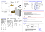
1.0 DESCRIPTION
The DM540X is an intrinsically safe battery powered indicator
designed to be used in conjunction with a Pt100 temperature
sensor. Temperature is indicated directly on the large LCD digital
display in degrees Celsius or Fahrenheit, monitoring and
updating maximum and minimum memories which may be
displayed at any time on demand.
DM540X
Intrinsically Safe
Digital
Thermometer
Designed, manufactured and supported by :
Green Lane, Tewkesbury
Glos. UK
GL20 8DE
Tel: 01684 296818
Fax: 01684 293746
Every effort has been taken to ensure the accuracy of this
specification, however we do not accept responsibility for
damage, injury, loss or expense resulting from errors and
omissions, and we reserve the right of amendment without
notice.
Stock code : 52-314-2082-01
Issue :01
The instrument is fitted with a M16 process entry which can
accept a wide range of integral or remotely mounted sensors.
(Subject to compliance with system certificate Ex94C2450).
The unit incorporates stable high accuracy components and a
microprocessor which continuously self calibrates, thus ensuring
a high precision instrument which never needs calibrating during
normal use.
2.0 RECEIVING AND UNPACKING
Please inspect the packaging and instrument thoroughly for any
signs of transit damage. If the instrument has been damaged,
please notify your supplier immediately.
3.0 SPECIFICATION @ 20°C
Ambient Temperature Range 0-40°C.
Measuring Range
-50.0 to 400.0 deg C
or -58 to 600 deg F
Resolution
0.1 deg C or 1 deg F
Accuracy
+/- 0.1 deg C +/- 0.15 % reading
+ sensor errors
or +/- 1 deg F + sensor errors
Stability
+/- 0.01 deg C / year.
Sensor
3 wire PT100 to BS1904
or DIN 43760
Sensor errors must be added to
indicator errors to obtain overall
measurement errors.
Sensors with a choice of
accuracies are available.
Lead effects
Insignificant for lead resistances
< 10R per leg assuming all legs
are equally matched.
Display
4 digit LCD with MAX, MIN, deg C,
deg F and low battery legends.
Batteries
4 x MN1500 (AA).
Approximate battery life
@ 25 deg C ambient.
36 weeks -1 second update rate.
1.5 years - 6 second update rate.
2.25 years -12 second update rate.
Mechanical.
100mm diameter stainless steel
housing with polycarbonate
front membrane.
Warm up time
1.5 minutes
Intrinsic Safety
Apparatus EEx ia IIc T4
ApprovalsCert. No. BAS Ex94C2449
System Cert. No. BAS Ex94C2450
EMC Compatibility Complies with directive 89/336/EEC + 92/31 EEC
4.0 INSTALLATION AND WIRING
4.1
INSTALLATION MUST BE CARRIED OUT IN
ACCORDANCE WITH BS5345 - CODE OF
PRACTICE FOR INSTALLATION OF ELECTRICAL
EQUIPMENT IN HAZARDOUS AREAS.
4.2
For safe operation the battery cover MUST REMAIN
IN PLACE whilst the apparatus is in a hazardous area.
4.3 General Recommendations
The instrument is a high accuracy digital thermometer. In order
to ensure correct operation the following precautions should be
observed:
The instrument should be stored in a dry clean environment
and remain in its original packaging prior to installation.
The indicator should not be installed adjacent to electro
magnetic starters, contactors, thyristor power units or
electric switch gear.
Any cleaning of the instrument should be carried out using
a mild detergent and a soft cloth. No solvents or abrasive
cleaners should be used.
Any external cable entries or cables glands used in the
installation should maintain the IP65 rating.
Any installation should ensure that the instrument does not
operate outside it's recommended operating limits. If in
doubt, use a remote sensor.
4.4 Range Selection
The indicator can display either degrees Celsius or degrees
Fahrenheit. Selection of the degrees Fahrenheit range is made
by the fitting of link 1, see diagram below. The link is factory set
in the ``parked'' position for degrees Celsius operation. The units
are indicated on the display.
Fig 1 Connections & Links
Fig 2 DM540 Case Styles
To clear either memory hold both buttons simultaneously for
three seconds. This causes both the MAX legend and the MAX
value to flash, pressing the MAX button again at this point will
reset the MAX memory. Alternatively pressing the MIN button will
leave the MAX memory and cause the MIN legend and the MIN
value to flash, pressing the MIN button again will reset the MIN
memory. In short pressing the same button as the flashing legend
resets that memory.
Note :
4.5 Battery Life
The standard battery life is typically 1.5 years at 25 deg. C
ambient. The battery life may be extended by increasing the time
between measurements from the standard 6 seconds to 12
seconds. This is achieved by fitting a link in position 5. When
operated in the 12 second update mode, the battery life is
extended to 2.25 years typically. Similarly the link may be fitted
in position 2 for 1 second measurement interval
5.0 CALIBRATION
Accurate measurement is achieved by comparing the resistance
of the sensor to an accurate, stable, integral standard resistor.
The unique design of the circuitry ( patent applied for ) means
that any errors introduced by the measurement circuit are
negligible, the net result being that there is no need to calibrate
the instrument during its entire life.
If a calibration error is suspected, first check the probe and if
correct, the instrument should be checked using a standard
calibrated resistance box. If an error is found, the instrument
should be returned to your supplier.
In 6 second update mode when there is approximately 1 month
of battery life remaining, the low battery symbol will be displayed
in the lower right corner of the LCD. After this period, the correct
operation of the instrument cannot be guaranteed. If the
instrument is configured in 12 second update mode, the low
battery indicator will show when there is approximately 2 months
of battery life remaining.
Please note that operating the instrument at ambient temperatures
exceeding 25 deg C may result in reduced battery life.
NOTE: Panel wall mount versions are retained through 3 hole
Ø4.5 min equip on 115mm PCD.
Fig 3 DM540 Front Panel
4.6 Replacing The Batteries.
Carefully open the case by twisting the ring bezel anticlockwise
and lift the front panel off. Unplug the sensor and remove the
COMPLETE DISPLAY ASSEMBLY from the hazardous area
(The battery cover must NOT be removed except in a SAFE
AREA). Unscrew the three screws retaining the battery cover
and remove the cover. Remove the four batteries from the
battery holders and replace with new ones making sure to align
the polarity markings on the batteries to those on the battery
holder. Refit the battery cover and secure all three screws
BEFORE returning the apparatus to the hazardous area. Plug in
the sensor and reassemble the case ensuring that the gaskets
are fitted and that the ring bezel is tight to ensure sufficient
sealing. Check correct operation.
Note : An incorrect reading may appear for the first 6/12 seconds.
4.7 Sensor Wiring.
The instrument will operate with optimum accuracy with a three
wire sensor. A two wire sensor can be used but this may result
in reduced accuracy. The sensor should be connected to the
instrument via the three terminal connector mounted on the
reverse of the printed circuit board as shown in figure 1.
If no memory is cleared within 6 seconds, the instrument
will time-out back to the current temperature display.
6.0 TROUBLESHOOTING.
A number of self checking and diagnostic routines are included in
the instrument which assist fault finding in the event of error
conditions occurring.
DISPLAY
No display
POSSIBLE CAUSE
ACTION
Batteries completely dead. Replace batteries.
System failure
Return to supplier.
Erratic display Poor connections.
Excessive electrical noise.
Water ingress.
Check wiring.
Re-site instrument.
Clean, dry & re-fit
glands.
Check seals.
``- - - -'' displayed Watchdog error -
Check wiring &
sensor.
sensor open circuit
or sensor short
circuit.
Return to supplier.
System failure.
4.8 MAX / MIN Operation
The digital thermometer stores the maximum and minimum
temperatures which have occurred since its memories were last
cleared. To view the required memory, press the respective button on the front panel. The required temperature and the appropriate legend will be displayed for a short time interval, depending upon the position of links 2 + 5 (see section 4.5) before
returning to the current value.
"Lo'' displayed Sensor temp. less than -50 deg C (-58 deg F)
``Hi'' displayed Sensor temp. greater than 399.9 deg C (600 deg F)
52-314-2082-01