1
Analox 1300 User Manual
1
IMPORTANT SAFETY WARNINGS.
THIS PAGE SHOULD BE READ AND UNDERSTOOD BY ALL PERSONNEL CONCERNED
WITH THE INSTALLATION, OPERATION AND MAINTENANCE OF THIS INSTRUMENT.
The Instruments in the 1300 Range are NOT suitable for operation in Hazardous Area, as defined by
the British Standard BS 5345 Part 4.
ELECTRICAL SHOCK HAZARD WARNING.
The electrical power used in the 1300 Range of Instruments, may be at a voltage sufficient to endanger
life. Before carrying out any maintenance or repair, persons concerned must ensure that the equipment is
disconnected from any Mains supply and tests made to ensure that isolation is complete. When the
supply cannot be disconnected, functional testing, maintenance or repair should only be undertaken by
qualified persons, who are aware of the precautions necessary when carrying out such operation.
DISPLAY RESOLUTION & ACCURACY.
The Digital displays used in this series of instruments are of the 3 1/2 digit type. The indicating accuracy
of such a Display is limited to the resolution ie Plus or Minus the reading on the Least Significant Digit
(the right most Digit). If the Quoted indicating range is 0.00 to 100.00 then when the display reads 0.00
the actual input signal could be between -0.004 and +0.004. The Least Significant Digit will change
from 0 to 1 when the absolute value changes from 0.004 to 0.005
POTENTIAL HAZARD WHEN DETECTING FLAMMABLE GAS.
When a concentration of Flammable gas greater than 100% LEL is detected, using Pellistor type
Sensors, if the concentration continues to increase well beyond 100% LEL, the Sensors will eventually
produce a DECREASING output due to lack of Oxygen, required to maintain local combustion at the
Sensor surface. The Instrument incorporates an OVER-RANGE Visual indication together with two
Alarms. If the High Alarm is latched on, but the indicated reading is BELOW the High setpoint, then the
user should be aware that a HIGH concentration of gas COULD still be present.
IF THIS SITUATION ARISES, THEN THE AREA BEING MONITORED, SHOULD BE
EVACUATED AND FULLY VENTILATED UNTIL THE INSTRUMENT INDICATES A SAFE
CONDITION.
2
ANALOX 1300 Series used with SIMRAD Sensor
When the ANALOX 1300 Series of Instruments are used with the SIMRAD type sensor units, and the
Optical system of the Sensor becomes dirty or partially obscured, the Sensor will produce an output, in
normal air, of less than 4 milliamps. This condition was indicated by a 'CLEAN OPTICS' warning LED
on the previous range of Instruments. On the current 1300 Series instruments, this warning is indicated
by the 'FAULT' LED which will illuminate when the input current from the sensor falls about 10% of Full
range indicated value, BELOW 4 milliamps. eg. If a channel has a full range of 100ppm, then the
'FAULT' LED will operate if the Indicated value falls below about -10ppm.
Note : On no account should the DC Power for the SIMRAD sensor be drawn from the 24 volt DC
output of the ANALOX 1300.
3
IMPORTANT NOTES
Any adjustments or repairs to the ANALOX 1300 range of instruments should only be carried out by a
competent electronic engineer, familiar with Instrument technology.
S.A.E.P. Ltd. WILL NOT ACCEPT RESPONSIBILITY FOR ANY EVENTS OCCURRING AS
A RESULT OF UNAUTHORISED ADJUSTMENTS OR REPAIRS TO THE INSTRUMENTS.
S.A.E.P. Ltd. operate a policy of continuous improvement to their products and reserve the right to
change the design, components and specification of their equipment, without prior notice. However, the
company will endeavour to keep their customers informed of any changes, which they consider to be
relevant to the continued satisfactory performance of their products. The information in this document is
given in good faith and is believed to be correct, at the time of publication.
The purchasers attention is drawn to the Appendix B at the end of this manual, with regard to Warranty
Conditions.
Further technical assistance may be obtained by contacting S.A.E.P. by one of the means indicated
below.
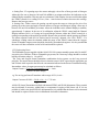
Scottish Anglo Environmental Protection Ltd.
Units 4 and 5, Wainstones Court,
Stokesley Industrial Park
STOKESLEY. Cleveland TS9 5JY
Telephone : 0642 711400 Fax : 0642 713900
This Manual is Issue 3 : Dated : 10th February 1995
4
SECTION 1. OPERATING INSTRUCTIONS.
1.1 INTRODUCTION
The ANALOX 1300 Surveyor Instrument is designed to operate in conjunction with external sensors,
provide indication of the concentration of oxygen, flammable or toxic gases and initiate alarms if the
measured concentration falls outside pre-set limits. The Instrument is built in a glass reinforced,
polycarbonate wall mounting cabinet and provides a means of monitoring up to 4 channels of any
physical parameter which can be converted to an electrical signal, eg Oxygen, Toxic or Combustible gas
concentrations, Temperature, Pressure, RH% etc.
The Instrument provides the following facilities :
a. Individual Digital Display for each channel, calibrated in engineering units.
b. Audible and Visual alarm indication.
c. Relays on all alarm circuits if required.
d. 4-20mA Output on each channel.
e. Easy calibration and alarm setpoint adjustment.
f. Fault and Over range Indications.
g. Optional Isolated 4-20mA Output
The Instruments are designed to operate from a mains supply of 110v ac, 220v ac, 240v ac or 24 volt
DC. There is also provision for an optional Battery Back-up power unit which will provide uninterrupted
operation, for a period, in the event of mains failure.
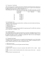
The Instruments are identified for ordering purposes as follows :
1300 / 1 Single Channel
1300 / 2 Dual Channel
1300 / 3 Three Channel
1300 / 4 Four Channel
1.1.1 Weight and Dimensions (Overall)
Height Width Depth Weight
256mm
314mm
118mm
2.5Kg
See also Figure 9 at the end of the manual which shows an outline diagram of the ANALOX 1300
enclosure.
5
1.2 GENERAL DESCRIPTION
The ANALOX 1300 Surveyor is a multi channel monitoring system designed primarily for the detection
and display of concentration of Oxygen, Toxic and Flammable gases, together with two user adjustable
alarm circuits. The Instrument was designed using the 'Motherboard/Daughterboard' principle and each
channel functions totally independently of the others, the only common point being the main power
supply. As such, it is a simple matter to upgrade a single channel Instrument to a two or more channel
Instrument, without even removing the device from its normal mounting position. All that is required is
additional Daughter boards and a replacement front panel. This method of construction also provides for
simple, rapid servicing, in the event of channel card faults.
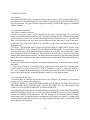
Each Channel can be configured to operate from a variety of input signals :
a. 4-20mA Loop Powered sensor/transmitters.
b. Pellistor Half-bridge Flammable sensors.
c. Voltage level signals.
d. Millivolt level signals.
e. 4-20mA Live output sensors (Simrad etc.)
Each channel Daughterboard provides excitation power for either Loop powered 4-20mA transmitters,
OR Flammable sensors. Adjustment is provided in the power supply for the Flammable sensors and
both supplies are protected against short circuit faults in the sensors or associated wiring. Measured
level indication is provided for each channel, by Liquid Crystal Displays (LCD), in the form known as '3
1/2 digits'. This means that the maximum reading displayed, disregarding the decimal point, is '1999'.
Calibration is easily carried out using the Zero and Span adjustments for each channel, on the front panel
of the Instrument.
User adjustable HI and LO alarms are incorporated in each channel, together with Fault and
over-range indication. The HI, LO and fault alarms can be fitted with 3 optional relays, which can be
configured, by jumper links, to operate in a normally energised or de-energised state. In the latter case,
this provides a 'Fail-Safe' condition. The alarm Setpoints can be displayed on the individual Channel
LCDs by operating a spring loaded switch on the front panel.
The HI and LO alarms can be individually configured, using jumper links, to operate on a High going or
Low going signal and may be of the latching or non-latching type. The Fault alarm circuit operates when
the measured input signal drops below the Zero point by about 6% of full range and is useful for
indicating open circuit sensor connections or obscuration of the Optical system in an Infra red type
sensor.
The Over-range alarm operates when the input signal exceeds the full range by about 6%. An 'Inhibit'
function is built in to each channel to prevent alarm triggering during calibration or alarm setpoint
adjustment. This function also operates during the first 30 seconds after initial application of power, to
allow the sensors to settle. Each channel also provides a 4-20mA analogue output, which is proportional
to 0-100% of full scale reading for the particular channel. A common Audible alarm, which activates
with the onset of any alarm, is built in to the Instrument together with an 'Alarm Accept' push button
switch, which mutes the audible alarm.
The systems may be specified at ordering stage, to include or exclude any combination of relays, in the
Alarm circuits.
6
1.3 CONTROLS AND INDICATORS
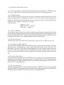
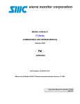
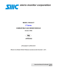
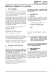
1.3.1 Controls and indicators on the front panel of the Instrument are shown in Fig 1. The following text
refers to any single channel of a multi channel Instrument. They have the following functions :
1.3.2 The Digital Display
This is used to provide an indication of the measured concentration of the gas detected by the sensor
connected to that channel. In conjunction with the 'LO / HI' switch, in the Left half of the panel, the
Display can also indicate the Alarm setpoints. It may be scaled in any units - the measured parameter
being shown in the 'Window' on the far left of the panel.
Typical scales are
: Oxygen 0 - 25.0%
: Flammable Gas 0 - 100% LEL
: Toxic Gas 0 - 100ppm etc.
1.3.3 The HI / LO Switch
This switch is a three position device which is normally spring biassed to its central position. In this
position, the Digital Display indicates the measured gas concentration. If the switch is pushed to the Left,
then the HI alarm Setpoint will be displayed and if pushed to the Right then the LO alarm Setpoint will
be displayed. This allows easy reading and adjustment of the alarm Setpoints.
1.3.4 The Power Indicator
Indicates the presence of the main power supply from ac mains, 24v dc or Back-up power unit.
1.3.5 The Alarm Trip LEDs (HI & LO)
These Red LEDs will initially flash On and Off if the alarms are configured in the Latching mode and the
appropriate alarm circuit trips. If the 'Alarm Accept' push button switch on the Lower side of the
Instrument is operated, the LED will then remain illuminated in a steady condition, until the alarm state
clears. If the alarms are configured in the Non-latching mode then if an alarm condition occurs, the
appropriate LED will illuminate in a steady condition for as long as the alarm state exists, and then turn
Off.
1.3.6 The Fault LED (FAULT)
If the input signal level falls below the normal Zero level, eg 4mA on a Loop powered sensor by
approximately 6% of full range, then the Fault alarm circuit will trip and the 'FAULT' LED will illuminate.
It will remain in that condition until the input signal is greater than the alarm trip point, at which time it will
turn off. This is a non-latching alarm.
1.3.7 The Over-range LED
If the input signal level rises to a value of approximately106% of full scale, then the Over-range alarm
will trip and 'O/RNG' LED will illuminate. It will remain in that condition until the input signal falls below
the alarm trip point, at which time it will turn off. This is a non-latching alarm.
7
1300/1 has Second from top channel only.(Channel 2)
1300/2 has Middle Two channels only.(Channels 2 & 3)
1300/3 has Lower Three channels only.(Channels 2,3 & 4)
1300/4 has All Four channels.(Channels 1,2,3 & 4)
Illustrated panel is shown about 2/3 full size.
Fig 1. Front Panel Controls & Indicators.
8
1.3.8 The Inhibit LED
This LED operates in conjunction with the Alarm Inhibit function and will be illuminated when the Inhibit
switch is in its Left hand position and also for a period of 30 seconds after initial power application. (See
1.3.11 Inhibit Switch).
1.3.9 The Alarm Setpoint Adjustments (HI & LO)
These controls allow the user to adjust the HI and LO alarm Setpoints, in conjunction with the HI/LO
switch, described in 1.3.3 above. The procedure for adjusting these Setpoints is described in 2.4.9
below.
1.3.10 The Calibration Adjustments (SPAN & ZERO)
These controls are used to adjust the Zero offset and the Calibration Span during the calibration
procedure, described in 1.5 below. They should not be disturbed except during a proper calibration
operation.
1.3.11 The Inhibit Switch (ALARM INHIBIT)
When this switch is moved to its Left hand position, it causes the User alarms (High and Low) to be
disabled. This allows the calibration and alarm setting procedures to be carried out, without causing any
internal or external alarms. It should only be used during calibration and alarm setpoint adjustment
procedures, and should never be left in this position during normal operation. (See 1.3.8.Inhibit LED).
1.3.12 The Internal Controls
In addition to the adjustments described above, there are additional internal controls on each
Daughterboard, which are only accessible when the Instrument front panel is removed. However, only
one of these controls should be adjusted by the user. This control is located on a small elevated printed
circuit board, on the left Rear of the Daughterboard, if it has been configured for use with a Pellistor
type Flammable Sensor. This is used to set the drive power for a flammable sensor. See Paragraph
2.4.7 for adjustment procedure.
THE OTHER INTERNAL CONTROLS SHOULD NOT BE ADJUSTED UNDER ANY
CIRCUMSTANCES - They are factory set and require a detailed knowledge of the full setting-up
procedure to enable them to be correctly set. Altering these controls will affect the accuracy and
integrity of the Instrument.
9
1.4 ROUTINE CHECKS
1.4.1 General
The following routine checks should be carried out at regular intervals :
a. Check that the Green Power LED is illuminated.
b. Check that there are no warning LEDs illuminated and that all Inhibit switches
are in their Right hand position.
c. Check that there are no Alarm LEDs illuminated, unless a channel is in an alarm state.
d. Observe the Displayed readings on all channels - Toxic and Flammable channels should
read 000 and Oxygen channels approximately 20.9% .
normally
e. Check the alarm setpoints by operating the HI/LO switch on each channel card and
reading them on the Display. Compare the setpoints with the recommended values.
NOTE: It is NOT necessary to operate the Inhibit switch when CHECKING the Alarm setpoints. f.
Carry out a Calibration procedure as outlined in the Calibration section of the
Instruction Manual.
1.4.2 Reporting
If any of the checks outlined in 1.4.1 fail to comply with the expected results then this should be
reported to an authorised engineer, for further investigation.
10
1.5 CALIBRATION
1.5.1 General Information
Before any calibration is carried out, the sensors should have been operating for at least 15 minutes or in
the case of Toxic sensors, at least three hours. Before any adjustments are carried out, the Inhibit switch
on the Channel which is to be calibrated should be moved to the Left hand position, thus disabling the
alarm circuits, on that channel.
WARNING : The code of practice regarding selection, installation and maintenance of electrical
apparatus for use in potentially explosive atmospheres must be complied with at all times. The user is
referred to BS5345 Part 1 1976 and any subsequent amendments.
1.5.2 Flammable Sensor
a. Setting Zero : Either ensure that the sensor is located in an atmosphere free of flammable gas or fit a
gassing cap to the sensor and apply a slow flow of Inert gas such as Nitrogen, having a flow rate of
between 100 and 300 millilitres per minute. Allow the indication on the channel Display to stabilise and if
it does not read Zero, then adjust the 'ZERO' control for a reading of 000 . (Note : Anti-clockwise
rotation decreases the reading). Remove the Inert gas source.
b. Setting Gain : Fit a gassing cap to the sensor and apply a 50% LEL gas mixture having a flow rate of
between 100 and 300 millilitres per minute. Allow the indication on the channel Display to stabilise,
approximately 3 minutes, and adjust the 'SPAN' control for a reading of 050 on the Display. Remove
the flammable gas mixture and the gassing cap and check that the reading returns to its normal Zero
reading. This may take a few minutes. During this time, the alarm setpoints could be checked and if
necessary, adjusted. (See 2.4.9).
1.5.3 Toxic Sensor
a. Setting Zero : Either ensure that the sensor is located in an atmosphere free of the gas to which the
sensor is sensitive, or fit a gassing cap to the sensor and apply a slow flow of Inert gas such as Nitrogen.
Adjust the flow rate to between 100 and 300 millilitres per minute and allow the indication on the
channel Display to stabilise. If it does not read 000, then adjust the 'ZERO' control for a reading of
Zero. (Note : Anti-clockwise rotation decreases the reading). Remove the Inert gas source. NOTE : If a
Zero reading cannot be obtained within the range of the 'ZERO' control then the Toxic
Sensor/Transmitter output current should be checked by an authorised engineer. (See 1.5.5)
b. Setting Gain : Fit a gassing cap to the sensor and apply a gas mixture applicable to the sensor, having
a flow rate of between 100 and 300 millilitres per minute. Allow the indication on the channel Display to
stabilise, approximately 5 minutes, and adjust the 'SPAN' control until the channel Display indicates the
concentration of the applied gas mixture. Remove the Toxic gas mixture and the gassing cap and check
that the reading returns to its normal Zero reading. This may take a few minutes. During this time, the
alarm setpoints could be checked and if necessary, adjusted. (See 2.4.9).
NOTE : If a satisfactory reading cannot be obtained within the range of the 'SPAN' control then the
Toxic Sensor/Transmitter output current should be checked by an authorised engineer. It is also possible
that the sensor cell has reached the end of its life and should be replaced.
1.5.4 Oxygen Sensor
11
a. Setting Zero : Fit a gassing cap to the sensor and apply a slow flow of Inert gas such as Nitrogen.
Adjust the flow rate to between 100 and 300 millilitres per minute and allow the indication on the
channel Display to stabilise. This may take several minutes. If the Display does not read 000,then adjust
the 'ZERO' control for a reading of Zero. (Note : Anti-clockwise rotation decreases the reading).
Remove the Inert gas source.
b. Setting Gain : Either remove the gassing cap and expose the sensor to clean gas free air or fit a
gassing cap to the sensor and apply a known mixture of Oxygen and Nitrogen, having a flow rate of
between 100 and 300 millilitres per minute. Allow the indication on the channel Display to stabilise,
approximately 5 minutes. In the case of air calibration, adjust the 'SPAN' control until the Channel
Display indicates 20.9%, or if using an Oxygen/Nitrogen mixture, adjust the 'SPAN' control for a
reading corresponding to the applied gas mixture. Remove the gas mixture and the gassing cap if fitted.
The alarm setpoints could now be checked and if necessary, adjusted. (See 2.4.9). NOTE : If a
satisfactory reading cannot be obtained within the range of the 'SPAN' control then the Oxygen
Sensor/Transmitter output current should be checked by an authorised engineer. It is also possible that
the sensor cell has reached the end of its life and should be replaced.
1.5.5 Engineering Notes
The Flammable sensors supplied with the ANALOX 1300 systems normally operate with 2.0 volts DC
across the pair of Pellistor. With no Flammable gas present, the Centre tap voltage should be at about
half the excitation voltage ie. 1.0 volt. DC.
The Toxic and Oxygen Sensor/Transmitter combination devices operate on the Loop powered
principle. The output current should be 4.0mA when the sensor is NOT exposed to the appropriate gas
and 20.0mA when exposed to the full scale concentration indicated on the Sensor/Transmitter housing.
Intermediate values of output current may be calculated as follows:
Output Current = (Test Gas Concentration x 16 ) + 4 mA
( Sensor Full Scale Range )
eg. For an Oxygen Sensor/Transmitter with a range of 25%, in Air :
Output Current at 20.90% = 20.90 x 16 + 4 = 17.38 mA
25
ANALOX Sensor/Transmitters are fitted with internal 'ZERO' and 'SPAN' adjustments. These controls
may be adjusted, if necessary, within limits, to compensate for ageing of the Sensor cell. If it is not
possible to achieve the desired 'SPAN' adjustment then it is probable that the Sensor cell is exhausted
and should be replaced. Refer to device handbooks for further information.
12
SECTION 2 INSTALLATION & COMMISSIONING
2.1 NOTES ON INSTALLATION
2.1.1 Classification of Hazardous Areas
The risk of an explosive atmosphere being formed is a variable factor dependent upon the conditions in
the environment under consideration. Consequently, in order that consistency may prevail, hazardous
areas are classified into three Zones.
The publication BS5345 Part 1 1976 refers.
Zone 0 - An area containing an explosive gas/air mixture continuously or for long periods. Zone 1 - An
area possibly containing an explosive gas/air mixture during normal operation. Zone 2 - An area in which
an explosive gas/air mixture is likely to occur for short periods only, during normal operation.
2.1.2 Certification
An apparatus designed for installation and use in hazardous areas is certified in accordance with BS229
or BS4683 or BS5501 and conforms to one of the following types of protection.
Intrinsic Safety Exi
BS5501 Part 7
Flameproof
FLP BS229
Flameproof
Exd BS4683 Part 2
Increased Safety
Exe
BS4683 Part 4
Combined Protection Exed
BS4683 Part 2 & 4
Non Sparking ExN BS4683 Part 3
Special Protection
Exs
SFA 3009 1972
2.1.3 Apparatus Gas Groups
Apparatus for use in Hazardous areas are, where appropriate, grouped into one of four sub-groups.
These are described as I, IIA, IIB and IIC. Sub-grouping is normally applied to Flameproof and
Intrinsic safety types of protection. Other types of protection apply equally to all gases subject only to
temperature classification. The former applies to apparatus designed to BS4683 and the following table
shows the relationship between the gas group and the former gas groups related to BS229
BS4683 Part 2 Group Representative Gas
BS229 Group
I (Mining)
Methane
I
IIA
Propane & Industrial Methane II
IIB
Ethylene
III
IIC
Hydrogen
IV
13
2.1.4 Temperature Classification
When selecting apparatus according to temperature classification, the maximum surface temperature of
the apparatus should not exceed the ignition temperature of the gases or vapours involved. Information
regarding ignition temperatures is published in BS5345 Part 1.
The following table shows the temperature classification codes. The ambient temperature is assumed
to be 40 Degrees C unless otherwise stated and marked on the device.
Classification
Code Maximum
Surface
Temperature
T1
450 Deg. C
T2
300 Deg. C
T3
200 Deg. C
T4
135 Deg. C
T5
100 Deg. C
T6
85 Deg. C
2.1.5 Classification Code
Apparatus marking requirements normally include a certification code which includes the following :
a. Symbol for type of protection
b. Apparatus group
c. Temperature classification
Example Exd IIb T5
A unit with flameproof type protection (d) suitable for apparatus groups IIA and IIB with a maximum
surface temperature of 100 Deg. C (T5).
2.1.6 Certifying Authority
The certifying authority for most of the ANALOX range of Apparatus is The British Approvals Service
for Electrical Equipment in Flammable Atmospheres, otherwise known as BASEEFA, which is a part of
the Health and Safety Executive. Certificates are prefixed Ex. There are also recent European
'CENELEC' standards which are prefixed EEx.
2.1.7 Threaded Cable Entries
All threaded cable entries in junction boxes etc should be fitted with appropriate types of cable glands,
or blanking glands, according to the type of wiring system used. Guidance on appropriate types of
wiring is contained in BS5345 Part 1 and are summarised as follows :
a. Cables drawn in steel
b. Cables that are otherwise protected against mechanical damage.
1. Armoured Cable
2. Thermo plastic or elastomer, in screened or armoured cable with PVC, PCP or similar sheath
overall
3. Cables enclosed in seamless aluminium sheath with or without armour, with an outer protection
sheath.
4. Mineral Insulated metal sheathed cable.
14
5. Thermo plastic or elastomer insulated flexible cable or cord with flexible metallic screen
15
2.2 INSTALLATION
2.2.1 General
The ANALOX SURVEYOR 1300 Instrument may contain between 1 and 4 channels, depending on
the application. Several different types of sensor may be connected to the Instrument to suit the types of
gas to be monitored. The types of sensor required are usually specified by the supplier, in consultation
with the customer.
2.2.2 Instrument Installation
The Units are installed as follows :
a. Remove the Lower plastic panel by undoing the two screws Left and Right. This exposes the
electrical connection terminals and the two lower mechanical fixing points. The Mechanical fixing points
are located in the recesses at the extreme left and right of the lower part of the case. b. Open the clear
front cover and remove the four corner screws which secure the front panel. Using a thin blade,
between the edge of the panel and the Case, carefully ease the front panel panel away from the
Instrument case.
CAUTION : THE POWER INDICATING LED IS SECURED TO THE FRONT PANEL AND
HAS A TRAILING LEAD, CONNECTED TO THE MOTHERBOARD. c. Locate the Power LED
connector at the top left of the Motherboard and carefully remove the plug. This is retained by a simple
latch arrangement on the PCB connector. The earth lead to the front panel, is fixed to the main case
earthing point and need not be removed. The front panel can be temporarily suspended using this earth
lead or if less than 4 channels are fitted, the front panel may be 'parked' in the locating slots at the top of
the Instrument case.
d. The Upper Mechanical securing point, is a 'Keyhole' shaped aperture, located at the centre top of the
Instrument.
e. Secure the Instrument in its mounting position, using screws or bolts in the three securing points.
Connect the power supply to either the AC.INPUT Terminals or if 24v DC is being used, to the '24v
IN' + and - terminals. Both terminal groups are located at the lower left area of the Instrument. If AC
mains is being used then the Guard plate should be replaced over the Input terminals.
2.2.3 Initial Operational Test
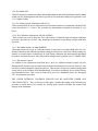
Check that there are Dummy load resistors fitted to the 'SIGNAL I/P' terminals, on all channels
present, see 2.3.6, and switch on the power.
CAUTION : WHEN AC MAINS POWER IS BEING USED, AREAS ON THE LEFT SIDE OF
THE PRINTED CIRCUIT BOARD ARE CONNECTED DIRECTLY TO THE MAINS AND
CARRY VOLTAGES HIGH ENOUGH TO ENDANGER LIFE.
The Digital Displays should now be operating and the left most Red LED on each channel (Inhibit LED)
should be illuminated. After about 30 seconds, provided the 'INHIBIT' switches are in their right hand
position, the 'INHIBIT' LEDs should turn Off. The Displays for all channels should be reading
approximately '000' . If a channel has been configured to read Oxygen levels, then the 'LO' alarm will be
activated otherwise no alarms should be active. This completes the initial checks - switch off the main
power supply to the Instrument.
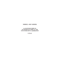
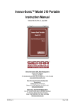
16
Fig 2. Instrument Terminals.
2.2.4 Optional Battery Back-up Unit
If this unit has been supplied with the Instrument then it should be connected up according to the
Instruction manual for the Unit. For convenience, the connection details are included here. The 1300
Instrument should be connected to the AC mains supply as normal and the DC output from the Battery
Back-up Unit connected to the 1300 Instrument terminals which are marked '24V IN' '+ -'.
NOTE : TO AVOID SHORT CIRCUITING THE BATTERY, THE CABLE SHOULD BE
CONNECTED TO THE INSTRUMENT FIRST AND THEN TO THE BATTERY BACK-UP
UNIT TERMINALS.
This is best carried out AFTER the front panel of the 1300 Instrument has been replaced. CAUTION :
DURING INITIAL CONNECTION, A SPARK IS LIABLE TO BE GENERATED AT THE
INSTANT OF CIRCUIT COMPLETION. This is quite normal since the Instrument is not fitted with
an 'ON/OFF'switch. However, this Spark can be avoided if the normal Mains power is present before
the Battery Back-up Unit is connected.
2.2.5 Re-assembling the Instrument
When installation and commissioning procedures have been completed then the front panel of the
Instrument should be re-fitted. Switch off the main power to the Instrument and if fitted, disconnect the
Battery Back-up power, at the terminals of the Battery Back-up Unit. Re-fit the power indicator LED
connector to the Motherboard matching connector. Dress the wires carefully so as to avoid them being
trapped between the Instrument housing and the front panel, and carefully refit the front panel. Use the
switches to ease the Daughterboard protrusions through the holes in the panel and secure the panel with
the four screws. Reconnect the power supply and Battery Back-up, if fitted and finally the lower panel
cover.
2.2.6 Wiring Specification
It is important to realise when considering relative distances between the Instrument and sensors, that
17
the cables used to carry the sensor signals can affect the operation of the system as a whole. All cables
have resistance which causes voltage loss along their length. This resistance decreases as the cross
sectional area of the conductors is increased. ie Basically, the thicker the conductor, the better. (Within
reason). Also, long cable runs act as good aerials and can pick up interference from all sorts of sources,
particularly in Industrial environments. Whilst precautions have been taken in the design of the
Instrument to minimise the effect of interference, it is recommended that where possible, the minimum
requirement of a twin twisted screened pair, having a conductor cross sectional area of 1.5 mm2 is used
for Loop Powered sensors.
2.2.7 Cable for Loop Powered Sensors
If the above recommended cable, ie twin twisted screened pair, having a conductor cross sectional area
of 1.5 mm2, is used for a Loop Powered sensor, then cable runs of up to 1 Kilometre can be used
without an detrimental effects. The screen must be connected to a good mains earth.
2.2.8 Cable for Flammable Sensors
Flammable sensors operate at much higher currents, typically 300 milliamps, so the effect of long cable
runs is much more severe than that on a 4 - 20mA device. The voltage drop along a length of cable can
be calculated by finding the resistance per unit length of the cable and simply applying Ohms Law.
Remember that a 100 metre run of cable actually consists of a loop length of 200 metres. If a cable is
quoted as having a resistance of say 12.5 Ohms per Kilometre, which is about average for a 1.5mm2
cross sectional conductor, then a 100 metre cable run will have a total loop resistance of :
12.5 x 2 = 2.5 Ohms
Using Ohms Law, the voltage drop on a cable of resistance 2.5 Ohms, passing a current of 300
mAmps is :
V = I x R = 0.3 x 2.5 = 0.75 Volt
This means that to obtain 2.00 volts ACROSS THE SENSOR then the Channel card must produce
2.00v + 0.75v = 2.75 Volts ACROSS THE INSTRUMENT TERMINALS.
The Daughterboard Flammable power supply maximum voltage is normally about 3.8 Volts, so , using
a cable having a cross sectional area of 1.5mm2 would permit a maximum cable run of about 250
metres. If the conductors have a cross sectional area of 2.0 mm2, they would have a resistance of about
9.5 Ohms per Kilometre and would permit cable runs of up to 300 metres and if increased to 2.5mm2,
(7.6 Ohms per Kilometre), the permissible length would be increased to about 400 metres. Cables for
the Flammable sensors require THREE conductors, two of which carry the 300mA current. ('A' and
'C') The third conductor carries the sensor output signal voltage.
18
2.3 SENSOR INSTALLATION
2.3.1 General
There are several different sensors available for detection of flammable, toxic and oxygen gases. Ensure
that the correct type of sensor is used with the correctly configured Channel card. Each Channel is
clearly labeled on the front panel with the type of gas it is configured to detect, together with its Unit of
Measurement, and each sensor is also labeled with similar data. Care should be exercised during
installation, not to damage the sensor sinters or membranes or allow them to become contaminated with
grease, water or dirt.
IT IS PARTICULARLY IMPORTANT THAT FLAMMABLE SENSORS ARE NOT EXPOSED
TO SILICON BASED SUBSTANCES OR HALOGENS.
For these reasons, it is strongly recommended that the sensor is kept in its delivered wrapping until the
system and wiring are ready for commissioning.
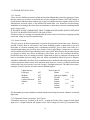
2.3.2 Sensor Location
The type of gas to be detected determines, in general, the physical location of the sensor. Whereas a
gas that is heavier than air will require a low sensor mounting position, a lighter than air gas will
necessitate an elevated mounting point. Consideration should be given to those areas where it is
anticipated that leakage may occur eg. in the vicinity of valves, pipe flanges, compressors etc. and also
to the possibility of pockets of gas collecting in the event of a leak. In this respect, heavier than air gases
eg. propane or butane may tend to accumulate in floor ducts, pits etc. and ventilation should be
provided for these areas as a normal precaution. Lighter than air gases eg. methane or hydrogen will
tend to accumulate between ceiling joists and similar consideration should be given to adequate
ventilation. Additionally, the effects of any ventilation must be considered in the siting of gas sensors and
it may be prudent to mount sensors in air extraction ducts. However, excessive velocities can affect the
sensors and it may be necessary to provide a degree of draught protection. The table below shows
examples of relative densities for some common flammable gases.
Lighter than Air
Hydrogen
Methane
Ammonia
Carbon Monoxide
Ethelene
Air
Heavier than Air
Ethane
1.04
Hydrogen Sulphide
Propane
Butane
1.94
Pentane
Hexane
2.97
Toluene
Heptane
0.07
0.55
0.58
0.97
0.98
1.00
1.20
1.52
2.40
3.14
3.45
The flammable gas sensors should be mounted with the sinter facing downward, whether it is mounted
high or low.
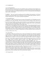
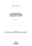
2.3.3 Flammable Sensor Connections (See Fig 4a)
Flammable sensors use Terminals A, B, and C, A being the Positive Drive voltage, B is the Signal
Input and C is Signal common and Negative of the Drive voltage.(See also Fig 2) Sometimes, the
19
Flammable sensor connections are referred to as 'C' (Compensator), 'C/T' (Centre Tap) and 'D'
(Detector). These correspond respectively to 'A' , 'B' and 'C' on the 1300 range of Instruments. If
screened cable is being used, then the screen should be connected to the 'E' terminal.
2.3.4 Flammable Sensor Wiring Variations
There are currently Three different types of Sensor Head available from SAEP Ltd. and the Wiring
colours differ on each sensor. Details of the wiring colours are given below
a. EEV Stainless Steel, VQ4250 Exds Sensor has wiring colours :
BLUE, GREEN/YELLOW, BROWN
Where Blue is the Compensator Lead, which connects to the 'A' Terminal of the 1300.
Green/Yellow is the Signal output Lead which connects to the 'B' Terminal of the 1300.
Brown is the Detector Lead, which connects to the 'C' Terminal of the 1300
Due to possible confusion with european mains wiring colours (Blue, Green/Yellow, Brown) and in the
interests of safety, the manufacturer decided to change the colours of the wiring on all new issues of this
sensor.
The wiring colours on the latest issue of the Stainless Steel VQ4250 sensor are as follows :
RED, YELLOW, BLUE
Where Red is the Compensator Lead, which connects to the 'A' Terminal of the 1300.
Yellow is the Signal output Lead, which connects to the 'B' Terminal of the 1300.
Blue is the Detector Lead, which connects to the 'C' Terminal of the 1300.
b. Groveley 210 Mod FLAM Stainless Steel Exds Sensor has wiring colours :
RED, GREEN, BLUE
Where Red is the Compensator Lead, which connects to the 'A' Terminal of the 1300.
Green is the Signal output Lead, which connects to the 'B' Terminal of the 1300.
Blue is the Detector Lead, which connects to the 'C' Terminal of the 1300.
c. SAEP Ltd. Black Acetal Sensor has the following wiring colours :
RED, GREEN, BLACK
Where Red is the Compensator Lead, which connects to the 'A' Terminal of the 1300.
Green is the Signal output Lead, which connects to the 'B' Terminal of the 1300.
Black is the Detector Lead, which connects to the 'C' Terminal of the 1300.
Sensors a. and b. are normally supplied fitted to an EExe Cast Iron Junction Box and together, form the
ANALOX 2000 Flammable gas sensor unit, suitable for use in Hazardous areas.
Sensor c. , the ANALOX 2001, is a less expensive alternative which can be used in areas which are not
classified as Hazardous.
IT IS VERY IMPORTANT THAT THE FLAMMABLE SENSORS ARE CORRECTLY WIRED
OTHERWISE THE PELLISTORS COULD SUSTAIN PERMANENT DAMAGE.
20
2.3.5 Loop Powered 4-20mA Sensors (See Fig 4b)
Both the Toxic and Oxygen Sensors are of this type and should be connected to Terminals 'A' and
'B'. Terminal A is the Positive '24v' and should be connected to the Sensor/Transmitter positive lead.
Terminal B should be connected to the Sensor Negative. Terminal 'C' is not used. If screened cable is
being used, then the screen should be connected to the 'E' terminal.
2.3.6 Live output 4-20mA Sensors (See Fig 4c)
This type of device, Examples of which are SIMRAD GD100 and other Infra Red sensors, usually
provide a 'Live' 4-20mAmp output and do NOT require application of the Loop power, provided by
the 1300 Daughterboards. In this case, the sensor output should be connected to Terminals 'B' and 'C'.
Terminal B is the Positive Input and Terminal C is Negative Input. If screened cable is being used, then
the screen should be connected to the 'E' terminal.
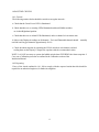
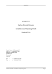
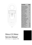
2.3.7 Dummy Loads
Dummy loads are used to simulate a typical sensor, under 'No Gas' conditions thus enabling the
Instrument to be checked out without connecting the sensors. When the Instrument is despatched from
the factory, the appropriate dummy loads are fitted for each Channel card. These should only be
removed when the sensor wiring is ready to be connected and they should be retained as an aid to fault
diagnosis. A dummy load for a Flammable sensor consists of two 3.9 Ohm resistors connected as
shown in Fig 3a. A dummy load for a toxic or oxygen Sensor/Transmitter consists of a single 4700 Ohm
resistor connected as shown in Fig 3b.
Fig.3a Flam. Sensor Dummy load
Fig.3b 4-20mA Sensor Dummy Load
21
Fig 4a. Flammable Sensor Connections.
Fig 4b. Toxic / Oxygen Sensor Connections.
22
Fig 4c. Live Output 4-20mA Sensor Connections.
23
2.4 COMMISSIONING
2.4.1 General Commissioning
Commissioning an ANALOX 1300 system entails checking the Jumper Link Configuration, calibrating
each Channel card in the system using appropriate gases and adjusting the alarm Setpoints. Calibration
gas of known accuracy is required - the calibration procedure is outlined in section 1.6 above.
WARNING : IF THE SYSTEM OPERATES FROM AN AC MAINS SUPPLY, CHECK THAT
THE POWER SUPPLY VOLTAGE INDICATED ON THE AC INPUT TERMINAL COVER
PLATE, MATCHES THE MAINS SUPPLY VOLTAGE. Refer to Fig 2. for position of AC Power
Input Terminals.
2.4.2 Daughterboard Jumper Link Settings
The locations of all Jumper links are shown in Fig 5. The jumper link settings are pre-set, for the
application specified by the customer, before the Channel cards leave the factory. However, these
settings should be checked during the commisioning procedure and verified against the settings below.
To ease the setting procedure, all directions apply to a Channel Daughterboard with the components
toward the user and the Digital Display at the bottom Right corner. The directions are then given as
NORTH, SOUTH, EAST and WEST for the Jumper Link settings. If a Link position is described as
'OFF', then the jumper link should be placed on ONE of the pins only, instead of linking the two pins.
2.4.3 Link Settings for Flammable Sensor
L0 - NORTH :
L1 - OFF
:
L4 - EAST
:
L5 - ON
:
L8 - ON
:
L9 - OFF
:
L2 - SOUTH :
L6 - ON
L10- As Required
L3 - OFF
:
L7 - ON
:
L11- EAST
NOTE : In some installations, if the sensor cable is quite long, it may not be possible to adjust the
'ZERO' control for a Zero reading due to the cable resistance. In this case, try changing the position of
Link L10. However, this Link must always be fitted in either the NORTH or SOUTH positions and not
omitted.
To operate HI and LO Alarms in the NON-LATCHING mode, then Jumper Link L3 should be
placed in the 'ON' position. Apart from L3, the other Jumper Links should remain in the positions as
shown.
2.4.4 Link Settings for Toxic Gas Sensor
L0 - SOUTH :
L1 - ON
:
L4 - EAST
:
L5 - ON
:
L8 - ON
:
L9 - OFF
:
L2 - SOUTH :
L6 - ON
L10- OFF
L3 - OFF
:
L7 - ON
:
L11-EAST
To operate HI and LO Alams in the NON-LATCHING mode, then Jumper Link L3 should be
placed in the 'ON' position. Apart from L3, the other Jumper Links should remain in the positions as
shown.
24
2.4.5 Link Settings for Oxygen Sensor
L0 - SOUTH : L1 - ON
:
L2 - NORTH :
L3 - OFF
L4 - EAST
:
L5 - ON
:
L6 - ON
:
L7 - ON
L8 - ON
:
L9 - OFF
:
L10- OFF
:
L11-EAST
To operate HI and LO Alams in the NON-LATCHING mode, then Jumper Link L3 should be placed
in the 'ON' position. Apart from L3, the other Jumper Links should remain in the positions as shown.
25
26
Fig 5. Daughterboard Jumper Link Locations
27
2.4.6 Initial Setting Up Procedure
Ensure that all sensors are correctly connected to the Instrument. Switch on the system power and
check that the LCD Displays operate. All adjustments should be carried out using the trimming tool
provided or a miniature instrument screwdriver. Any damage to the adjustment controls caused by using
unsatisfactory tools will invalidate the guarantee. Adjustment to the Flammable Sensor drive power can
only be carried out when the front panel has been removed.
2.4.7 Flammable Sensor Drive Power
The control for adjusting the drive power to a Flammable sensor is located on a small Printed circuit
board, which is mounted on top of the Daughterboard at the rear left corner. Locate the terminals 'A' ,
'B' and 'C' IN THE SENSOR JUNCTION BOX. (If the sensors are not of SAEP source, these may
be labelled 'C','C/T'and 'D'). Connect a DVM on a low DC volts range, across the terminations 'A' and
'C', or, in the alternative case, across 'C' and 'D'. See Fig 6. below. Monitor the voltage across the
terminals and adjust the control until the DVM reads 2.00 Volts. Remove the DVM, secure the junction
box lid and repeat the above procedure for all Flammable Channels.
Fig 6. Flammable Sensor Voltage Test
IMPORTANT NOTES:
a.
There are occasions when a different type of Flammable sensor may be used, which operates
with a different terminal voltage. Unless otherwise specified, always assume that the sensor
requires 2.00 Volts.
b.
Unless the cable run between the sensor and the Instrument is very short ie less than about 10
metres, the sensor operating voltage MUST BE MEASURED AT THE SENSOR. Long cable
runs will have significant resistance and will cause a voltage drop along their length. This drop
will be subtracted from the voltage source at the Instrument Terminals and could cause incorrect
operation of the sensor. If the sensor Pellistors are not heated to the correct temperature,
(approx 500 Deg.C), then this will result in a reduction in sensitivity.(See also 2.2.6)
2.4.8 Loop Powered Sensor current
These devices are of the 4-20mA Transmitter type and are supplied from a current limited source on
the Daughterboard. There is no adjustment required for this current since it is controlled directly by the
Sensor/Transmitter. However, the Loop current can be monitored by breaking the current loop circuit at
28
any convenient point, eg in a junction Box, and inserting a milliammeter in series with the circuit.
Alternatively, the sensor Loop current may be measured by connecting a milliammeter to the RED and
BLACK Test points, located on the small Printed circuit board mounted at the rear left corner of the
Daughterboard. Refer to 1.5.5 above for an explanation of the expected current.
2.4.9 Alarm Setpoint Adjustment
When all the Channels have been calibrated the Alarm setpoints should now be checked and adjusted
if necessary. When the Daughterboards leave the factory, the LO and HI alarms are set to 25% and
50% of full scale respectively, for Toxic and Flammable gas, and 19% and 23% for an Oxygen channel.
To adjust these setpoint, proceed as follows.
a.
Operate the 'INHIBIT' switch to its LEFT hand position, thus disabling the alarm circuits.
b.
Push the 'LO/HI' switch to the 'LO' position - the Display will now indicate the LO Alarm
setpoint. Using the trimming tool provided, or a miniature instrument screwdriver, adjust the
'LO' control until the Display indicates the desired setpoint level.
c.
Push the 'LO/HI' switch to the 'HI' position - the Display will now indicate the HI Alarm
setpoint. Using the trimming tool provided, or a miniature instrument screwdriver, adjust the 'H'
control until the Display indicates the desired setpoint level. d. Release the 'LO/HI' switch and
reset the 'INHIBIT' switch to its normal Right hand position. The 'INHIBIT' LED will remain
illuminated for about 30 seconds and then turn off.
29
2.4.10 Motherboard Link Settings
There are three links per channel associated with the alarm relays operation. Each of the relays can be
configured to be either energised, or de-energised when in an alarm condition. When a relay is
configured to de-energise in alarm, this provides a 'Fail-Safe' mode of operaton in that an alarm
condition is the same as a power failure condition. This assumes that the relay contacts are connected to
an external warning system which has an assured power supply. A consequence of configuring the relays
in the 'Fail-Safe' mode, is a considerable increase in the power consumption, since under normal
conditions, ie non alarm state, the relays are energised. This should be bourne in mind if the Instrument
System includes a Battery Back-up unit to maintain operation in the event of the Instrument's normal
power failing. All 1300 range Instruments are delivered with the relays configured in the 'Energise in
Alarm' mode, unless otherwise specified. The links are located on the Motherboard, immediately below
the lower Daughterboard and are shown in Fig.7
Fig 7. Motherboard Jumper Link Locations.
30
2.4.11 Analogue Output 4-20mA
Each Channel is fitted with a 4-20mA Analogue output which represents 0 to 100% of the full scale
value, for that channel. The output is short circuit protected and will operate with loads in the range 50
Ohms to 250 Ohms. Connections are made to Screw Terminals on the Motherboard. These are
marked '4-20mA O/P' '+ -'
2.4.12 Optically Isolated Analogue Output
This facility is supplied as an optional extra and provides a totally galvanically isolated 4-20mA output,
for applications where this is needed. The Instrument should normally be specified, at ordering stage, to
include this facility if required, but it is possible to fit the necessary extra circuits, 'in the field'. For further
details, contact the manufacturer or their agent.
2.4.13 Battery Back-up
An Input is provided on the Motherboard Screw Terminal strip for connection of a 24 Volt
battery/charger unit to enable the Instrument to operate in the event of normal Mains supply failure. This
unit is available as an optional extra device. The length of time for which the Instrument and its sensors
will operate from the battery, depends on several factors :
a.
The Ampere Hour Capacity of the battery.
b.
The Number of Channels in the system.
c.
The Type of Sensors used in the system.
d.
The number of Alarms occurring.
e.
Relay configuration. (See 2.4.10)
It is difficult to give figures for any particular Set-up, but having specified a system, SAEP can give
further advice with regard to Battery Back-up. As a rough guide, a 'Worst-case' system consisting of
the Instrument with 4 flammable sensors and in permanent alarm, using the Standard Battery/charger
unit, would operate for a period of approximately 3/4 hour.
31
APPENDIX A TO ANALOX 1300 Series Manual.
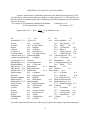
A feature of the Pellistor Combustible gas detectors is the almost universal response to L.E.L.
of hydrocarbons. Almost all detectable gases produce a similar output at L.E.L.. This table lists the
theoretical factors by which the signal with a Calibration gas should be multiplied, to give the equivalent
signal for other gases.
For example : For an Instrument calibrated with Methane
K Methane=112.0
To find equivalent for n-Nonane
K n-Nonane = 35.2
Signal at 50% L.E.L. = 50% x 35.2 = 15.7% (Methane scale)
112.0
Gas
K
Gas
Acetaldehyde 67.3
Acetic Acid
Acetone
57.8
Acetylene
Ammonia
141.7 n-Amyl Alcohol
Benzine
45.6 Biphenyl
n-Butane
65.5 iso Butane
cis-Butene-2
54.2 trans-Butene-2
iso-Butyl Alcohol
59.2 Tert-Butyl Alcohol
n-Butyric Acid 42.5 Carbon Disulphide
Carbon Oxysulphide104.6
Cyanogen
Cyclopropane 69.7 n-Decane
Dimethylamine 64.7 2,3 Dimethylpentane
Dimethylsulphide
48.6 1,4 Dioxane
Ethyl Acetate 57.4 Ethyl Alcohol
81.5
Ethyl Benzine 39.9 Ethylcyclopentane
Ethyleneoxide 57.9 Diethyl Ether
51.8
Ethylmercaptan
62.8 n-Heptane
Hydrazine
50.4 Hydrogencyanide
Hydrogen Sulphide
45.6 Methane
Methyl Alcohol
96.2 Methylamine
Dimethyl Ether 70.0 Methylethylether
Methyl Formate
75.0 Methylmercaptan
Napthalene
38.1 Nitromethane
n-Octane
41.9 n-Pentane
Propane
61.8 n-Propyl Alcohol
Propylene
57.7 Propyleneoxide
Propyne
46.5 Toluene
Trimethylamine
54.3 Vinylethylether
m-Xylene
43.8 p-Xylene
K
60.8
Gas
K
Acetic Anhydride 51.5
63.6 Alkyl Alcohol
57.1
36.6 Aniline
44.1
28.0 1,3 Butadiene
62.5
57.8 Butene-1
50.8
56.7 n-Butyl Alcohol 38.4
83.1 n-Butyl Benzine 35.8
19.8 Carbon Monoxide 84.4
99.9 Cyclohexane
46.0
36.7 Diethelamine
64.7
44.6 2,2 Dimethylpropane44.4
50.0 Ethane
75.8
Ethylamine
58.9
44.4 Ethylene
79.1
Ethyl Formate
49.5
43.2 N-Hexane
41.2
53.4 Hydrogen
85.8
112.0 Metyyl Acetate 55.6
86.5 Methylcyclohexane 49.4
49.3 Methylethylketone 46.2
67.9 Methylpropionate 57.2
64.8 n-Nonane
35.2
51.3 iso-Pentane
51.9
52.7 n-Propylamine 54.1
51.2 iso-Propylether 48.8
45.2 Triethylamine 44.6
46.9 o-Xylene
40.1
43.8
Since these factors are theoretical, they will only give a guide to the response expected in other gases.
32
For exact conversion factors, the Instrument should be calibrated using the relevant gases.
33
APPENDIX B
WARRANTY
Products manufactured by Scottish Anglo Environmental Protection Ltd. (SAEP), are
guaranteed to the original purchaser for a period of One year after purchase by the original user.
Sensors are warranted for Six months. Under this warranty, the liability of SAEP is limited to
servicing,adjusting and replacing any parts that are SAEP manufacture. Final determination of the nature
of and responsibility fro defective or damaged equipment will be made by SAEP personnel. SAEP is
not responsible to the customer for consequential losses or other damages, labour or expense in
connection with or by reason of the use of, or the inability to use the products manufactured by SAEP,
as specified in the equipment manuals. Gas Detection elements, particularly those used in Flammable
sensors, which have been poisoned by contaminant substances are NOT included in this warranty.
Transportation costs of all products returned to SAEP under a warranty claim, must be bourne by the
customer. SAEP cannot be held responsible for repairs or changes made to the equipment, which have
not been authorised by SAEP or damage resulting from abnormal use misuse. SAEP will make available
a warranty service at the customer's location provided the customer elects to pay travelling time and
reasonable expenses. Upon receipt of your SAEP equipment, if damage has been caused, a claim must
be filed promptly with the carrier and SAEP notified. No waiver, alteration or modified form of the
foregoing conditions shall be valid unless made in writing and signed by a director of Scottish Anglo
Environmental Protection Ltd.
Dated : 10th February 1995
34
APPENDIX C
COMBUSTIBLE SENSORS
The elements used in these sensors are of the Catalytic Pellistor type and are sensitive to most
common Combustible gases and vapours. A single sensor may therefore be used to detect a wide range
of these gases. The devices are made from two coils of very fine platinum wire which are embedded in
separate beads of alumina. One device is the detector and the other is a compensating element. The
detecting element is treated with a catalyst which promotes oxidation of the gas and the compensating
element is treated with an oxidation inhibiting agent. The two elements are connected to the Instrument in
a Half Bridge configuration and the excitation current passing through them raises their temperature to
about 500 Deg C. At this temperature, the gas oxidises on the Detector element and raises the
temperature of the bead even further. This alters the resistance of the detector bead and this change in
resistance is measured by the instrument and converted to produce a reading of the gas concentration,
on the LCD display. The output of the device is essentially linear for most gases up to high
concentrations, typically 100% LEL and the response time to 25% LEL is about 2 or 3 seconds. Any
pre-filtering of the gas before it reaches the sensor may lengthen the response time. If the sensors are
required to operate in high gas concentrations for short periods, it has been found that for periods up to
about 2 minutes, 10 second bursts of 8%,10% and 80% methane in air, produce no ill effects.
Prolonged exposure can result in zero drift which may be reversed by operating for a short period in
clean air. Exposure to 40% concentration for longer periods, will begin to destroy the detector surface,
altering the Zero point and reducing the sensitivity. Whenever a sensor is exposed to high concentrations
of Combustible gas, the calibration should be rechecked as soon as possible. The performance of the
sensors may be temporarily impaired by operation in the presence of certain volatile substances
containing halogens or sulphur. The sensors may recover after a short period of operation in clean air.
Whenever the substance produces a permanent effect on the catalyst, resulting in a large reduction in
sensitivity the sensor is said to be Poisoned. Typical substances which can cause poisoning are silicon
oils and grease, anti-knock petrol additives and phosphate esters. Activated carbon filters will provide
adequate protection from poisoning in most cases. Notwithstanding the above comments, the
Combustible gas sensors have an inherently long life. Although the sensors respond to most Combustible
gases, the signals produced vary in magnitude depending on the actual gas to which the sensor is
exposed. The sensors should be calibrated using 50% LEL Methane. NOTE : When the sensors are
used to detect a different gas than that used for calibration, then a correction factor should be applied to
the readings obtained. A table showing conversion factors for various gases is shown in Appendix A .
Acknowledgement : The basic information on Combustible sensors was supplied by English Electric
Valve Co. Ltd.
35
APPENDIX D
OXYGEN SENSORS
The ANALOX 1300 range of Instruments, normally use the CiTiceL* range of oxygen
sensors. These are of the self-powered, diffusion limited, metal-air battery type comprising an anode,
electrolyte and air cathode. At the cathode, oxygen is reduced to hydroxyl ions according to the
equation : O2 + 2H2O + 4e- > 4OH The hydroxyl ions in turn oxidise the metal anode : 2Pb + 4OH >
2PbO + 2H2O + 4e- Overall, the cell reaction may be represented as : 2PbO + O2 > 2PbO The
oxygen cells are current generators. The current is proportional to the rate of consumption of oxygen
and may be simply operated with a low value load resistor connected across the output terminals to
produce a voltage signal. This signal is then passed to an electronic circuit which converts the millivolt
signal to a 4-20 milliamp, loop powered signal. Highly oxidising gases such as ozone and chlorine, will
interfere to the extent of their oxygen equivalent. Sensors should not be subjected to highly corrosive
atmospheres as this will cause premature failure. Most other commonly occurring gases do not affect the
oxygen sensor. Other cross sensitivities : Methane 100% 0 Hydrocarbons 100% 0 Hydrogen 100%
<-2% Carbon Monoxide 20% < -0.5%
* CiTiceL is the registered Trademark of City Technology Ltd.
The information regarding the Oxygen and Toxic gas sensors is reproduced by permission of City
Technology Ltd.
36
APPENDIX E
TOXIC GAS SENSORS.
All Toxic Gas detectors use the CiTiceL range of sensors. They are three electrode, micro fuel
cell units designed to be maintenance free and stable over long periods of time. They use the gaseous
diffusion barrier technology which has proved to be very successful in the Oxygen CiTiceL, and results
in a direct response to volume concentration, rather than to partial pressure. A high reserve of
electrochemical activity ensures that each CiTiceL has a long life and excellent temperature stability. The
three electrode, toxic gas CiTiceL consists of a sensing electrode, a counter electrode and a reference
electrode separated by a thin layer of electrolyte. The central feature of the device is the gaseous
diffusion barrier. This limits the flow of gas to the sensing electrode and ensures that the electrochemical
activity of the electrode is far in excess of the amount of gas with which it has to deal. Gas diffusing to
the sensing electrode reacts at the surface of the electrode either by oxidation (eg CO, H2S, SO2, NO,
H2, HCN HCL), or reduction (NO2 and Cl2). Reactions are catalysed by specially developed
electrode materials and designed to be specific to the gas being sensed. Carbon Monoxide , for
example, reacts at the sensing electrode according to the equation : CO + H2O > CO2 + 2H+ + 2eThe counter electrode acts to balance out the reaction at the sensing electrode by reducing oxygen in air
to water : 1/2 O2 + 2H+ + 2e- > H2O Other CiTiceL sensors react differently on the sensing
electrode, with the gas for which they were designed.
37
ADDITIONAL RELAY ON ANALOX 1300 SERIES INSTRUMENTS
GENERAL DESCRIPTION
In some applications of the ANALOX 1300 Series Instruments, there is a requirement for a set of low
current, volt-free contacts, in addition to those provided by the normal Alarm relays. Typically these
contacts are required to interface with other monitoring devices, computer inputs or building
management systems etc. If the normal relay contacts are connected to external devices such as
beacons or sounders, then it is not normally possible to use the Alarm relays to fulfil this extra function.
The problem is overcome by fitting an extra relay which provides a single set of volt-free change
over contacts, rated at 1 amp 30 volts DC.
The relay is normally in its de-energised state when no alarm conditions exist on ANY OF THE
CHANNELS. If ANY channel enters an alarm state then the additional relay will activate and remain in
this condition until ALL channels return to their normal condition. This assumes that the 'MUTE' button
has been pressed to acknowledge the alarm state and silence the built-in audible warning device.
Note that the additional relay does not change state when the 'MUTE' button is pressed, unless of
course, all measured values have returned to normal, before the 'MUTE' button is pressed. The
preceeding remark applies to units which are configured to provide Latching Alarms. (ie Normal
Factory configuration)
If the ANALOX 1300 is configured to provide NON-Latching alarms, the additional relay will
still operate at the onset of ANY alarm condition but will automatically release after all channels return to
normal.
The additional relay is incorporated on the Motherboard and the connections to the contacts are
made via a 3way screw terminal block, positioned at the Lower Right corner of the Terminal area.
Designation of the terminals is shown in the Diagram below.
IMPORTANT : The Additional relay contacts are only rated 1 Amp 30 Volt DC and are NOT
SUITABLE FOR SWITCHING MAINS VOLTAGE or high current devices.
38
IMPORTANT SAFETY WARNINGS ........................................................................... 1
ANALOX 1300 Series used with SIMRAD Sensor ......................................................... 2
IMPORTANT NOTES .................................................................................................. 3
SECTION 1. OPERATING INSTRUCTIONS. ........................................................................ 4
1.1 INTRODUCTION................................................................................................................ 4
1.1.1 Weight and Dimensions (Overall) ............................................................................ 4
1.2 GENERAL DESCRIPTION ................................................................................................. 5
1.3 CONTROLS AND INDICATORS ...................................................................................... 6
1.3.1 Controls and indicators............................................................................................ 6
1.3.2 The Digital Display.................................................................................................. 6
1.3.3 The HI / LO Switch ............................................................................................... 6
1.3.4 The Power Indicator ............................................................................................... 6
1.3.5 The Alarm Trip LEDs (HI & LO)............................................................................ 6
1.3.6 The Fault LED (FAULT) ........................................................................................ 6
1.3.7 The Over-range LED.............................................................................................. 6
1.3.8 The Inhibit LED ...................................................................................................... 8
1.3.9 The Alarm Setpoint Adjustments (HI & LO)............................................................ 8
1.3.10 The Calibration Adjustments (SPAN & ZERO)..................................................... 8
1.3.11 The Inhibit Switch (ALARM INHIBIT)................................................................. 8
1.3.12 The Internal Controls............................................................................................. 8
1.4 ROUTINE CHECKS............................................................................................................ 9
1.4.1 General................................................................................................................... 9
1.4.2 Reporting................................................................................................................ 9
1.5 CALIBRATION ................................................................................................................. 10
1.5.1 General Information............................................................................................... 10
1.5.2 Flammable Sensor................................................................................................. 10
1.5.3 Toxic Sensor......................................................................................................... 10
1.5.4 Oxygen Sensor ..................................................................................................... 11
1.5.5 Engineering Notes................................................................................................. 11
SECTION 2 INSTALLATION & COMMISSIONING........................................................... 12
2.1 NOTES ON INSTALLATION........................................................................................... 12
2.1.1 Classification of Hazardous Areas.......................................................................... 12
2.1.2 Certification .......................................................................................................... 12
2.1.3 Apparatus Gas Groups.......................................................................................... 12
2.1.4 Temperature Classification..................................................................................... 13
39
2.1.5 Classification Code ............................................................................................... 13
2.1.6 Certifying Authority............................................................................................... 13
2.1.7 Threaded Cable Entries......................................................................................... 13
2.2 INSTALLATION ............................................................................................................... 14
2.2.1 General................................................................................................................. 14
2.2.2 Instrument Installation............................................................................................ 14
2.2.3 Initial Operational Test .......................................................................................... 14
2.2.4 Optional Battery Back-up Unit .............................................................................. 15
2.2.5 Re-assembling the Instrument ................................................................................ 15
2.2.6 Wiring Specification.............................................................................................. 15
2.2.7 Cable for Loop Powered Sensors ......................................................................... 16
2.2.8 Cable for Flammable Sensors................................................................................ 16
2.3 SENSOR INSTALLATION ............................................................................................... 17
2.3.1 General................................................................................................................. 17
2.3.2 Sensor Location.................................................................................................... 17
2.3.3 Flammable Sensor Connections............................................................................. 17
2.3.4 Flammable Sensor Wiring Variations ..................................................................... 18
2.3.5 Loop Powered 4-20mA Sensors........................................................................... 19
2.3.6 Live output 4-20mA Sensors................................................................................. 19
2.3.7 Dummy Loads ...................................................................................................... 19
2.4 COMMISSIONING........................................................................................................... 21
2.4.1 General Commissioning......................................................................................... 21
2.4.2 Daughterboard Jumper Link Settings ..................................................................... 21
2.4.3 Link Settings for Flammable Sensor....................................................................... 21
2.4.4 Link Settings for Toxic Gas Sensor........................................................................ 21
2.4.5 Link Settings for Oxygen Sensor............................................................................ 22
2.4.6 Initial Setting Up Procedure................................................................................... 24
2.4.7 Flammable Sensor Drive Power ............................................................................ 24
2.4.8 Loop Powered Sensor current............................................................................... 24
2.4.9 Alarm Setpoint Adjustment.................................................................................... 25
2.4.10 Motherboard Link Settings .................................................................................. 26
2.4.11 Analogue Output 4-20mA................................................................................... 27
2.4.12 Optically Isolated Analogue Output ..................................................................... 27
2.4.13 Battery Back-up ................................................................................................. 27
APPENDIX A............................................................................................................... 28
APPENDIX B............................................................................................................... 29
APPENDIX C............................................................................................................... 30
APPENDIX D............................................................................................................... 31
APPENDIX E............................................................................................................... 32
ADDITIONAL RELAY ON ANALOX 1300 SERIES INSTRUMENTS................................. 33
40
41
DIAGRAMS
Figure 1 Front Panel Controls and Indicators. . . . . . . . . . . . . . . . . . . . 7
Figure 2 Instrument Screw Terminals . . . . . . . . . . . . . . . . . . . . . . . . 15
Figure 3 Sensor Dummy Loads . . . . . . . . . . . . . . . . . . . . . . . . . . . . 19
Figure 4 Sensor Connections . . . . . . . . . . . . . . . . . . . . . . . . . . . . 20
Figure 5 Daughterboard Jumper Link Locations . . . . . . . . . . . . . . . . . . . 23
Figure 6 Flammable Sensor Voltage Test Diagram. . . . . . . . . . . . . . . . . . . 24
Figure 7 Motherboard Jumper Link Locations. . . . . . . . . . . . . . . . . . . . . 26
Figure 8 Enlarged View of Instrument Terminals. . . . . . . . . . . . . . . . . . . 34
Figure 9 Instrument Enclosure Dimensioned Diagram . . . . . . . . . . . . . . . . . 35
42
==================
ANALOX 1300 SURVEYOR
INSTRUCTION MANUAL
==================
43
44